
Introduction
In industrial automation production lines, the Inovance MD500E series inverter is widely used in fans, pumps, conveyors, mixers, and other loads due to its high reliability, precise vector control, and rich protection functions. However, the ERR04 constant speed overcurrent fault is a frequent “downtime culprit” in field operations—minor cases cause brief production stops, while severe cases damage motor windings or inverter power modules.
This article combines the technical specifications from the official Inovance MD500E manual and field operation cases to systematically dismantle the troubleshooting logic for ERR04 faults, from fault definition and core causes to precise troubleshooting processes and prevention tips. It helps you avoid “blind part replacement” and achieve “quick localization and precise repair.”
1. Official Definition and Trigger Logic of ERR04 Fault
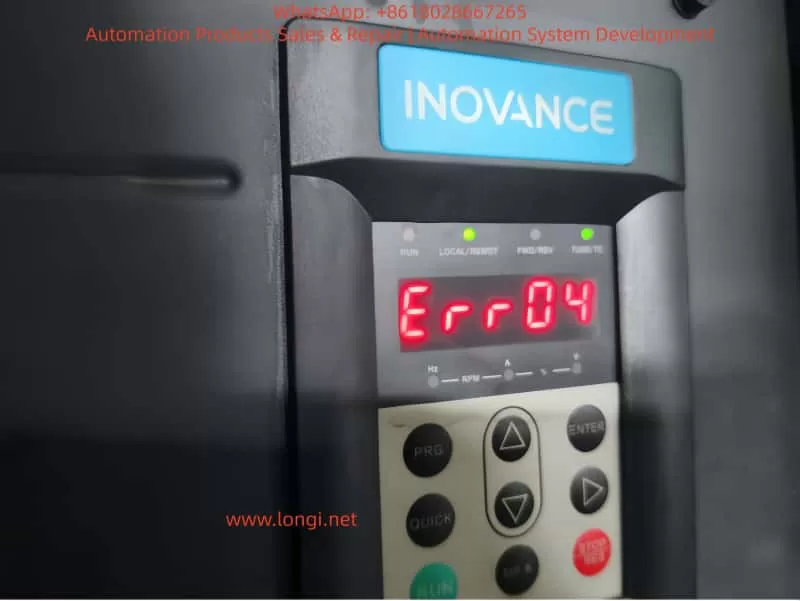
According to the Inovance MD500E Inverter User Manual, the essence of ERR04 fault is “overcurrent during constant speed operation”:
When the motor reaches the set frequency and enters the stable operation stage (i.e., “constant speed stage,” where the frequency no longer changes), the inverter detects via the Hall current sensor that the output current exceeds the overcurrent protection threshold (default threshold is 150% of the inverter’s rated output current or 150% of the motor’s rated current, depending on parameter settings). The inverter immediately triggers protection to stop, and the panel displays “Err04.”
Key Distinction: ERR04 vs ERR03
- ERR03 (Acceleration Overcurrent): Occurs during the acceleration phase (when the frequency rises from 0 to the set value) due to excessive acceleration causing a current surge.
- ERR04 (Constant Speed Overcurrent): Only occurs during the constant speed phase after frequency stabilization, with the core issue being “current exceeding the standard during stable operation.”
This distinction is the starting point for precise troubleshooting—if the fault occurs during acceleration, check “acceleration time”; if during constant speed, focus on “loop, parameters, selection, interference.”
2. 5 Core Causes of ERR04 Fault and Corresponding Solutions
Combining the manual’s technical documentation and over 100 field cases, the root causes of ERR04 faults can be summarized into four categories: output loop abnormalities, control parameter failures, selection mismatches, and interference false reports. Below is a point-by-point dismantling + operational details:
(1) Cause 1: Output Loop Has Grounding or Short Circuit
Fault Mechanism
Insulation damage in the cable, terminal, or motor between the inverter output (U/V/W) and the motor causes phase-to-phase short circuit or ground short circuit, which surges the output current to 3~5 times the rated value, directly triggering ERR04.
High-Frequency Field Scenarios
- Motor junction box water ingress/moisture (e.g., pump rooms, outdoor equipment) leading to reduced insulation of windings to ground.
- Cables mechanically crushed/worn (e.g., conveyor-side cables squeezed by rollers) with damaged insulation.
- Terminal oxidation/looseness (e.g., long-term vibration causing loose terminals) leading to increased contact resistance and local overheating/short circuit.
- Motor winding burnout (e.g., long-term overload causing insulation aging and phase-to-phase short circuit).
Precise Troubleshooting Steps (with Tool Requirements)
- Power-off Safety Operation: Turn off the inverter power and wait for the DC bus capacitor to discharge (measure bus voltage ≤36V with a multimeter or wait 5 minutes).
- Insulation Resistance Test (Core Tool: 500V Megohmmeter):
- Motor side: Open the junction box, disconnect U/V/W wires, and measure winding-to-ground insulation (normal ≥1MΩ, ≥0.5MΩ in humid environments); if <0.5MΩ, the motor is damp/insulation-damaged.
- Cable side: Measure phase-to-phase insulation (U-V, V-W, W-U) and ground insulation (normal ≥1MΩ); if any phase has 0 insulation, the cable is short-circuited.
- Wiring Inspection: Tighten all terminals, clean oxidation with sandpaper, and rewrap with heat shrink tubing.
- Motor Repair: If motor insulation is abnormal, disassemble and dry (bake in a 120°C oven for 4 hours) or replace the motor.
Case: ERR04 Fault in Pump Room
An MD500E-55kW inverter in a factory pump room frequently reported ERR04. Troubleshooting found:
- Water accumulation in the motor junction box, with winding-to-ground insulation only 0.2MΩ.
- Solution: Dry the motor windings + replace the junction box gasket. The fault was completely eliminated.
(2) Cause 2: FVC/SVC Control Without Motor Parameter Identification
Fault Mechanism
The Flux Vector Control (FVC) or Simplified Vector Control (SVC) of MD500E relies on precise motor parameters (stator resistance, inductance, pole pairs, etc.) to achieve “precise torque control.” If parameter identification is not performed, the inverter cannot correctly calculate the motor flux, leading to torque output失控 during constant speed and a current surge.
Key Parameter Description (Manual Original)
| Parameter No. | Parameter Name | Function | Default | Recommended Setting |
|---|---|---|---|---|
| F0-03 | Control Mode Selection | 0=V/F, 1=SVC, 2=FVC | 0 | Select 1/2 for vector control |
| F1-11 | Motor Parameter ID Enable | 0=Not ID, 1=Static, 2=Dynamic | 0 | Must set to 1/2 for vector control |
| F1-00~F1-04 | Motor Nameplate Parameters | Rated Power/Voltage/Current/Frequency/Pole Pairs | —— | 100% accurate input |
Common Field Errors
- Using default parameters (no motor nameplate data input).
- Incorrect nameplate parameter input (e.g., wrong pole pairs leading to vector control failure).
- Control mode set to FVC/SVC but F1-11=0 (no ID).
Solution Steps (with Operational Details)
- Verify Nameplate Parameters: Accurately input the motor’s nameplate data: F1-00 (power), F1-01 (voltage), F1-02 (current), F1-03 (frequency), F1-04 (pole pairs).
- Perform Parameter ID:
- Static ID (F1-11=1): Motor no-load (disconnect load), press “RUN”—the inverter displays “TUNE” and automatically measures stator resistance/inductance (takes ~10 seconds).
- Dynamic ID (F1-11=2): Motor with light load (≤10% rated load), set running frequency to 5~10Hz to measure dynamic parameters (for high-precision applications).
- Verify Effect: Start the motor and check if the panel’s “output current” stabilizes within ±10% of the rated current (e.g., for a 100A rated motor, constant speed current should be 90~110A).
Case: ERR04 Fault in Conveyor
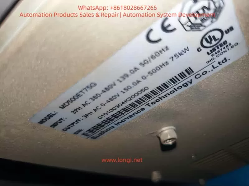
An MD500E-75kW inverter (FVC control) for a conveyor reported ERR04 during constant speed with a current of 180A (motor rated 120A) because no parameter ID was done. Solution:
- Input motor nameplate parameters (F1-00=75kW, F1-01=380V, F1-02=140A, F1-03=50Hz, F1-04=4).
- Set F1-11=1 and perform static ID.
- After restart, constant speed current stabilized at 130A, and the fault disappeared.
(3) Cause 3: Inappropriate Overcurrent Stall Suppression Settings
Fault Mechanism
Overcurrent Stall Suppression is the inverter’s “anti-trip buffer mechanism”—when constant speed current exceeds the set value, the inverter automatically reduces frequency to decrease motor torque and limit current. Inappropriate parameter settings lead to:
- Not enabled: Current exceeds the threshold and trips directly.
- Action current too high: Fails to suppress overcurrent in time.
- Suppression gain too low: Insufficient frequency reduction, so current still exceeds the standard.
Key Parameter Description (Manual Original)
| Parameter No. | Parameter Name | Default | Range | Recommended Value |
|---|---|---|---|---|
| F3-19 | Overcurrent Stall Suppression Enable | 0 | 0~1 | 1 (Must Enable) |
| F3-18 | Overcurrent Stall Action Current | 150% | 50%~200% | 120%~150% of motor rated current |
| F3-20 | Overcurrent Stall Suppression Gain | 30 | 0~100 | 20~40 |
- F3-19=1: Enable buffer protection.
- F3-18: Current threshold for triggering frequency reduction (based on motor rated current).
- F3-20: Sensitivity of frequency reduction (higher value = faster reduction).
Common Field Errors
- F3-19=0 (buffer disabled, no protection).
- F3-18 set to 200% (action too late, current already exceeds threshold).
- F3-20 set to 10 (too slow to suppress overcurrent).
Solution Steps (with Adjustment Logic)
- Enable Function: Set F3-19 to 1.
- Adjust Action Current: If constant speed current often approaches 150% of the rated value, set F3-18 to 120%~130% (trigger frequency reduction early).
- Optimize Suppression Gain: If current still doesn’t drop after frequency reduction, set F3-20 to 30~40 (speed up frequency reduction).
- Verify Effect: Simulate load fluctuations (e.g., increase conveyor load) and check if the inverter automatically reduces frequency and current falls back to a safe range.
Case: ERR04 Fault in Fan
An MD500E-110kW inverter for a fan reported ERR04 with F3-19=0 and F3-18=180%—constant speed current reached 200A (motor rated 160A). Solution:
- Set F3-19=1, F3-18=130%, F3-20=35.
- After startup, load increase caused current to reach 190A (130%×160A=208A)—the inverter automatically reduced frequency to 45Hz, and current fell back to 170A, avoiding tripping.
(4) Cause 4: Inverter Selection Is Too Small
Fault Mechanism
The inverter’s rated output current must be ≥ the motor’s rated current (for constant torque loads like conveyors/mixers) or ≥ the motor’s maximum running current (for square torque loads like fans/pumps). If the selection is too small, even if the motor is not overloaded, the constant speed running current will exceed the inverter’s rated output current, triggering ERR04.
Selection Principle (Manual Mandatory Requirement)
- Constant torque loads (conveyors, mixers): Inverter rated current ≥ motor rated current ×1.1.
- Square torque loads (fans, pumps): Inverter rated current ≥ motor rated current ×1.0 (consider starting current).
- Frequent start/stop loads: Inverter rated current ≥ motor rated current ×1.2.
Common Field Errors
- Using a 75kW inverter for a 100kW motor (motor rated current 180A, inverter rated 150A).
- Selecting by “power matching” instead of “current matching” (e.g., a 100kW fan’s rated current may be lower than a 100kW conveyor’s, but starting current is higher).
Solution Steps
- Check Current Parameters: Compare the motor’s nameplate “rated current” with the inverter’s nameplate “rated output current.”
- Calculate Load Current: For fans/pumps, calculate the maximum running current (e.g., fan full-load current).
- Replace Inverter: Select an inverter with a rated output current ≥ motor rated current ×1.1 (e.g., for a 180A motor, choose 200A or higher).
Case: Mixer ERR04 Selection Rectification
An MD500E-75kW inverter (rated current 150A) for a 100kW mixer (rated current 180A) reported ERR04 because constant speed current reached 160A (exceeding the inverter’s rating). Solution:
- Replace with an MD500E-110kW inverter (rated current 210A).
- After resetting parameters, startup current stabilized at 170A, and the fault was eliminated.
(5) Cause 5: External Interference Causing False Report
Fault Mechanism
External electromagnetic interference (e.g., welders, high-frequency heaters, PLCs) couples into the inverter’s current detection circuit, causing the Hall sensor to falsely report “overcurrent.” Alternatively, damaged drive boards or Hall devices lead to abnormal current detection values.
Field Troubleshooting Steps (with Judgment Logic)
- Check Historical Fault Records: Use the MD500E’s historical fault query (F9-00~F9-07) to view the actual current value at the time of fault:
- If the fault current does not reach the F3-18 setting (e.g., F3-18=150% but fault current is only 120%), it’s interference false report.
- If the current reaches or exceeds the setting, it’s real overcurrent.
- Investigate External Interference Sources:
- Check cable shielding: The output cable’s shielding layer must be single-ended grounded (ground at the inverter side, not the motor side, to avoid loop current).
- Keep away from interference sources: Welders/high-frequency heaters should be ≥1 meter from the inverter.
- Add anti-interference devices: Install AC reactors on the input side (suppress power harmonics) and output reactors on the output side (suppress cable radiation interference).
- Detect Hardware Damage: If interference is ruled out but ERR04 persists, test the Hall sensor (normal output: 0~5V/0~10V, proportional to current); if output is abnormal (e.g., always 5V), the sensor is damaged—replace the drive board (MD500E’s drive board integrates the Hall device).
Case: Interference-Induced ERR04 False Report
An MD500E-55kW inverter in a workshop reported ERR04 only when a nearby welder was working. Historical records showed the fault current was only 110A (F3-18=150%). Solution:
- Install an input AC reactor (ACL-55A) on the input side.
- Single-ended ground the output cable shielding layer.
- The fault disappeared, and no false reports occurred when the welder was working.
3. Standardized Troubleshooting Process for ERR04 Fault
To avoid blind operations, summarize the “5-Step Precise Troubleshooting Method” (with tool/parameter lists):
| Step | Operation Content | Key Tools/Parameters |
|---|---|---|
| 1 | Check historical records: Read F9-00~F9-07 to confirm current, frequency, and load status at fault | Inverter panel/MD500E debugging software |
| 2 | Check output loop: Power off to test motor/cable insulation and wiring terminals | 500V Megohmmeter, multimeter |
| 3 | Check control parameters: Verify F0-03 (control mode), F1-11 (parameter ID), F3-18~F3-20 (overcurrent stall) | Manual parameter table, motor nameplate |
| 4 | Check selection match: Compare motor rated current with inverter rated output current | Motor/inverter nameplates |
| 5 | Check external interference: Test historical current values, check shielding grounding, and add anti-interference devices | Oscilloscope, AC/output reactors |
4. O&M Tips to Prevent ERR04 Fault
- Regular Parameter Backup: Back up parameters quarterly using the inverter’s “parameter backup function” (F9-10=1) to avoid irrecoverable loss after misoperation.
- Parameter ID Cycle: Perform static parameter ID (F1-11=1) every 2 years or after motor replacement.
- Cable Maintenance: Inspect output cable insulation every 6 months to avoid mechanical damage.
- Interference Protection: Install inverters away from interference sources; use shielded cables for input/output, with single-ended grounding.
- Load Monitoring: Monitor real-time current via the inverter’s “real-time current display” (panel or monitoring software)—if constant speed current is close to 150% of the rated value long-term, adjust parameters or selection in time.
5. Summary
ERR04 constant speed overcurrent fault is a “high-frequency pain point” for Inovance MD500E, but strict adherence to the “definition→cause→troubleshooting→solution” logic, combined with the manual’s specific parameters and field operational details, enables quick problem localization. The key is to reject empiricism:
- Don’t blindly replace the inverter—check parameter ID first.
- Don’t ignore historical records—check if the fault current is truly excessive.
- Don’t adjust parameters by feel—strictly follow the manual’s recommended ranges.
For field O&M personnel, mastering the parameter meanings of MD500E (e.g., F1-11, F3-18), selection principles (current matching over power matching), and interference troubleshooting methods (historical records + shielding grounding) is the core capability to solve ERR04 faults. I hope this “precise troubleshooting guide” becomes a “toolbook” for your field operations, helping you quickly resume production and reduce downtime losses.
Appendix: MD500E ERR04 Fault Core Parameter Quick Reference Table
| Parameter No. | Parameter Name | Function | Recommended Setting |
|---|---|---|---|
| F0-03 | Control Mode Selection | 0=V/F, 1=SVC, 2=FVC | Select 1/2 for vector control |
| F1-00~F1-04 | Motor Nameplate Parameters | Rated Power/Voltage/Current/Frequency/Pole Pairs | 100% accurate input |
| F1-11 | Motor Parameter ID Enable | 0=Not ID, 1=Static, 2=Dynamic | Must set to 1/2 for vector control |
| F3-19 | Overcurrent Stall Suppression Enable | 0=Disable, 1=Enable | Must set to 1 |
| F3-18 | Overcurrent Stall Action Current | Overcurrent trigger for frequency reduction | 120%~150% of motor rated current |
| F3-20 | Overcurrent Stall Suppression Gain | Frequency reduction sensitivity | 20~40 |