
Introduction
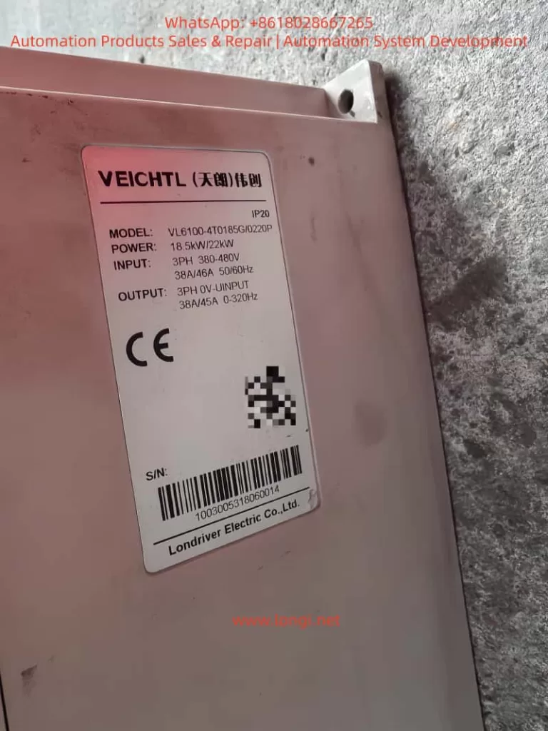
The Tianlang Weichuang VL6100-SM series frequency inverter is a high-performance, multi-functional vector-type general-purpose inverter widely used in industries such as machine tools, packaging, textiles, ceramics, mining, food, chemicals, and more. This article will provide a detailed introduction to the operation panel functions, password setting and elimination, parameter access restrictions, parameter restoration to factory settings, as well as how to implement external terminal forward/reverse control and external potentiometer frequency adjustment. Additionally, it will analyze common fault codes and their solutions.
I. Operation Panel Function Introduction
1.1 Composition of the Operation Panel
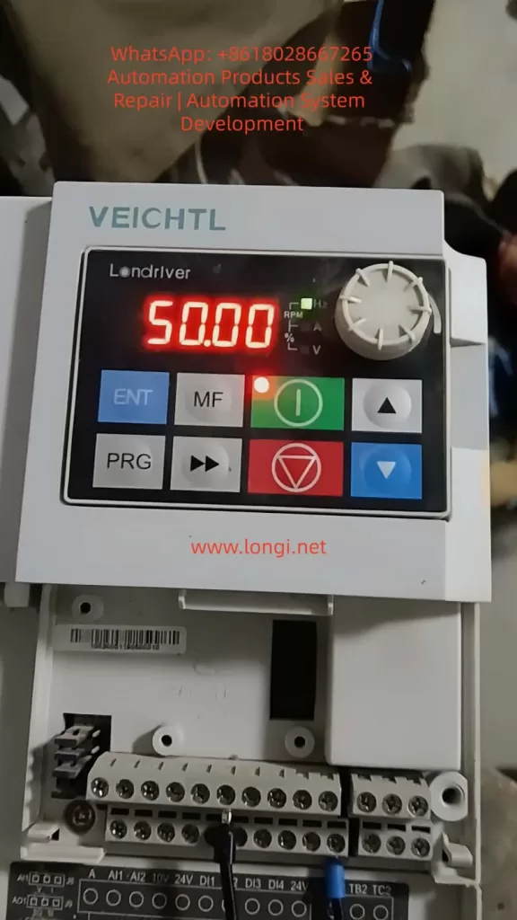
The operation panel (EKPG101 keyboard) of the VL6100-SM series frequency inverter mainly consists of the following parts:
- 5-digit 8-segment LED Display: Used to display output frequency, current, parameter settings, and abnormal information.
- 4 Indicator Lights: Indicate running status, frequency display, current display, and voltage display, respectively.
- 8 Buttons: Include run, stop/reset, up, down, multifunction, shift, program, and confirm buttons.
- 1 Rotary Potentiometer: Used to change numerical settings; rotating clockwise increases the value, while rotating counterclockwise decreases it.
1.2 Password Setting and Elimination
Password Setting
To protect the inverter parameters from unauthorized modifications, a user password can be set. The specific steps are as follows:
- Enter Parameter Setting Mode: Press the “program button” to enter the primary menu. Use the “up” or “down” buttons to select “P07 Group” (keyboard display and function code management) and press the “confirm button” to enter the secondary menu.
- Set Password Parameter: In the secondary menu, select “P07.11” (user password) and press the “confirm button” to enter the parameter setting interface.
- Input Password: Use the “up,” “down,” and “shift” buttons to input a 6-digit numerical password. Press the “confirm button” to save the settings.
Password Elimination
To eliminate the set password, re-enter the “P07.11” parameter setting interface and set the password value to “000000.” Press the “confirm button” to save the changes.
1.3 Parameter Access Restrictions
To prevent unauthorized personnel from modifying critical parameters, parameter access restrictions can be set. The specific steps are as follows:
- Enter Parameter Setting Mode: Same as Step 1 in the password setting section.
- Set Access Restriction Parameter: In the secondary menu, select “P07.07” (function code modification attribute) and press the “confirm button” to enter the parameter setting interface.
- Select Restriction Level: Use the “up” or “down” buttons to select the restriction level. “0” indicates modifiable, while “1” indicates non-modifiable. Select “1” and press the “confirm button” to save the settings.
1.4 Restoring Parameters to Factory Settings
To restore the inverter parameters to their factory settings, follow these steps:
- Enter Parameter Setting Mode: Same as Step 1 in the password setting section.
- Select Restore Factory Parameters: In the secondary menu, select “P00.26” (restore factory parameter settings) and press the “confirm button” to enter the parameter setting interface.
- Execute Restoration: Use the “up” or “down” buttons to select the restoration scope. “1” indicates restoring factory parameters excluding motor parameters, while “2” indicates restoring factory parameters including motor parameters. Select the desired option and press the “confirm button” to execute the restoration.
II. External Terminal Forward/Reverse Control and External Potentiometer Frequency Adjustment
2.1 External Terminal Forward/Reverse Control
Wiring Method
- Forward Control: Connect one end of an external forward start button to the “DI1” terminal of the inverter and the other end to the common terminal (COM).
- Reverse Control: Connect one end of an external reverse start button to the “DI2” terminal of the inverter and the other end to the common terminal (COM).
Parameter Settings
- Set DI1 as Forward Command Source: Enter “P05.00” (DI1 terminal function selection) and set it to “1” (forward run FWD or run command).
- Set DI2 as Reverse Command Source: Enter “P05.01” (DI2 terminal function selection) and set it to “2” (reverse run REV or forward/reverse running direction).
- Set Command Source: Enter “P00.01” (command source selection) and set it to “1” (terminal command channel).
2.2 External Potentiometer Frequency Adjustment
Wiring Method
Connect the two ends of an external potentiometer to the “+10V” power supply terminal and the “GND” ground terminal of the inverter, respectively. Connect the middle tap to the “AI1” analog input terminal.
Parameter Settings
- Set AI1 as Voltage Input: Locate the “J8” jumper setting (refer to the physical unit for the exact location) and set AI1 to voltage input (0-10V).
- Set Frequency Source: Enter “P00.02” (primary frequency source selection) and set it to “0” (digital setting, but will be adjusted via AI1 later).
- Set AI1 Input Range: Enter “P20.00” (AI1 input lower limit) and “P20.01” (AI1 input upper limit) and set them to “0.00V” and “10.00V,” respectively.
- Set Frequency Range: Enter “P00.10” (maximum frequency) and “P00.08” (preset frequency) and set them according to actual requirements.
III. Fault Codes and Solutions
3.1 Common Fault Codes and Causes
| Fault Code | Fault Type | Possible Causes |
|---|---|---|
| Err01 | Brake VCE Fault | Brake tube damage, brake resistor damage, brake resistor short circuit |
| Err02 | Acceleration Overcurrent | Inverter output circuit grounded or short-circuited, vector control without parameter tuning, acceleration time too short |
| Err03 | Deceleration Overcurrent | Same as acceleration overcurrent, deceleration time too short |
| Err04 | Constant Speed Overcurrent | Inverter output circuit grounded or short-circuited, vector control without parameter tuning |
| Err05 | Acceleration Overvoltage | Input voltage too high, external force dragging motor during acceleration |
| Err06 | Deceleration Overvoltage | Input voltage too high, external force dragging motor during deceleration |
| Err07 | Constant Speed Overvoltage | Input voltage too high, external force dragging motor during operation |
| Err08 | 24V Short Circuit | 24V terminal shorted to ground, excessive load on 24V power supply |
| Err09 | Undervoltage | Instantaneous power failure, inverter input voltage too low, bus voltage too low |
| Err10 | Inverter Overload | Excessive load or motor stall, undersized inverter selection |
| Err11 | Motor Overload | Inappropriate motor protection parameter settings, excessive load or motor stall |
3.2 Solutions
Brake VCE Fault (Err01)
- Check Brake Tube: Confirm if the brake tube is damaged and replace it if necessary.
- Check Brake Resistor: Confirm if the brake resistor is damaged or short-circuited and replace it if necessary.
- Check Wiring: Confirm the brake resistor wiring is correct and free of short circuits.
Acceleration/Deceleration/Constant Speed Overcurrent (Err02/Err03/Err04)
- Check Peripheral Faults: Confirm if the inverter output circuit is grounded or short-circuited.
- Parameter Tuning: Perform motor parameter tuning to ensure accurate parameters for vector control.
- Adjust Acceleration/Deceleration Time: Increase the acceleration/deceleration time according to the load conditions.
- Adjust Voltage: Adjust the input voltage to the normal range.
Acceleration/Deceleration/Constant Speed Overvoltage (Err05/Err06/Err07)
- Adjust Voltage: Adjust the input voltage to the normal range.
- Cancel External Force Dragging: Check and cancel any external force dragging the motor during acceleration/deceleration.
- Install Brake Resistor: Consider installing a brake resistor to dissipate excess energy during deceleration if not already installed.
24V Short Circuit (Err08)
- Check Wiring: Confirm if the 24V terminal is shorted to ground and check the wiring connections.
- Reduce Load: If the 24V power supply load is too high, reduce the load or replace it with a higher-capacity 24V power supply.
Undervoltage (Err09)
- Reset Fault: Attempt to reset the fault and restart the inverter.
- Adjust Voltage: Adjust the input voltage to the normal range.
- Seek Technical Support: If the issue persists, seek technical support from the manufacturer or agent.
Inverter/Motor Overload (Err10/Err11)
- Reduce Load: Confirm if the load is excessive or if the motor is stalled, reduce the load, and check the motor and mechanical conditions.
- Adjust Protection Parameters: Set the motor protection parameters correctly according to the motor nameplate parameters.
- Replace Inverter: If the inverter is undersized, select a higher-power inverter.
Conclusion
The Tianlang Weichuang VL6100-SM series frequency inverter is widely used in various industrial fields due to its high performance and versatility. This article provides a detailed introduction to the operation panel functions, password setting and elimination, parameter access restrictions, parameter restoration to factory settings, as well as external terminal forward/reverse control and external potentiometer frequency adjustment methods. Additionally, it analyzes common fault codes and their solutions. It is hoped that this article will serve as a useful reference for users in operating and maintaining the VL6100-SM series frequency inverter.