
Introduction
The INVT Goodrive35 (GD35) series inverter is a high-performance closed-loop vector control inverter widely used in industrial automation fields such as fans, water pumps, elevators, and precision machinery. The product adopts advanced sensorless vector control technology and a DSP control system, supporting the drive of asynchronous motors and permanent magnet synchronous motors to achieve the integration of torque control and speed control. The GD35 inverter boasts excellent control precision, with a speed control accuracy of up to ±0.02% (under PG vector control mode) and a torque response time of less than 10ms (with PG mode). It also supports various encoder signal processing to meet complex high-precision transmission requirements. Additionally, it features a modular design that can be customized via expansion boards for applications such as PROFIBUS, CANopen, and Ethernet communication.
In actual operation, the dEu fault (speed deviation fault) is one of the common protection mechanisms in the GD35 series. The fault code is 34, typically triggered in closed-loop vector control mode (P00.00=3). When the deviation between the actual motor speed and the set speed exceeds a set threshold and persists for a certain period, the inverter shuts down for protection to prevent equipment damage or system loss of control. According to the INVT official manual, the trigger for a dEu fault stems from abnormal loads or mismatched control parameters, but it can be effectively resolved through systematic diagnosis and parameter optimization. This article provides an in-depth analysis from the perspectives of principles, causes, diagnosis, solutions, case studies, and prevention, aiming to provide practical guidance for engineers and technicians.
Principles of Closed-Loop Vector Control in GD35 Inverters
Closed-loop vector control is the core technology of the GD35. It achieves precise speed and torque regulation by providing real-time feedback on motor speed and current. The fundamental idea of vector control is to decompose the stator current vector of an asynchronous or synchronous motor into an excitation current component (generating the magnetic field) and a torque current component (generating torque), thereby simulating the control characteristics of a DC motor. Specifically, the GD35 uses coordinate transformations (Clark and Park transforms) to convert three-phase currents into DC quantities in the d-q axis coordinate system for easy PI regulator control.
In closed-loop mode, speed feedback usually comes from an encoder (PG card) or a sensorless estimation algorithm. The set speed (from the keypad, analog inputs AI1/AI2/AI3, pulse HDI, or communication) is compared with the actual feedback speed to form a speed deviation signal. This signal is input into the speed loop PI regulator (P03 group parameters), which outputs a torque set value. This is then regulated by the current loop PI (P03.09 and P03.10) to ultimately generate PWM signals that drive the IGBT module to output variable frequency voltage.
Speed deviation detection is the key to the protection mechanism. The GD35 defines the threshold through P11.14 (Speed Deviation Detection Value, range 0.0~50.0%, default 10.0%) and P11.15 (Detection Time, range 0.0~10.0s, default 1.0s). When |Actual Speed – Set Speed| / Max Speed > P11.14 and the duration > P11.15, a dEu fault is triggered. If P11.15 is set to 0.0s, this protection is disabled. The detection logic is illustrated as follows: the deviation curve continues to run when t1 < t2 (where t2 = P11.15); otherwise, a fault shutdown occurs. This mechanism ensures the system responds promptly to sudden load changes or parameter mismatches, avoiding motor overload or stalling.
Furthermore, the GD35 supports flux-weakening control (P03.26~P03.28) to adjust the magnetic flux automatically at high speeds to extend the speed range. Torque control mode (P03.11) can be implemented through various set methods (such as keypad P03.12 or communication), with the torque limit set by P03.18~P03.21. These functions are closely related to speed deviation; improper parameters may amplify the deviation and cause faults.
Definition and Trigger Conditions of dEu Fault
The full name of the dEu fault is “Speed Deviation Fault.” It is a dedicated protection for the GD35 under closed-loop vector control, and the fault code is stored in the history records P07.27~P07.32. The trigger condition is based on the deviation calculation of the speed closed loop: Deviation Percentage = |(Feedback Speed – Set Speed)| / Max Output Frequency (P00.03) × 100%. When the deviation exceeds the threshold set by P11.14 and persists for longer than P11.15, the inverter outputs a fault signal, the keypad displays “dEu,” and the output terminal action is determined by the P11.13 setting (whether to act during undervoltage or reset).
Mathematically, the dynamic response of the speed loop can be described as: speed error e(t) = r(t) – y(t), where r(t) is the set speed and y(t) is the feedback speed. The PI regulator output is u(t) = Kp * e(t) + Ki ∫ e(t) dt, where Kp is the proportional gain (P03.00/P03.03) and Ki is the inverse of the integral time (1/P03.01/P03.04). If the system damping is insufficient or the load disturbance is large, e(t) will amplify, causing the deviation to exceed the limit.
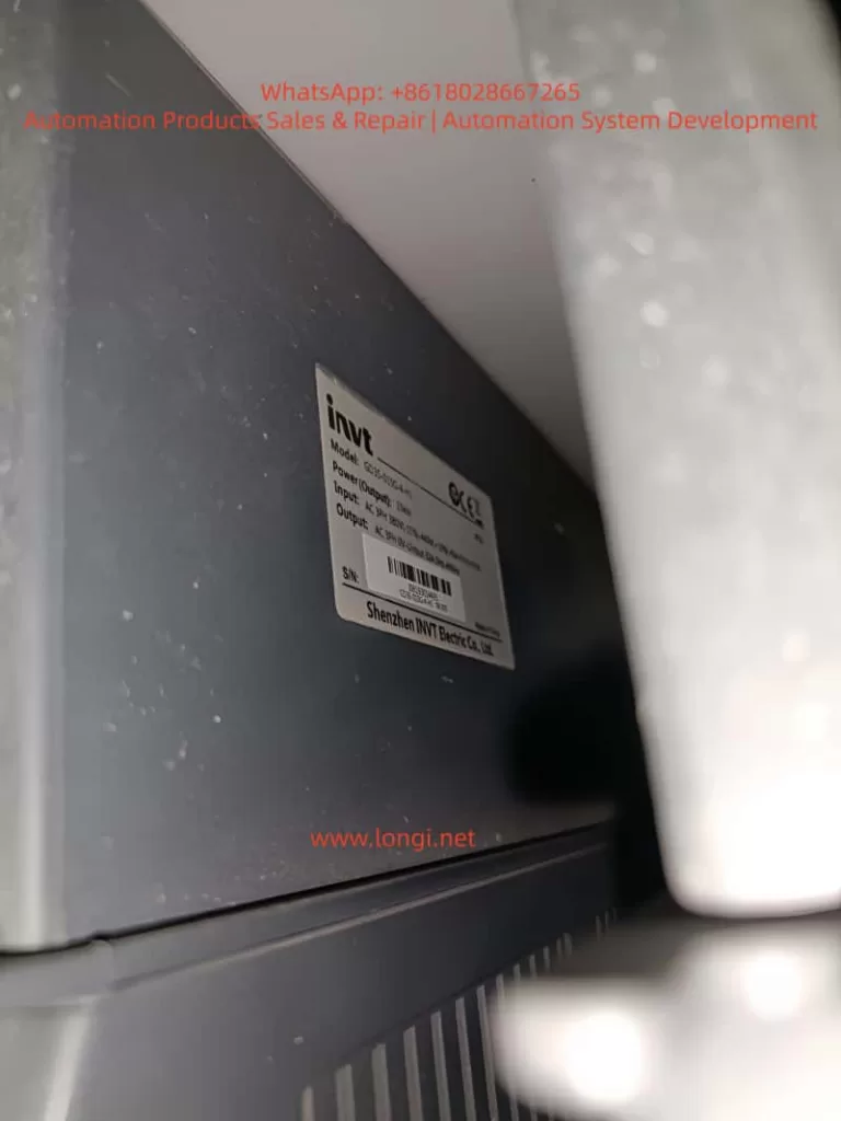
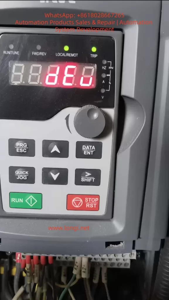
The photo provided by the user shows an inverter model GD35-015G-4 (15kW, 380V), with a display of 8.080 Hz (likely the set frequency), and a deviation detection diagram marked with P11.15 as 1.0s. The diagram illustrates that if the deviation fluctuates between 0.1s and 1.0s, no fault occurs if t1 < 1.0s; a fault is triggered at t2 = 1.0s. In practical applications, deviation detection is only effective during operation and is related to the control mode (P11.16 affects 0Hz output in open-loop vector or VF mode, but dEu is mainly for closed-loop).
Fault Cause Analysis
The root cause of the dEu fault lies in the inability of the speed closed loop to maintain stability. Specific causes can be divided into three categories: mechanical, electrical, and parameter-related.
- Mechanical Load Issues: Excessive load or stall is the most common cause. For example, bearing seizure, loose drive belts, or material blockage prevent the motor from keeping up with the set speed. The GD35 manual explicitly identifies “excessive load or stall” as the primary factor. In this case, the actual speed y(t) lags behind r(t), and the accumulated deviation exceeds the threshold. Quantitatively, if the load torque exceeds 150% of the motor’s rated torque (overload capacity), the fault may be triggered within one minute.
- Mismatched Control Parameters: Improper speed loop PI parameters (P03.00~P03.05) can lead to sluggish response or oscillation. The switching frequencies P03.02/P03.05 default to 5.00Hz/10.00Hz. If the low-frequency gain is too small (<20.0) or the high-frequency gain is too large (>30.0), the deviation can easily exceed 10%. The current loop PI (P03.09/P03.10, default 1000) affects torque output; if not optimized, unstable magnetic flux in the flux-weakening region (P03.26=1200, P03.27=1200) can also amplify deviation. An excessively long torque set filtering time P03.13 (default 0.100s) delays response.
- Encoder or Feedback Issues: In PG mode, encoder wire breakage (ENC1O, code 37), reverse connection (ENC1D, code 38), or Z-pulse faults (ENC1Z, code 39) cause feedback distortion. In sensorless mode, which relies on estimation algorithms, if motor parameters (P02 group: rated power P02.01, frequency P02.02, speed P02.06) are inaccurate from auto-tuning (P00.15=1 for rotating or 2 for stationary), speed estimation errors increase.
- Electrical Interference and Hardware Faults: Grid fluctuations cause unstable DC bus voltage (UV fault code 10 may be interlocked), or abnormal current detection circuits (ItE code 19). External interference (such as electromagnetic noise) affects analog input AI or communication set values. If the torque limit settings (P03.18~P03.21, default 180.0%) are too low, they can also restrict speed tracking.
- Application-Specific Factors: In multi-motor synchronization or positioning control (P21/P22 groups), incorrect indexing commands or inappropriate positioning gains P21.02/P21.03 can induce deviation. Insufficient pre-excitation time P03.25 (default 0.000s) results in slow magnetic field establishment at startup, causing initial deviation.
These causes often interact; for example, sudden load changes can amplify parameter defects. By checking P07.33~P07.48, one can view the operating frequency, voltage, and current data at the time of the fault to trace the root cause.
Diagnostic Methods
Diagnosing a dEu fault requires a systematic approach to ensure safety (reset before powering off).
- Preliminary Check: When “dEu” is displayed on the keypad, press STOP/RST to reset. Check P07.27 for the current fault type (34 indicates dEu) and analyze the recurrence frequency in the history records P07.28~P07.32. Monitor the deviation by comparing P07.33 (Operating Frequency) with P07.34 (Ramp Set Value).
- Parameter Reading: Enter the P11 group to confirm that the defaults for P11.14/P11.15 have not been altered. Check the P03 group to see if the speed loop PI matches the machine defaults (for asynchronous motors, P03.00=16.0, P03.01=0.200s). Verify the P02 group motor parameters match the nameplate.
- Hardware Inspection: Check motor wiring and encoder connections (ensure no ENC1O or related faults). Use a multimeter to measure input voltage stability and rule out short circuits (ETH1/ETH2 codes 32/33). Perform a no-load run test; if no fault occurs, the issue is on the load side.
- Dynamic Monitoring: During operation, check P17.00 (Output Frequency), P17.01 (Output Current), and P17.15 (Torque Set Value). Use an oscilloscope to capture the speed waveform and quantify the deviation timing.
- Advanced Tools: Connect a host computer via MODBUS (P14 group) or Ethernet (E-NET code 30) to read real-time data. INVT debugging software can simulate operation and analyze PI response curves.
After diagnosis, if the deviation is brief (<1.0s), it can be considered a false alarm; persistent deviation requires optimization.
Solutions
Resolving dEu faults follows a “Check-Adjust-Verify” process.
- Load Optimization: Confirm there is no mechanical jamming and that the load does not exceed the inverter’s rating (150% for 1 min, 180% for 10s). If stalled, clean the transmission system. If the load is too heavy, use staged starting or adjust acceleration/deceleration times (P00.11~P00.12).
- Detection Parameter Adjustment: Increase P11.15 to 2.0~5.0s to avoid triggering on transient deviations. If the application allows, increase P11.14 to 15.0~20.0%. However, do not overdo this to prevent protection failure.
- Control Parameter Tuning: Start from no-load and gradually increase the P03.00/P03.03 gain (from low to high to avoid oscillation). Shorten the P03.01/P03.04 integral time (0.100~0.500s) to improve response. If the current loop oscillates, reduce P03.09/P03.10 to 800~1200. Adjust P03.26/P03.27 in the flux-weakening region to ensure high-speed stability.
- Motor Auto-Tuning: Set P00.15=1 (rotating auto-tuning) or 2 (stationary) to reset P02 parameters. For synchronous motors, check the magnetic pole position (P20.02 direction).
- Hardware Repair: Replace encoder cables and shield against interference. If current is abnormal, replace Hall sensors or the main control board.
- Torque Integration: If in torque mode (P03.11≠0), adjust the set filtering P03.13. Set the upper limits P03.20/P03.21 to 200.0% for margin.
Verification: Observe P07 for new faults during light-load operation, then gradually increase the load for testing. Restart the inverter (cut power for 5 minutes) if necessary.
Case Studies
Case 1: Load Stall in Fan Application
A GD35-015G-4 driving a fan in a chemical plant experienced frequent dEu faults. Diagnosis showed P07.33=50.00Hz with a 15% deviation. Cause: Air duct dust accumulation causing a stall. Solution: Clean the air duct, increase P11.15 to 3.0s, and optimize P03.00 to 25.0. Result: Stable operation with deviation <5%.
Case 2: Parameter Mismatch in Pump System
A water treatment pump using a GD35 in synchronous motor mode triggered dEu. The P02 parameters from auto-tuning were inaccurate, causing feedback lag. Solution: Re-run auto-tuning with P00.15=1, adjust P03.03 to 20.0, and set P03.04=0.150s. Add flux-weakening with P03.26=1500. Result: Speed precision reached ±0.02% with no faults.
Case 3: Encoder Fault in Precision Machinery
A CNC machine using GD35 for positioning control triggered dEu, accompanied by ENC1D (reverse). Cause: Encoder direction was reversed. Solution: Reverse encoder direction via P20.02 and reset position loop gain P21.02=30.0. Result: Indexing precision improved with deviation <2%.
Case 4: Communication Interference in Multi-Unit Synchronization
A production line with multiple GD35 units in synchronization triggered dEu along with E-CAN errors. Cause: Mismatched communication baud rates. Solution: Unify baud rates, shield cables, and adjust P11.14=12.0%. Result: System stabilized, and production increased by 10%.
These cases prove that combining diagnosis with optimization can efficiently eliminate faults.
Prevention and Maintenance
Preventing dEu requires normalized measures:
- Regular Inspection: Monthly checks on load, wiring, and encoders. Monitor P07 history to prevent data accumulation issues.
- Parameter Backup: Back up parameters before factory reset (P00.18) using EEPROM P07.21.
- Best Practices: Perform motor auto-tuning before application. Adjust PI parameters gradually starting from defaults. Integrate PLC (P08 group) to monitor deviation.
- Environmental Optimization: Ensure ventilation (OH1/OH2 codes 15/16), prevent dust and moisture, and stabilize the power grid.
- Firmware Upgrades: Monitor the company website for DSP algorithm enhancements.
Keep a log of adjustments during maintenance for traceability.
Advanced Optimization
To further enhance performance, integrate torque control: set P03.11=1 for keypad set value, combined with friction compensation P03.30~P03.32 (0.0% at low speed, corresponding to 50.00Hz at high speed). For positioning applications, adjust P21.03 process gain and use P22.00 bit6 to select level signals. Pulse train set value (P00.06=5) requires filtering P00.07=0.010s. Ensure linearity in flux-weakening mode with P03.28=0x000.
In IoT integration, use Ethernet (P14 group) to provide real-time feedback on deviation for predictive maintenance.
Conclusion
Although the dEu fault is common, it can be effectively resolved by understanding closed-loop vector control principles, systematic diagnosis, and parameter optimization. The powerful features of the GD35 ensure high reliability. Engineering practice has proven that proper configuration can reduce the fault rate to below 0.1%.