
Abstract (Meta Description)
When using the Delta VFD-E series inverter, users frequently encounter the “Err” error while attempting to modify parameters. Even if Pr.00.02 is set to 0, the error may persist. This article provides a deep dive into the underlying logic of this failure from the dimensions of operation status conflicts, hidden password protection, multi-function terminal logic, PLC mode interference, and communication locking. It offers a comprehensive 2,500+ word troubleshooting guide to help automation engineers resolve parameter writing issues efficiently.
Table of Contents
- Introduction: Delta VFD-E Architecture and Parameter Logic
- The Essence of the “Err” Message: Protection, Not Failure
- Dimension 1: Conflict Between Operation Status and Writing Timing
- Dimension 2: Deep Logic of Parameter Locking and Password Systems
- Dimension 3: Logic Overriding by Digital Input Terminals (MI)
- Dimension 4: Interference from Built-in PLC Mode and Communication Protocols
- Special Cases: Hardware Aging and Keypad Faults
- The Ultimate Solution: Forced Initialization and Parameter Recovery
- Preventive Measures: Building an Efficient Parameter Management System
- Conclusion
1. Introduction: Delta VFD-E Architecture and Parameter Logic
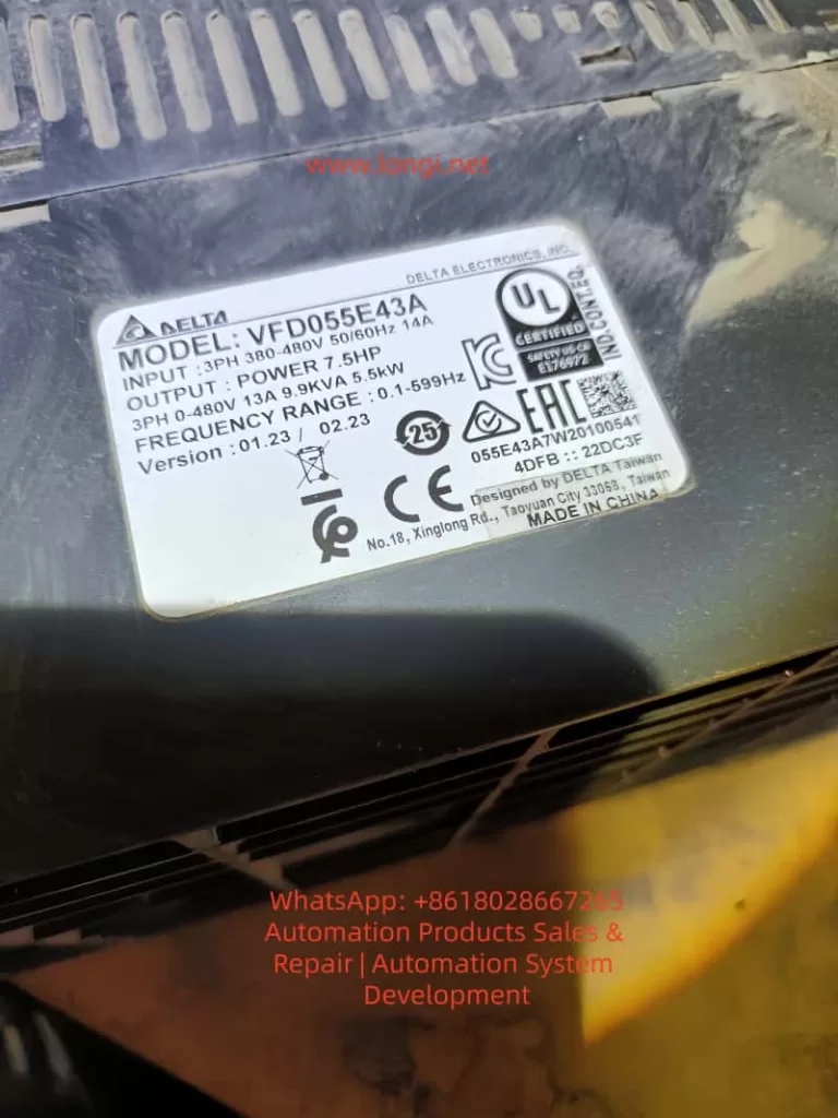
The Delta VFD-E series is a sensorless vector control micro-drive. With its built-in PLC, compact design, and high cost-effectiveness, it is widely used in industries like textiles, machine tools, packaging, and conveyor lines. However, a common frustration for field engineers is the “Err” message that appears on the digital keypad as soon as they try to change a setting.
Often, the engineer checks parameter Pr.00.02 (Parameter Management) and confirms it is set to 0 (allowing read/write access), yet the “Err” persists. This indicates that the inverter’s internal logic protection has been triggered by multiple layers of security. This article will analyze the technical details behind this phenomenon.
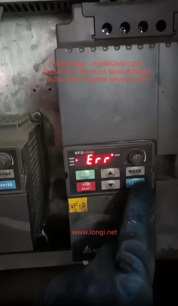
2. The Essence of the “Err” Message: Protection, Not Failure
In the context of Delta inverters, “Err” is fundamentally different from fault codes like “OC” (Overcurrent) or “OV” (Overvoltage). It is not an alarm for hardware damage but a Software Write-Refusal feedback.
Simply put, when the inverter’s microcontroller (MCU) determines that the current system environment does not meet the conditions for parameter modification, it intercepts the “WRITE” command from the keypad to prevent motor instability or equipment damage. It is crucial to understand: The error does not mean the inverter is broken; it means the inverter believes the current state is “unsuitable” for changes.
3. Dimension 1: Conflict Between Operation Status and Writing Timing
3.1 “Read-Only During Operation” Hard Limit
This is the most frequent cause of “Err,” accounting for over 70% of cases. For safety, Delta VFD-E parameters are categorized into two types:
- Dynamic Parameters: Can be modified during operation (e.g., frequency command, acceleration/deceleration time), usually marked with a $\triangle$ in the manual.
- Static Parameters: Must be modified while the motor is stopped (e.g., motor poles, base frequency, control mode).
If the inverter is in RUN mode (RUN light is on or blinking) and you attempt to change a static parameter, the system will instantly throw an “Err.”
3.2 Detection Criteria and Countermeasures
Even if the motor isn’t physically spinning, if the inverter has received a start signal from external terminals (even if the frequency is 0Hz), it is considered to be in an “Operating State.”
- Action: Press the STOP key on the keypad and ensure external control terminals (like MI1, MI2) are disconnected. Confirm the keypad display is static and the RUN light is off before modifying parameters.
4. Dimension 2: Deep Logic of Parameter Locking and Password Systems
4.1 Hidden Restrictions of Pr.00.02
While Pr.00.02 is the first gateway:
0: All parameters accessible.1: All parameters read-only (Writes trigger “Err”).8: Keypad operation disabled.
If 00.02 is 0 but you still see “Err,” a “Shadow Lock” is likely active.
4.2 The Password Logic of Pr.00.09 and Pr.00.08
The VFD-E series supports user-defined password protection defined by Pr.00.09.
- Mechanism: Once a non-zero value is set in
Pr.00.09(e.g., 1234), the inverter automatically locks all parameters upon the next power-up. - Unlocking: The user must enter
Pr.00.08(Password Input) and type the correct numerical code. If successful,Pr.00.08will return to0, granting permission to modify other parameters. - Error Characteristic: Attempting to change any parameter without unlocking via
Pr.00.08first will result in an “Err” because the inverter deems the user unauthorized.
4.3 The Cost of Forgotten Passwords
If a password is entered incorrectly three times, the keypad displays “codE” and deadlocks. You must power-cycle the unit to try again. If the password is lost, there is no conventional way to recover it; you typically need to contact Delta technical support for a factory-level reset.
5. Dimension 3: Logic Overriding by Digital Input Terminals (MI)
The multi-function input terminals (MI3-MI9) of the VFD-E are highly programmable. In complex control systems, an engineer might have defined a terminal as a “Parameter Lock.”
5.1 Parameter Lock Terminal (Function Code 17)
Check parameters Pr.04.05 through Pr.04.08 (corresponding to MI3 to MI6).
- If any of these are set to 17, that physical terminal becomes an “Electronic Lock.”
- Trigger Logic: As long as that terminal is closed with the common terminal (DCM), the inverter enters a global lock state. Any modification attempt from the keypad will return “Err.”
- Countermeasure: Inspect the wiring. Ensure no external signal is inadvertently triggering the lock. To test, temporarily set
04.05-04.08to0(No Function).
6. Dimension 4: Interference from Built-in PLC Mode and Communication Protocols
The VFD-E’s built-in PLC is a powerful feature, but it can interfere with manual settings.
6.1 PLC Run Mode Lock
If the built-in PLC is in RUN status (controlled by Pr.00.16 or a physical toggle switch), the PLC program might be continuously scanning and overwriting certain parameters. Manual changes during a PLC scan cycle often cause conflicts, resulting in “Err.”
- Solution: Set
Pr.00.16to0(Disable PLC) or flip the side PLC switch to the STOP position.
6.2 RS-485 Communication Lock
If the inverter is connected to a Master (PLC or HMI) via Modbus, the Master might be sending high-frequency write commands. This bus occupancy can push the keypad’s “Write” request to a lower priority or block it entirely.
- Solution: Unplug the communication cable (RJ-45) from the side of the inverter and try modifying the parameter manually.
7. Special Cases: Hardware Aging and Keypad Faults
Though rare, hardware issues can manifest as parameter write errors:
- Button Sticking: If the ENTER or arrow keys are faulty and generate jitter signals, the MCU may interpret this as an illegal operation and trigger “Err.”
- EEPROM End-of-Life: The internal EEPROM chip has a limit on write cycles (typically 100,000). If the chip fails, any attempt to save a new value will fail physically, often returning “Err” or “cFx.x” (Control Fault).
8. The Ultimate Solution: Forced Initialization and Parameter Recovery
If you have confirmed Pr.00.02=0, no password is set, no terminals are locked, and the PLC is stopped, yet “Err” persists, a Factory Reset is recommended.
8.1 Steps for Initialization
- Ensure the inverter is in STOP mode.
- Navigate to parameter Pr.00.02.
- Attempt to set the value to 9 (for 50Hz systems) or 10 (for 60Hz systems).
- Press ENTER.
- The display should show “END”, indicating all parameters have returned to factory defaults.
Note: If even the initialization returns “Err,” it is a definitive sign that either the password protection is still active or the mainboard has a hardware failure.
9. Preventive Measures: Building an Efficient Parameter Management System
To avoid future “Err” issues, adopt these management practices:
- Maintain a Parameter Backup Sheet: Always record the values of
00.02,00.09, and MI terminal definitions. - Use Software Tools: Use Delta’s VFDSoft software via a PC. The software interface provides much more detailed error descriptions than the 7-segment LED display.
- Tiered Access: Before handing over equipment to a client, lock the parameters via
Pr.00.02 = 1and document the unlocking process in the machine manual.
10. Conclusion
The “Err” message on a Delta VFD-E is not a technical dead-end but a manifestation of its robust self-protection logic. When 00.02 is already 0, the core of the problem usually lies in Operation State restrictions, Password verification in Pr.00.08, or Logic occupancy by MI terminals.
By following this comprehensive troubleshooting checklist, engineers can peel back the layers of interference. In industrial environments, logical rigor determines equipment stability. We hope this guide helps you resolve your parameter writing challenges swiftly.
Keywords: Delta Inverter, VFD-E, Parameter Error, Err Message, Pr.00.02, Inverter Password Reset, Industrial Automation, VFD Troubleshooting.