
Mapping Table, Register Offset, and Engineering Recovery Guide
1. Introduction: When Modbus Communication Is “Online” but All Data Is Wrong
In industrial water quality monitoring systems, the HACH SC1000 controller is widely used to integrate pH, conductivity, dissolved oxygen, turbidity, COD, ammonia, and multi-parameter probes into centralized monitoring platforms.
Most SC1000 installations communicate with PLCs, DCS systems, or industrial PCs through RS485 Modbus RTU.
A common and extremely misleading field problem is:
The serial port is online, Modbus polling works, no communication alarms appear —
yet the values on the control system are completely wrong.
Typical symptoms include:
- Some parameters always show 0
- One parameter shows a “reasonable” value but appears under the wrong variable
- Switching byte order suddenly produces very large or negative numbers
- No communication timeout or CRC error exists
This type of fault is often misdiagnosed as:
- Cable interference
- RS485 wiring error
- Baud rate or parity mismatch
- Sensor failure
However, in real engineering practice, if communication is stable but data is logically wrong, the root cause is almost never the physical layer.
It is almost always a Modbus register mapping structure problem.
This article provides a systematic engineering analysis based on a real SC1000现场案例, and explains:
- Why this problem happens
- How to identify it correctly
- How to recover the system
- How to prevent it permanently
2. Understanding SC1000 Modbus Architecture: Not a Fixed Register Device
Many engineers assume that the SC1000 has a “fixed Modbus register table” like most simple instruments.
This assumption is incorrect.
The SC1000 is a modular multi-parameter platform, not a single-function transmitter.
Its Modbus output is built from three layers:
- Sensor layer (pH, LDO, conductivity, turbidity, etc.)
- Internal variable layer (measurement, temperature, status words, warning codes, error codes)
- Modbus publishing layer (mapping table / telegram table)
Only the third layer defines what the external system can see.
The SC1000 does not simply expose one permanent register table.
Instead, it dynamically generates a Modbus mapping table according to:
- Installed sensor modules
- Active variables
- Engineering configuration
- Default regeneration or manual editing
This mapping table controls:
- Which variables are published
- The order of variables
- Register offsets
- Data types (float / int)
Once this table changes, the PLC or industrial PC must follow it exactly.
If the control system continues reading the old structure, the data becomes meaningless.
3. Typical Fault Characteristics of Mapping Table Failure
In the real case discussed, the control system showed:
- pH ≈ 7.689 (correct value)
- but it appeared under the wrong channel
- most other channels were 0
- changing data order produced huge or negative values
These symptoms form a very clear technical fingerprint.
3.1 Physical communication is normal
- No timeout
- No CRC alarm
- Stable refresh
- Values change consistently
This proves:
- RS485 wiring is fine
- Baud rate and framing are correct
- Modbus RTU frames are valid
3.2 Logical structure is broken
- Only one variable looks real
- Others are zero or impossible
- Changing byte order changes magnitude but not correctness
This proves:
- The data exists
- But registers are being interpreted using the wrong structure
This is a register mapping failure, not a communication failure.
4. The Root Cause: SC1000 Modbus Mapping Table Has Changed
When the SC1000 Modbus variable list was inspected, it showed entries such as:
0   Temperature        float
2   Error Code         int
3   pH                 float
5   pH                 float
7   Status Word        int
8   Device Warnings    int
9   Device Errors      int
10  pH                 float
Two facts are immediately obvious:
4.1 Registers are not continuous
Offsets are:
0, 2, 3, 5, 7, 8, 9, 10 …
This means the table includes:
- gaps
- integer diagnostic registers
- mixed data lengths
4.2 Data types are mixed
The table mixes:
- float measurement values
- int status words
- int warning codes
- int error codes
However, most engineering projects configure the PLC or IPC to read:
pH
temperature
conductivity
dissolved oxygen
turbidity
as continuous float values.
When the SC1000 mapping table reverts to a default or regenerated structure, while the control system still expects a continuous float table, the result is guaranteed misalignment.
This explains perfectly why:
- one pH value appears in the wrong variable
- all others become zero or nonsense

5. Why This Happens After “Just Viewing Parameters”
The SC1000 contains configuration functions such as:
- Default value settings
- Sensor reinitialization
- Module scanning
- Variable refresh
Any of the following actions may regenerate the Modbus table:
- Installing or removing a probe
- Entering and confirming default settings
- Saving sensor configuration
- Rebuilding internal variable lists
If the operator enters these menus and confirms with “OK”, the SC1000 may:
- rebuild its internal object list
- regenerate the Modbus publishing table
- restore factory mapping structure
Once this happens, the control system is immediately out of sync.
This is why many field failures occur suddenly after “only checking parameters”.
6. Systematic Engineering Troubleshooting Process
Step 1: Eliminate physical communication faults
Confirm:
- No Modbus timeout
- No CRC errors
- Stable refresh rate
- Values change logically
If true → proceed to logical structure analysis.
Step 2: Verify whether mapping misalignment exists
Indicators:
- One real value appears under wrong tag
- Many values are zero
- Switching byte order only changes magnitude
If present → mapping table problem confirmed.
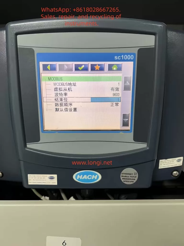
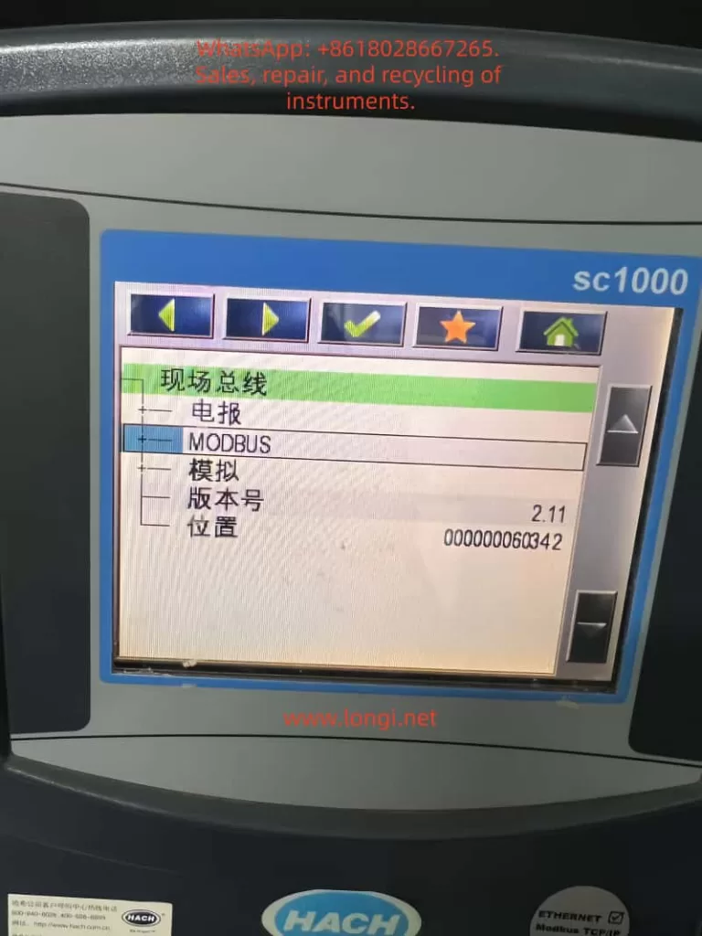
Step 3: Inspect SC1000 Modbus variable table
Navigate to:
Fieldbus → Modbus → Sensor → Variables / Telegram / Register list
Check:
- Offsets
- Order
- Data types
- Diagnostic registers presence
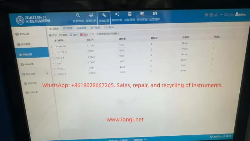
Step 4: Compare with PLC / IPC Modbus configuration
Confirm for each channel:
- Function code (03 / 04)
- Register address
- Data length (1 or 2 registers)
- Data type (float / int)
If PLC expects continuous floats while SC1000 outputs mixed types, misalignment is guaranteed.
7. Engineering Recovery Methods
Method A – Restore original SC1000 mapping (Recommended)
If any original documents exist:
- commissioning sheet
- Modbus register list
- integrator documentation
- screenshots
Use them to rebuild the SC1000 mapping:
- remove diagnostic registers
- publish only process values
- arrange continuous floats
This keeps the control system unchanged.
Method B – Rebuild a new engineering mapping table
If no documentation exists, rebuild on site.
Recommended industrial structure:
0   pH              float
2   Temperature     float
4   Conductivity    float
6   Dissolved O2    float
8   Turbidity       float
10  COD             float
Principles:
- Only process variables
- Only float
- Continuous order
- No status words
Once published, adjust PLC addresses to match.
Method C – Modify PLC Modbus configuration
This is least preferred.
It requires:
- remapping every channel
- reinterpreting data types
- rebuilding alarms and scaling
It increases long-term maintenance risk.
8. How to Prevent This Failure in Engineering Projects
8.1 Always export Modbus mapping tables
Every SC1000 project must include:
- printed mapping table
- Excel documentation
- commissioning photos
The Modbus table is as important as PLC code.
8.2 Treat “default settings” as dangerous operations
Default or regeneration functions should be restricted and documented.
8.3 Check mapping after probe replacement
Any sensor change may rebuild internal variables.
Mapping verification must become a maintenance step.
8.4 Establish dual-side backups
- SC1000 parameter backup
- PLC project backup
This prevents catastrophic configuration drift.
9. Conclusion
When HACH SC1000 Modbus communication shows:
- online communication
- wrong values
- variable displacement
- zero readings
the correct engineering conclusion is:
This is not a communication problem.
This is a Modbus mapping structure problem.
The SC1000 is not a fixed-register device.
Its Modbus output is an engineering-level data structure.
Once the mapping table changes, the control system must change with it — or the data becomes meaningless.
The real solution is not changing baud rate, cables, or parity.
The real solution is:
- inspecting the mapping table
- understanding register structure
- rebuilding engineering-grade Modbus telegrams.