
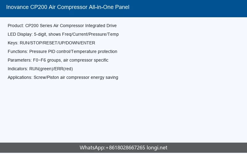
Inovance CP200 Series Air Compressor All-in-One Inverter User Guide: Operation Panel, Terminal Control and Fault Troubleshooting
The Inovance CP200 series is a specialized air compressor all-in-one inverter developed by Inovance Technology. Unlike conventional standalone inverters, the CP200 integrates a variable-frequency drive, a fixed-frequency fan contactor, a 220V AC power supply, a 24V external output, and dedicated protection circuits for PT100 and PTC sensors into a single compact unit. This design significantly simplifies installation and wiring for air compressor manufacturers while providing comprehensive control and monitoring capabilities for compressor operation. This guide provides practical information for operators, installers, and maintenance personnel on using the CP200’s operation panel, connecting control terminals, configuring parameters, establishing communication, and troubleshooting fault conditions.
1. Product Overview
The CP200 series is designed specifically for air compressor applications, combining inverter and compressor control functions into one device. The unit supports wall-mounted installation with a plastic enclosure and features plug-in control terminals with anti-misinsertion design to simplify field wiring. Available models cover the 5.5kW to 15kW range: CP200-4T5.5-H, CP200-4T7.5-H, CP200-4T11-H, and CP200-4T15-H.
Key integrated features include a built-in 220V AC power supply, 24V DC external output (maximum 500mA), a fixed-frequency contactor for the cooling fan, and built-in detection and protection circuits for PT100 temperature sensors and PTC thermal protection. The control software is purpose-built for compressor applications, enabling one-button startup when connected to HMI or IoT devices without additional commissioning. The inverter supports sensorless vector control (SVC) and V/f control, with an output frequency range from 0Hz to 500Hz and a carrier frequency adjustable between 2kHz and 8kHz (default 6kHz).
The main power terminals use a bottom-in/bottom-out configuration. Input power connects to terminals R, S, and T, while the main compressor motor connects to U1, V1, and W1. The fixed-frequency cooling fan motor connects to U2, V2, and W2. The unit includes three LED indicators on the front panel for power status, run status, and fault status, providing immediate visual feedback on system state.
2. LED Operation Panel and HMI Interface
2.1 Built-in LED Indicators
The CP200 chassis features three LED indicators that provide at-a-glance status information. The green power indicator illuminates when the unit is energized, confirming that the control power supply is active. The green run indicator lights when the inverter is actively driving the compressor motor. The red fault indicator illuminates whenever the system detects an alarm or fault condition that requires attention. These LEDs are positioned on the front panel for easy visibility during routine inspections.
2.2 SOP-20-CP Intelligent Operation Keypad
For detailed parameter access and advanced commissioning, the optional SOP-20-CP intelligent operation keypad serves as the primary human-machine interface. This LCD-based keypad features a 240×160 pixel monochrome display with white backlighting and supports multiple fieldbus connections. The keypad can be mounted directly on the inverter or installed remotely on a cabinet door using the provided mounting kit, with IP20 protection as standard and an optional IP54 kit available for harsh environments.
The keypad interface is divided into several zones: the status area at the top displays current device state and any active fault messages; the device information area shows the current station number and device name; the content area provides real-time monitoring data; the device list allows navigation between multiple connected units; and the clock displays the current time. A menu button provides access to all functional parameter groups.
2.3 Keypad Buttons and Functions
The SOP-20-CP keypad includes several dedicated buttons. The left and right soft keys function as cancel/exit and select/confirm respectively. The run and stop buttons control motor operation in local control mode, with the stop button also serving as a fault reset when the system is in a fault state. The LOC/Rem toggle switches between local keypad control and remote terminal or communication control. Directional arrows navigate menus, scroll text, and move the cursor during parameter editing. A help key opens context-sensitive help pages related to the current menu or view.
Several keyboard shortcuts enhance efficiency. Pressing left and up arrows simultaneously adjusts backlight brightness, while left and down arrows adjust display contrast. The combination of left arrow plus help key adds the currently selected parameter to a quick-debug page for fast access during commissioning. Users can also add parameters to a startup display page for monitoring preferred values immediately after power-on.
2.4 Connecting the Keypad to a PC
The SOP-20-CP includes a Mini-USB B-type connector for connection to a PC using a cable no longer than 3 meters. When connected, users can select between USB relay mode, which enables PC-based commissioning tools (InoDriveStudio) to communicate with the inverter through the keypad, or USB mass storage mode, which allows file operations on the keypad’s SD card. The SD card stores manufacturer parameters, real-time operational data logs for fault diagnosis, user programs, and firmware updates for the keypad or inverter.
3. Terminal Control and Wiring
3.1 Main Circuit Terminals
The main power circuit uses bottom-entry, bottom-exit terminal arrangement. The R, S, and T terminals receive three-phase AC input power (380V to 440V, 50/60Hz). The U1, V1, and W1 terminals deliver variable-frequency three-phase power to the main compressor motor. The U2, V2, and W2 terminals provide fixed-frequency three-phase power to the cooling fan motor. A dedicated PE terminal ensures proper safety grounding. For installations on 480V grid systems, the fixed-frequency transformer must be replaced, which requires contacting Inovance service engineers.
3.2 Control Terminal Layout
The control terminals are arranged on a dedicated control board and use plug-in connectors with anti-misinsertion design. The terminal functions are organized into several categories:
- Relay Output (T1A, T1C): Normally-open relay output rated for 220V AC at 50VA, factory-configured for solenoid valve control.
- Pressure Sensor Input (P1+, P1-): 24V DC powered, 4mA to 20mA active input with 12-bit resolution and 0.5% calibration accuracy for the system pressure transducer.
- Temperature Sensor Inputs (PT1+, PT1-, PT2+, PT2-): Passive inputs for PT100 resistance temperature detectors, covering a range of -25°C to +220°C with ±3°C accuracy.
- Digital Inputs (DI1-DI3): Isolated sink inputs with input frequency below 100Hz. DI3 additionally supports PTC protection with trip resistance of 2.3kΩ.
- 24V Power Output (+24V, COM): Provides 24V DC ±10% at maximum 500mA for external devices such as HMIs or sensors.
- RS485 Communication (RJ45): Half-duplex RS485 with baud rates up to 230kbps for Modbus or other communication protocols.
3.3 Wiring Recommendations
Control cables must be routed separately from main power cables to prevent electromagnetic interference. Shielded twisted-pair cables are required for control signals, with the shield connected to the inverter’s grounding terminal at one end only. All control signal wiring should be secured with cable ties near the interface to maintain reliable connections under vibration.
After completing all wiring, a systematic inspection checklist must be followed: verify input power is connected to R/S/T (not output terminals), confirm motor wiring connects to U1/V1/W1, check cable gauge compliance, ensure heat-shrink tubing fully covers conductor portions at terminals, verify motor cable length does not exceed 50m without reducing carrier frequency, confirm proper grounding, tighten all terminal screws, verify control cables use shielded twisted pairs, and ensure control cables are separated from power cables in routing.
3.4 Grid System Requirements
The CP200 is designed for TN/TT grounded neutral grid systems. When used on IT systems (ungrounded or high-resistance grounded), the varistor (VDR) jumpers must be removed to prevent potential hazards or inverter damage. The varistor and EMC capacitor jumpers are located on the unit as indicated in the installation manual, and their removal must be performed by qualified personnel before energizing the inverter on IT systems.
4. Parameter Settings and Password Management
4.1 Parameter Groups Overview
The CP200 organizes parameters into functional groups identified by letter codes. The F0 group contains fundamental operating parameters including control mode selection, run command source, frequency source, acceleration/deceleration times, and carrier frequency. The F1 group stores motor parameters including rated power, voltage, current, frequency, and speed, as well as encoder configuration if applicable. The F2 group configures vector control parameters including speed loop gains, torque limits, and flux-weakening settings. The F3 group contains V/f control parameters, overcurrent and overvoltage stall suppression settings, and oscillation suppression parameters. The F4 group defines digital input terminal functions, analog input curves, and filtering parameters. Air-compressor-specific parameters are grouped in the A8 series, covering pressure and temperature protection thresholds, PID settings, and maintenance timer configurations.
4.2 Critical Parameters for Commissioning
Several parameters require careful attention during initial setup. Parameter F0-01 selects the motor control mode: 0 for sensorless vector control (SVC, default) or 2 for V/f control. Parameter F0-02 selects the run command source: 0 for keypad, 1 for terminals, 2 for communication, or 3 for custom. Parameter F0-03 selects the main frequency source; for compressor applications, the default value of 11 selects the dedicated air compressor process frequency source. The maximum frequency (F0-10) defaults to 155Hz, while the upper frequency limit (F0-12) also defaults to 155Hz and the lower frequency limit (F0-14) defaults to 40Hz.
Motor parameters in the F1 group must match the nameplate data of the connected compressor motor exactly. Parameter F1-00 selects the motor type: 0 for standard induction motor, 1 for variable-frequency induction motor, or 2 for permanent magnet synchronous motor (default). Parameters F1-01 through F1-05 set the rated power, voltage, current, frequency, and speed. After entering motor parameters accurately, an automatic motor parameter identification procedure should be performed using parameter F1-37 to optimize control performance.
4.3 Password Protection and Access Levels
The CP200 implements a password system to prevent unauthorized parameter modifications. When accessing certain parameter groups through the HMI or keypad, the system prompts for password entry. The user parameter group requires entry of the correct password to modify host and fan-related settings. Higher-level parameter groups, including manufacturer parameters, require additional authentication. Password entry is performed through a numeric input dialog, with ENT confirming entry and CR canceling. Incorrect passwords deny access and require re-entry. Maintenance personnel should ensure authorized users retain current passwords while protecting them from unauthorized access.
4.4 Parameter Initialization and Backup
The system supports parameter initialization to restore factory defaults, which is useful when commissioning unknown equipment or recovering from misconfiguration. The parameter backup function allows saving the current parameter set to the keypad’s SD card or internal memory, enabling rapid restoration or duplication of settings across multiple units. Parameter changes can be configured for real-time or stop-only modification depending on the parameter’s criticality to system operation.
5. Communication and Multi-Unit Coordination
5.1 RS485 Modbus Communication
The CP200 includes standard RS485 communication via the RJ45 connector on the control terminal board. The default protocol is Modbus RTU, selectable through parameter F0-31 (0 for Modbus, 1 for extended protocol). The communication baud rate, data format, and station address are configured through the FD parameter group. The RS485 interface supports baud rates up to 230kbps in half-duplex mode.
Typical wiring uses the RJ45 connector with 485+ and 485- signals. For reliable communication, use shielded twisted-pair cables and connect the shield to ground at one end only. The maximum recommended cable length depends on baud rate, with lower rates supporting longer distances up to approximately 1200 meters at 9600bps. Proper termination resistors should be installed at the network ends for multi-drop configurations.
Modbus communication enables remote monitoring of all operational parameters, remote start/stop commands, frequency reference setting, and fault status reading. The communication address mapping follows standard Modbus conventions, with each parameter accessible at its defined address. For example, parameter F0-00 corresponds to Modbus address 0xF000, F0-01 to 0xF001, and so on through the parameter group structure.
5.2 CANopen and CANlink Support
Beyond Modbus, the CP200 supports CANopen and CANlink protocols for more demanding multi-axis or multi-unit applications. CANopen configuration uses parameters in the AF group for PDO mapping and heartbeat timing. The CANlink protocol supports station number configuration through parameter FD-02, with a heartbeat timeout function to detect communication interruptions. When multiple units operate on the same CAN bus, ensure each unit has a unique station address to prevent conflicts.
5.3 Multi-Unit Master-Slave Operation
For air compressor systems requiring multiple drives, the CP200 supports master-slave control through CAN bus. In this configuration, the master unit coordinates slave units, and if a slave detects a fault, it reports the condition to the master through CAN communication. The master then triggers fault E55.01 (master-slave slave fault) and executes the configured response. Commissioning master-slave systems requires careful configuration of the communication parameters, station addresses, and fault response levels on all participating units.
5.4 Communication Faults
Communication-related faults include E.160.01 for Modbus timeout, E.161.01 for CANopen heartbeat timeout, E.161.02 for CANopen PDO mapping errors, E.162.01 for CANlink heartbeat timeout, and E.162.02 for CANlink station number conflicts. When any communication fault occurs, first verify physical cable connections, check that the communication parameters (baud rate, station address, format) match between all devices, confirm the communication cycle time setting (FD-04 for Modbus) is appropriate for the network load, and inspect for electromagnetic interference on the communication lines.
6. Fault Codes and Troubleshooting
6.1 Fault Level System
The CP200 employs a multi-level fault classification system ranging from level 0 (free stop) to level 7 (no fault). Level 0 triggers an immediate coast-to-stop. Level 1 performs maximum capability deceleration. Level 2 executes fast deceleration. Level 3 performs controlled deceleration to stop. Level 4 restricts operation with reduced capability. Level 5 generates a warning while continuing operation. Level 6 provides informational prompts only. Level 7 disables the fault entirely. Most critical faults default to level 0, while warnings and pre-fault conditions may default to level 5 or 6 depending on severity.
6.2 Overcurrent and Overvoltage Faults
E02.01 Hardware Overcurrent: Occurs when instantaneous output current exceeds 2.5 times the rated inverter current multiplied by 1.414. Common causes include output ground faults, phase-to-phase shorts, missing motor parameter identification under vector control, encoder interference or disconnection, output phase loss, or incorrect inverter model selection (FF-01). Troubleshooting involves checking motor and cable insulation with a megohmmeter, verifying encoder connections and shield grounding, confirming proper motor parameter configuration, and ensuring the correct inverter model code is set.
E02.02 Software Overcurrent: Triggered when current exceeds the software overcurrent threshold (default 100% of full-scale, equivalent to 2.2 times rated current times 1.414). Investigation follows the same methodology as hardware overcurrent, with additional attention to V/f control acceleration/deceleration times that may be set too aggressively.
E05.01 Overvoltage: The DC bus voltage exceeds the overvoltage threshold set in A5-06. Frequent causes include motor regenerative power during deceleration, incorrect braking resistor selection, braking resistor disconnection, or vector control overshoot during speed settling. Enable overvoltage suppression (F3-19 for V/f, AB-25 bit1 for vector) if no active load is present. Verify braking resistor sizing and connections.
E09.01 Undervoltage: DC bus voltage falls below the undervoltage threshold. Check for input power interruption or voltage sag, verify input voltage is within the 342V to 418V range, inspect for input phase loss, and confirm the undervoltage threshold setting (A5-06) is appropriate. If the DC bus voltage does not measure approximately 1.414 times the AC input voltage, internal rectifier or control board faults may be present.
6.3 Overload and Thermal Faults
E10.01 Drive Overload: The inverter output current exceeds the overload curve threshold. Reduce the mechanical load, check for motor bearing seizure, verify the carrier frequency is not set excessively high above the F0-15 default, and confirm the inverter power rating is adequate for the motor. For prolonged operation below 5Hz at heavy load, consider selecting a larger inverter as derating requirements apply.
E11.01 Motor Overload: The motor current exceeds the motor-specific overload curve. Check whether motor protection parameter F9-01 is appropriately configured (default 1.0). Reduce mechanical load and inspect the compressor mechanical system for binding or excessive resistance.
E14.01 Drive Overheat: The heatsink temperature exceeds the thermal limit. Verify ambient temperature is below 40°C (derate 1.5% per degree above 40°C up to 50°C), ensure cooling airflow is unobstructed, confirm cooling fan operation, and check whether the heatsink is clogged with dust or debris. If the temperature continues rising or fails to decrease after one hour of shutdown, the thermal sensor or power module may be defective.
6.4 Sensor and Peripheral Faults
E70.00 Pressure Sensor 1 Warning / E71.00 Pressure Sensor 1 Overpressure: These faults indicate the pressure sensor 1 reading has exceeded the warning threshold (A8-11) or protection threshold (A8-10). Common causes include incorrect pressure sensor wiring, mismatched pressure range settings (A8-05), improperly configured alarm thresholds, sensor malfunction, incorrect pressure calibration (AC-0B or A8-41), or a closed discharge valve. Resolution steps include verifying wiring, matching the pressure range setting to the sensor rating, adjusting protection thresholds to application requirements, and replacing defective sensors.
E72.00 Temperature Sensor 1 Overtemperature / E73.00 Temperature Sensor 1 Warning: These indicate the temperature sensor 1 reading has exceeded the protection threshold (A8-12) or warning threshold (A8-13). Investigate whether temperature and pressure sensor wiring was accidentally swapped, verify adequate cooling airflow and fan rotation, check lubricant level and quality, clean the radiator of dust and foreign material, and inspect return oil lines for blockages. Calibration parameters AC-17 and A8-42 should also be verified.
E74.00 Pressure Sensor Disconnection / E75.00 Temperature Sensor Disconnection: The system detects a sensor wiring break when the analog input reads 0.1V or less for 10 seconds (pressure) or when temperature exceeds 222°C for over 1 second (temperature). Check sensor wiring continuity and replace faulty sensors.
6.5 Compressor-Specific Faults
E76.00 through E80.00 (Maintenance Warnings): These warnings indicate that operating hours for the air filter (E76), oil filter (E77), oil-gas separator (E78), motor grease (E79), or lubricating oil (E80) have reached the configured maintenance intervals (default 2000 hours). Perform the required maintenance and reset the corresponding runtime counter to clear the warning.
E82.01 Oil-Gas Separator Clogging / E83.00 Separator Clogging / E84.01 Oil Filter Clogging / E85.01 Air Filter Clogging: These faults activate when the corresponding digital input configured for clogging detection (functions 53, 54, 55, 56 via F4-00 to F4-05) receives a closed contact signal. Inspect and clean or replace the affected component, then verify the DI terminal function assignment matches the actual wiring.
E95.00 Solenoid Valve Short Circuit: Detected when solenoid current exceeds 1A for 4ms, occurring 60 times within 1 second. Verify the solenoid valve voltage rating matches the built-in transformer output (110V or 220V AC), check valve coil integrity, and measure the current draw. If current remains excessive after valve replacement, the inverter’s relay output circuit may require service.
E96.00 Phase Sequence Error: Triggered when the three-phase input voltage angle deviation is less than -5.5 degrees with voltage above 200V for more than 5 seconds. Correct the input phase sequence by swapping any two of the R, S, T input phases, and verify phase voltage imbalance does not exceed 30V.
E97.00 Fixed-Frequency Fan Phase Loss: The fan output current imbalance exceeds ten times between maximum and minimum phases, with the maximum exceeding 12% of the fan rated current. Check fan motor wiring, measure phase resistances to detect open windings, verify fuse integrity, and if the inverter outputs unbalanced phase voltages even with the fan disconnected, the inverter power stage may be defective.
6.6 General Troubleshooting Procedure
When any fault occurs, follow a systematic approach. First, observe the fault code displayed on the keypad or HMI and record it. Check the fault indicator LED if the keypad is not connected. Review the fault level to understand whether the system performed an immediate stop, controlled deceleration, or continued operation with warning. Attempt a fault reset using the stop button on the keypad or a configured digital input after confirming the fault condition has been resolved. If the fault reoccurs immediately, the underlying cause has not been corrected. For faults that cannot be reset or recur persistently after addressing apparent causes, consult the detailed fault description in the manual’s fault code section and contact Inovance technical support if internal inverter damage is suspected.
7. Conclusion
The Inovance CP200 series all-in-one inverter provides a highly integrated solution for air compressor control, combining variable-frequency motor control, fixed-frequency fan management, sensor interfaces, and compressor-specific logic in a single compact unit. Successful operation depends on proper wiring of main power and control terminals, accurate motor parameter configuration, appropriate pressure and temperature protection thresholds, and reliable communication setup when remote monitoring or control is required. Understanding the fault code system and following structured troubleshooting procedures minimizes downtime and ensures safe, efficient compressor operation. Regular maintenance according to the integrated service timers maintains system reliability and prevents unexpected interruptions.