Posted on

CM-SVC Servo Manual User Guide: In-depth Analysis Based on Donghua Machinery Injection Molding Machine Applications

I. Introduction

In the field of plastic injection molding equipment, the application of servo oil pump technology has become a core indicator for measuring the energy efficiency rating and dynamic response performance of injection molding machines. Donghua Machinery Co., Ltd., as a key enterprise in the domestic injection molding machine industry, utilizes the CM-SVC series servo drives as a dedicated product developed specifically for servo oil pump driving. Based on the technical content of the “CM-SVC Servo Drive Operation Guide Manual” and combined with the operational characteristics of Donghua Machinery injection molding machines in actual production, this user guide is compiled to assist field engineers, equipment maintenance personnel, and process debugging personnel in better mastering the entire process of installation, debugging, parameter optimization, and troubleshooting of this servo system.

CML drives

II. Technical Positioning of CM-SVC Servo Drive and Its Adaptability to Donghua Machinery

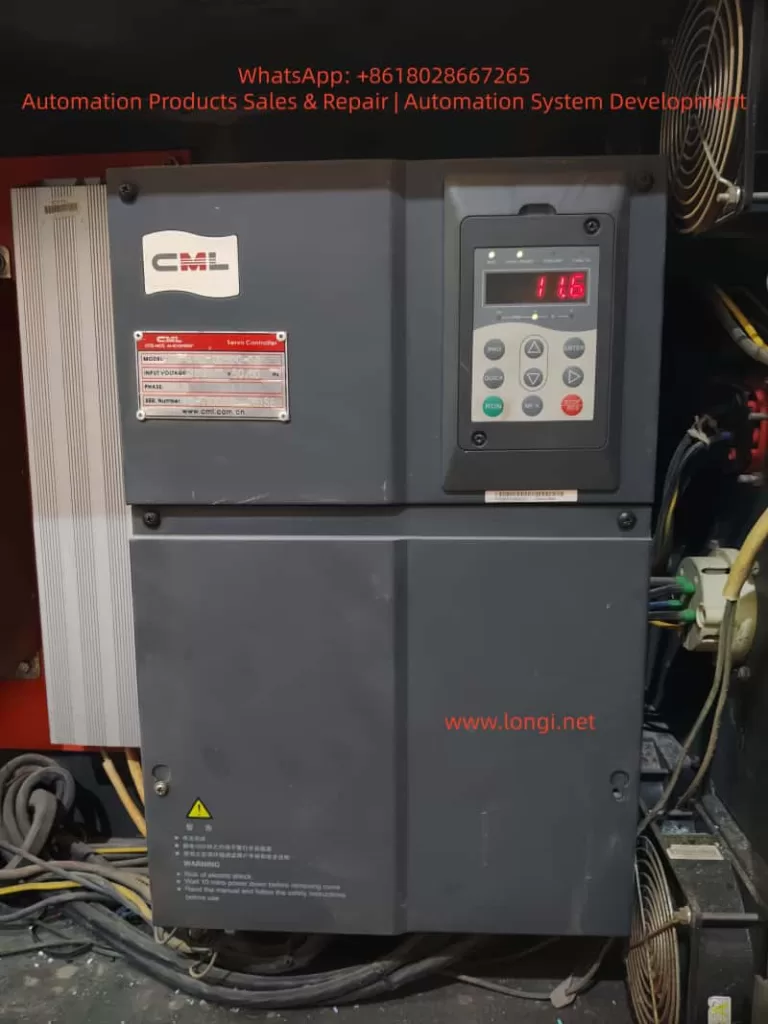
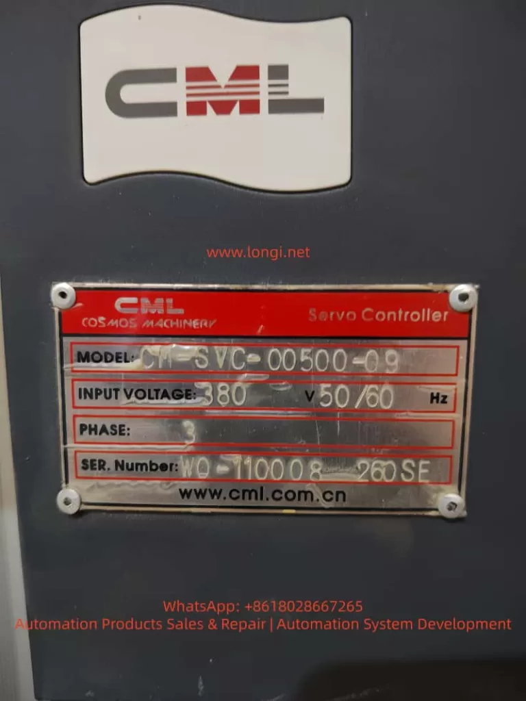
The CM-SVC series servo drives have a rated current coverage ranging from 15A to 300A and are compatible with three-phase 380V power supplies, capable of stable operation within a voltage fluctuation range of -15% to +20%. This series of drives is specifically designed for servo oil pump control scenarios and incorporates a built-in oil pressure closed-loop control algorithm, CAN communication interface, dual analog input channels, and multi-group PID parameter switching functionality, making it highly compatible with Donghua Machinery’s commonly used hydraulic system architecture of quantitative pump + servo motor + pressure sensor.

Donghua Machinery’s injection molding machine product line covers a clamping force range from 80 tons to over 3000 tons, with its hydraulic systems generally adopting a “flow-pressure dual closed-loop” control strategy. Under this system, the CM-SVC drive can operate in two typical oil pressure control modes:

  • Mode 2 (A3-00=2): Analog input method. The AI1 channel receives the oil pressure command (0~10V) from the controller (computer), the AI2 channel receives the flow command (0~10V), and the AI3 channel receives the actual feedback signal from the pressure sensor. This method is suitable for most standard models, offering fast signal response and strong anti-interference capability.
  • Mode 1 (A3-00=1): CAN communication input method. Oil pressure and flow commands are transmitted through the CAN bus, with AI3 still serving as the pressure feedback channel. This method is more suitable for large or high-speed models, reducing attenuation and interference of analog signals during long-distance transmission.

Understanding the differences between these two operating modes is fundamental to correctly using this manual. The following sections will provide detailed explanations centered around actual installation, debugging, and operational maintenance.

III. Key Points for Mechanical Installation and Suggestions for Donghua Electrical Cabinet Layout

3.1 Installation Environment Requirements

According to the content in Chapter 1 and Chapter 3 of the manual, the CM-SVC servo drive must be installed under the following environmental conditions:

  • Ambient temperature: -10°C to +40°C. If the temperature exceeds 40°C but does not exceed 50°C, derating must be applied.
  • Altitude: Below 1000m. Derating is also required if this altitude is exceeded.
  • Relative humidity: Less than 95%, non-condensing.
  • Absence of corrosive gases, flammable gases, oil mist, and conductive dust.

In Donghua Machinery’s actual production workshops, injection molding machines are usually arranged in a centralized manner, and the ambient temperature in summer may approach the upper limit of 40°C. Therefore, the following points should be noted during electrical cabinet design:

  1. Heat Dissipation Space: For drives with power ratings of CM-SVC-00400 and above, when installed vertically, the clear distance A between two sets of drives above and below should be greater than 50mm, and heat-insulating deflectors should be added. For models CM-SVC-00700 and above, A should be greater than 300mm.
  2. Metal Dust Protection: During plastic processing, fine dust may be generated, especially from materials with fillers (such as glass fiber, calcium carbonate). The manual specifically points out that for applications involving metal dust, it is recommended to adopt an external installation method for the radiator. This means extending the heat dissipation part of the drive outside the electrical cabinet while keeping the cabinet sealed.
  3. Vibration Isolation: The manual requires that vibration should not exceed 0.6G and specifically reminds to keep away from punching machines and other equipment. For large injection molding machines, although the impact from the injection unit and clamping unit is not significant, the drive should not be directly installed on the oil tank cover or frame but should be fixed on an independent electrical cabinet backplate welded with reinforcing ribs.

3.2 Lower Cover Removal and Wiring Space

Figure 3-2 in the manual illustrates the removal method of the metal shell lower cover. During actual wiring, it is recommended to first remove the lower cover, complete the main circuit and control circuit wiring, and then reinstall the cover. For models CM-SVC-01400 and above, the main circuit copper bar terminals are relatively large, and sufficient wrench space (recommended not less than 150mm) should be reserved.

CM-SVC-00500-09

IV. Engineering Guidance for Electrical Wiring

4.1 Key Points for Main Circuit Wiring

Section 3.2.4 of the manual details the terminal definitions of the main circuit and wiring precautions. Combined with Donghua Machinery’s typical configuration, the following key points are emphasized:

  1. Input Power R, S, T: There is no phase sequence requirement, but it must be connected through a circuit breaker and contactor. Table 3-1 in the manual provides recommended values for circuit breakers, contactors, and wire cross-sections for each model. For example, for CM-SVC-00500, a 125A circuit breaker, 100A contactor, 16mm² input wire, and 10mm² output wire are recommended. On-site wiring must not be lower than this standard.
  2. External DC Reactor: For models CM-SVC-01400 and above, an external DC reactor is标配(中文应为“标配”意思是 standard configuration,这里按原文保留英文不译更好,即标配用英文“standard”表达更准确,以下按此处理) standard. During installation, the short-circuit copper bar between P and (+) terminals must be removed, and the reactor must be connected in series between P and (+). This is a common error-prone point. If the copper bar is not removed, the reactor is bypassed, leading to increased input harmonics, reduced power factor, and potentially damaging the rectifier module in severe cases.
  3. Brake Resistor Wiring: For models CM-SVC-00500 and below with built-in brake units, the brake resistor is connected between (+) and PB. The resistance value must not be less than the recommended value in Table 2-6 of the manual; otherwise, the brake unit may be burned. For example, for CM-SVC-00300, the recommended resistance value is ≥32Ω, with a power of ≥1000W. The wiring distance should be less than 5m, and twisted-pair wires should be used.
  4. Output Side U, V, W: It is strictly prohibited to connect capacitors or surge absorbers. When the motor cable length exceeds 100m, an AC output reactor must be added. Donghua Machinery’s large models (such as those above 1300 tons) sometimes place the electrical control cabinet and oil pump motor separately, with distances possibly exceeding 50m. Although not reaching 100m, it is still recommended to evaluate whether to add a reactor based on the actual site conditions to reduce leakage current and motor insulation stress.

4.2 Key Points for Control Circuit Wiring

The control terminals serve as the bridge between the servo drive and the injection molding machine controller (computer). Table 3-3 in the manual provides a detailed description of terminal functions. The following lists the most commonly used wiring schemes:

  • +10V-GND: Provides 10V power externally, with a maximum of 10mA, for connecting external potentiometers (1kΩ~5kΩ). In analog input mode, potentiometers are generally not used; instead, a 0~10V signal is directly output by the controller.
  • AI1-GND: Default pressure setting. In Mode 2, it receives the oil pressure command signal output by the controller.
  • AI2-GND: Default flow setting. In Mode 2, it receives the flow command signal output by the controller.
  • AI3-GND: Pressure sensor feedback signal. Shielded twisted-pair wires must be used, with the shield grounded at the drive side. The sensor is usually of a four-wire system (power +, power -, signal +, signal -), with signal + connected to AI3 and signal – connected to GND.
  • +24V-COM: Provides 24V power externally, with a maximum of 200mA. It is used for dry contact input of DI terminals.
  • DI1-COM: Digital input 1, with the factory default function being forward rotation (FWD), i.e., the oil pump enable signal. Donghua Machinery’s controller usually outputs a passive contact signal connected between DI1 and COM.
  • DI4-COM: Default function is fault reset (RESET), connected to the reset output of the controller.
  • T/A1-T/C1: Relay output, with the default function being fault output. When the drive experiences a fault, this relay operates, providing a switch signal to the controller for shutdown protection.

Section 3.2.5 of the manual also provides solutions when the analog input terminals are interfered with: use shielded cables, keep the wiring distance within 20m, and add filter capacitors and ferrite cores if necessary. At the injection molding machine site, there are many electromagnetic interference sources such as frequency converters, contactors, and relays, making these measures very necessary.

V. Detailed Explanation of Parameter Setting and Debugging Process

5.1 Motor Parameter Tuning (Motor Identification)

This is a prerequisite for the normal operation of the servo system. Chapter 7 of the manual provides detailed tuning steps. At Donghua Machinery’s site, the following sequence should be followed:

  1. Correctly input the motor nameplate parameters: F1-00 (motor type, select 2 for permanent magnet synchronous), F1-01 (rated power), F1-02 (rated voltage), F1-03 (rated current), F1-04 (rated frequency), F1-05 (rated speed).
  2. Set A1-04 (resolver pole pairs), usually 1 pair or 2 pairs, as provided by the motor manufacturer.
  3. Set A3-00=0 (non-oil pressure control mode), F0-02=0 (operation panel control).
  4. If the back EMF (F1-15) is known, perform static tuning (F1-16=1). The motor can be loaded (not disconnected from the oil pump), but it is recommended to open the relief valve to allow the motor to operate under no-load or light-load conditions.
  5. If the back EMF is unknown, dynamic tuning (F1-16=2) must be performed. At this time, the motor must be disconnected from the load (i.e., the motor shaft disconnected from the oil pump); otherwise, the tuning results will be inaccurate, affecting subsequent speed control and pressure stability.

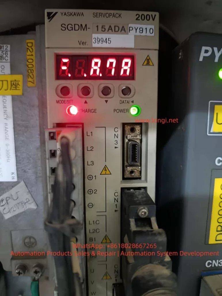
During tuning, if ERR43 (encoder fault) occurs, check the encoder wiring and A1-04 pole pair setting. After successful tuning, parameters such as F1-10 to F1-15 and A1-02 will be automatically filled in.

5.2 Oil Pressure Control Mode Switching and Automatic Parameter Setting

When switching from non-oil pressure mode (A3-00=0) to oil pressure mode (A3-00=1 or 2), the parameters listed in Table 7-4 of the manual will be automatically set. This means that users do not need to manually modify parameters such as F0-01 (control mode), F0-02 (command source), F4-00~F4-04 (terminal functions), as the system will automatically configure them to recommended values.

However, it should be noted: after automatic setting, if the user manually modifies these parameters again and wishes to retain them, their rationality must be confirmed. For example, F0-17 (acceleration time 1) and F0-18 (deceleration time 1) will be set to 0.0s. This is because in oil pressure control mode, acceleration and deceleration are actually determined by the oil pressure PID and flow command, rather than traditional acceleration and deceleration times. If users do not understand this, they may mistakenly believe that the parameters are lost.

5.3 Core Process Parameter Setting

The following parameters directly affect the action quality of the injection molding machine and need to be adjusted based on the actual mold and process:

  • A3-01 (maximum speed): Corresponds to the motor speed when the flow command is 100%. It is recommended to be set within 140% of the motor’s rated speed. For example, if the rated speed is 1500rpm, the maximum speed can be set to 2100rpm. After exceeding 150% of the rated speed, the motor torque decreases sharply, which is unfavorable for pressure holding.
  • A3-02 (system oil pressure): The highest working pressure set for the injection molding machine, in kgf/cm². For example, 175kgf/cm² (approximately 17.2MPa).
  • A3-03 (maximum oil pressure): The range of the pressure sensor, which should be consistent with the sensor’s nominal value. For example, if the sensor range is 250kgf/cm² (corresponding to 0~10V output), then A3-03=250.0.
  • A3-04 (oil pressure command rise time): Filters the oil pressure command signal, in ms. A smaller value results in faster response, but too small a value may cause pressure overshoot. It is generally set to 20~50ms.
  • A3-05~A3-07 (first group of PID): Proportional gain Kp, integral time Ti, and derivative time Td. This is the most commonly used set of PID parameters. Increasing Kp or decreasing Ti can improve response speed, but excessive values may cause oscillation. Donghua Machinery’s typical value range: Kp=150~300, Ti=0.05~0.20s, Td is generally set to 0 or a very small value.
  • A3-08 (maximum reverse speed): The maximum reverse speed during pressure relief, in percentage of the maximum speed. For example, if set to 50%, the reverse speed does not exceed half of the maximum speed. Reverse rotation is used for rapid pressure relief, but excessive values may cause oil pump reverse rotation noise and even damage the oil pump.
  • A3-09 (bottom flow): Minimum flow setting, as a percentage of the maximum speed. It is used to overcome internal leakage of the oil pump and prevent air from entering the oil circuit. It is generally set to 0.5%~3%.
  • A3-10 (bottom pressure): Minimum pressure setting, in kgf/cm². It is also used to maintain positive pressure in the oil circuit and is generally set to 0.5~2.0kgf/cm².

5.4 Multi-group PID Switching Logic

The manual provides four groups of oil pressure PID parameters, which can be switched through the digital state combination of DI2 and DI3. Table 7-2 shows the combination relationship. During the actual injection molding process, different DI combinations can be output by the controller to switch PID groups based on different requirements for pressure response in different actions (such as rapid injection, pressure holding, plasticizing, and cooling). For example:

  • Rapid injection stage: Fast response is required, so the first group with larger Kp and smaller Ti can be selected.
  • Pressure holding stage: Good stability and no overshoot are required, so the second or third group with moderate Kp and larger Ti can be selected.

This function requires the controller to support multiple DO outputs and to perform segmented PID scheduling in the program.

5.5 AI Zero-drift Automatic Calibration

Zero-drift inevitably exists in pressure sensor and controller-output analog signals. The manual provides a very practical function: set A3-20 to 1, and the drive will automatically detect the zero-drift values of AI1, AI2, and AI3 and write them to F4-18, F4-23, and F4-28 (minimum input values). When performing this function, ensure that all analog input signals are 0 (i.e., no pressure command, no flow command, and the pressure sensor is at zero pressure). After calibration, A3-20 automatically reverts to 0.

VI. Fault Diagnosis and Rapid Handling

Chapter 9 of the manual lists 23 fault codes and corresponding handling countermeasures. The following are the most common types of faults and handling experiences at Donghua Machinery’s site:

  1. ERR02~ERR04 (overcurrent): Common during acceleration, deceleration, or constant speed processes. First, check whether the motor parameters are accurate, especially F1-03 rated current and F1-15 back EMF. Second, check whether the acceleration and deceleration times are too short. For oil pressure control mode, check whether the A3-05~A3-07 PID parameters are too large, causing oscillation.
  2. ERR05~ERR07 (overvoltage): Common during deceleration or pressure relief processes. The reason is that the motor’s regenerative energy cannot be consumed by the brake resistor. Check whether the resistance value and power of the brake resistor comply with Table 2-6, and whether the brake unit is working properly. For large inertia systems (such as large injection molding machines), it may be necessary to increase the brake resistor power or use multiple brake units in parallel.
  3. ERR12 (input phase loss): Only models CM-SVC-00350 and above have this protection. Check whether the input power R, S, T is phase-missing and whether the circuit breaker and contactor contacts are in good condition.
  4. ERR13 (output phase loss): Check whether the connection from the drive output U, V, W to the motor is disconnected or has poor contact.
  5. ERR14 (module overheating): Check whether the fan is running, whether the air duct is blocked, whether the carrier frequency F0-15 is set too high (recommended 4~8kHz), and whether the ambient temperature is too high.
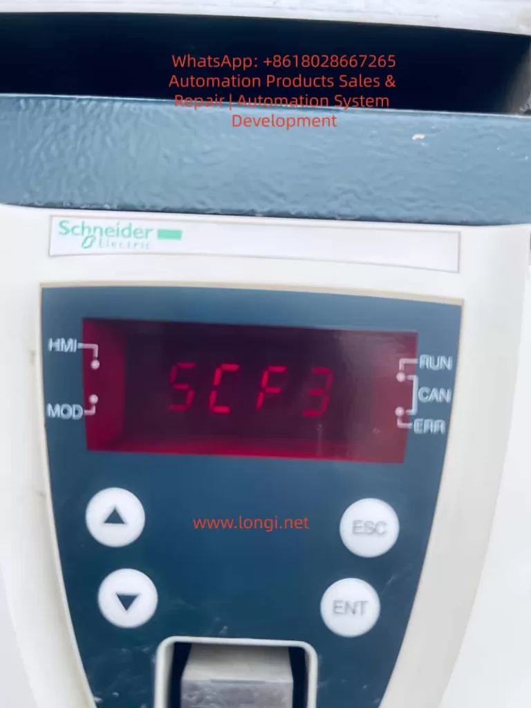
  6. ERR42 (CAN communication fault): Occurs under Mode 1 or Mode 3. Check the CAN bus wiring (CANH, CANL) for open circuit or short circuit, whether the terminal resistance matches (120Ω), and whether the communication address A2-01 and baud rate A2-00 are consistent with the controller.
  7. ERR43 (encoder fault): Occurs during tuning or operation. Check the encoder (resolver) wiring, confirm the A1-04 pole pairs, and check whether the PG card is properly inserted.
  8. ERR44 (excessive speed deviation): The deviation between the actual motor speed and the command speed exceeds the F9-14 set value and lasts longer than F9-15. Common causes include motor blockage, encoder fault, inaccurate motor parameters, and too low torque upper limit F2-10 setting.

VII. Daily Maintenance and Replacement of Vulnerable Parts

Section 2.7 of the manual provides detailed requirements for maintenance and upkeep. For Donghua Machinery users, the following regular maintenance plan is recommended:

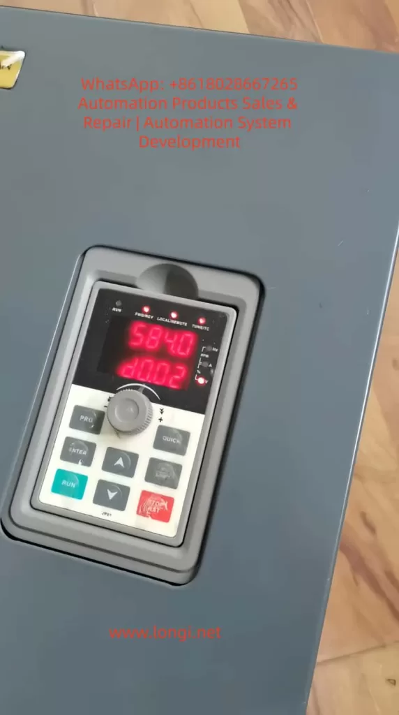
  • Daily inspection: Check whether the motor operation sound is abnormal, whether the vibration increases, whether the cooling fan runs normally, and whether the current and voltage displayed on the drive panel are within the normal range.
  • Quarterly cleaning: Use a vacuum cleaner or compressed air (dry, low pressure) to clean the dust accumulated on the drive air inlet, heat sink, and fan. For workshops with high dust levels, this should be shortened to once a month.
  • Fan replacement every two years: The manual indicates that the fan life is 2~3 years. When the fan makes abnormal noise or the speed decreases, it should be replaced immediately.
  • Electrolytic capacitor inspection every four years: The life is 4~5 years. Check for electrolyte leakage and whether the safety valve is raised. If necessary, measure the electrostatic capacitance and insulation resistance.
  • Long-term storage: If the drive is stored for more than 2 years, it must be powered on once. The power-on time should be at least 5 hours, and the voltage should be slowly increased to the rated value using a voltage regulator to restore the performance of the electrolytic capacitors.

VIII. Summary

The CM-SVC servo drive is a powerful drive product dedicated to servo oil pump control for injection molding machines. This article provides an engineering interpretation of the key content in the manual, combining the actual application scenarios of Donghua Machinery injection molding machines, from mechanical installation, electrical wiring, parameter debugging, fault handling, to daily maintenance.

The key to mastering this user guide lies in understanding three aspects: first, motor parameter tuning is the foundation and must be accurately performed; second, oil pressure PID adjustment is the soul and needs to be optimized in segments based on the process actions; third, fault codes are clues and should be judged in combination with the manual flowchart and actual measurement data on site.

It is hoped that this article can help field engineers reduce debugging time, lower fault rates, extend equipment life, and enable the CM-SVC servo drive to deliver optimal performance on Donghua Machinery’s injection molding machines.

Posted on

In-depth Analysis and Solution Guide for U-phase Current Transformer Zero Offset (CT1) Fault in Lingshida LSD-B7000 Series Inverters

I. Introduction

In industrial automation production lines, inverters serve as the core equipment for motor driving, and the accuracy of their current sampling systems directly determines the stability of motor control. The Lingshida LSD-B7000 series inverters, known for their high cost-effectiveness and reliable vector control performance, are widely applied in load scenarios such as fans, pumps, conveyor belts, and injection molding machines. However, during long-term operation, the U-phase current transformer zero offset (Fault Code 18, displaying “C”, “T”, “1”) is one of the high-frequency faults in this series of inverters. This fault can lead to abnormal current sampling values, triggering overcurrent protection shutdowns, and even causing motor damage due to misjudgment of current, seriously affecting production efficiency.

This article combines the hardware architecture, control principles, and on-site maintenance experience of the LSD-B7000 series to systematically analyze solutions for the CT1 fault from four dimensions: the nature of the fault, diagnostic procedures, solution strategies, and case studies, providing maintenance personnel with a practical technical guide.

CT1 fault of the B7000

II. The Nature and Causes of CT1 Faults

1. The Role of Current Transformers (CTs) and the Definition of Zero Offset

Current transformers are key components for current sampling in inverters. Their core function is to convert the large current in the motor windings (primary side, e.g., 0-100A) into a small current (secondary side, e.g., 0-5A) or voltage signal (e.g., 0-10V) at a fixed ratio for the main control chip (DSP/MCU) to calculate motor current, torque, and power.

Zero offset refers to the phenomenon where the secondary side output is not zero when there is no current on the primary side. For the LSD-B7000 series, a zero offset in the U-phase CT (CT1) can cause the control circuit to misjudge the motor current. When the sampled value exceeds the threshold (usually 5%-10% of the rated current), it triggers the “CT1” fault (Code 18), forcing a shutdown.

2. Main Causes of Zero Offset

The root causes of CT1 faults can be classified into three categories: hardware defects, software misconfigurations, and external interference, as detailed below:

Hardware Defects:

  • CT Damage: Residual magnetism in the iron core (due to long-term energization without demagnetization), winding short circuits/open circuits (due to worn insulation or overloading), or incorrect ratio (due to selecting the wrong model during replacement).
  • Wiring Issues: Loose primary/secondary side connections, oxidation (increasing contact resistance), or incorrect phase sequence (U/V/W reversed).
  • Sampling Circuit Faults: Operational amplifier offset (e.g., OP07 with an offset voltage exceeding 75μV), changes in sampling resistor values (e.g., a 0.1Ω resistor increasing to 0.15Ω), or leakage in filter capacitors (causing signal drift).

Software Misconfigurations:

  • Incorrect current ratio parameters (e.g., CT ratio of 100/5, but Pr012 set to 10 instead of 20).
  • Unupdated zero offset calibration parameters (due to long-term operation, CT characteristics change, requiring recalibration).
  • Improper settings for the fault auto-reset parameter (Pr137) (although CT1 belongs to codes 14-30 and cannot be auto-reset, misconfiguration may mask the fault).

External Interference:

  • Power supply fluctuations (three-phase voltage imbalance exceeding 5%).
  • Electromagnetic interference (power and signal lines not separated, shielding not grounded).
  • Load abnormalities (motor stalling or overloading causing CT iron core saturation).
LSD-B7400-4K-LD

III. Precise Diagnostic Procedures for CT1 Faults

The digital operator (LSD-B) of the LSD-B7000 series provides comprehensive fault diagnosis functions. Combined with hardware testing tools (multimeter, oscilloscope, megohmmeter), faults can be located using the following steps:

Step 1: Confirm Fault Code and Display Content

Operation: Press the DSPL key on the operator to switch to the fault display mode and observe the screen:

  • If “C”, “T”, “1” flash alternately or Code “18” is displayed directly, the CT1 fault is confirmed.
  • If other codes are displayed (e.g., “O”, “H”, “2” for overheating faults), chain faults must be excluded first.
    Note: Fault codes are latching and must be reset by pressing the STOP/RESET key before they can be cleared. Before resetting, record the operating status at the time of the fault (e.g., frequency, current, load).

Step 2: Hardware Wiring and CT Inspection

(1) Wiring Inspection

Safety Operation: Disconnect the inverter’s input power (R/S/T), wait 5 minutes (for the DC bus capacitors to discharge), and use a multimeter to measure the DC bus voltage (between P/N) to ensure it is 0V before opening the housing.
Inspection Content:

  • CT1 Primary Side (connected to motor U-phase) wiring: Check for loose terminals, broken wires, or damaged insulation.
  • CT1 Secondary Side (connected to the sampling circuit) wiring: Check for confusion with V/W phase wiring (incorrect phase sequence causes zero offset) and oxidation of terminals (polish with sandpaper and re-crimp).
  • Grounding Check: Ensure the CT housing is reliably connected to the inverter’s grounding terminal (PE) (grounding resistance must be less than 4Ω).

(2) CT Inspection

Resistance Measurement: Use a multimeter to measure the primary side resistance (normal range: 0.1-0.5Ω, e.g., about 0.2Ω for a 100/5 CT) and the secondary side resistance (normal range: 5-20Ω, e.g., about 10Ω for a 100/5 CT). If the resistance is ∞ (open circuit) or 0Ω (short circuit), the CT is damaged.
Insulation Measurement: Use a megohmmeter (500V) to measure the insulation resistance between the primary and secondary sides, between the primary side and housing, and between the secondary side and housing (normal should be greater than 10MΩ). If the insulation resistance is less than 1MΩ, the CT insulation has failed.
Residual Magnetism Detection: Use an oscilloscope to measure the CT secondary side output (with no current). If a continuous induced voltage (e.g., above 0.1V) is present, the iron core has residual magnetism and requires demagnetization using a demagnetizer.

Step 3: Sampling Circuit Inspection

The current sampling circuit of the LSD-B7000 series is usually located near the main control board, marked as “CT1”, “U-phase Sampling”, or “Current Detection”. The inspection steps are as follows:

Locate the Circuit

Find the CT1 secondary side connection terminals and follow the wires to locate the sampling resistor (usually a 0.1Ω/5W metal film resistor) and operational amplifier (e.g., OP07, LM358).

Signal Measurement

  • No-load Condition (motor stopped): Use an oscilloscope to measure the voltage across the sampling resistor (normal should be close to 0V). If the voltage exceeds 0.05V, a zero offset is present.
  • Measure the input voltage of the operational amplifier (non-inverting and inverting terminals): normal should be close to 0V. If the input voltage is abnormal, check the feedback resistor (e.g., Rf = 10kΩ) for value changes (measure resistance with a multimeter, replace if the error exceeds ±1%).
  • Measure the output voltage of the operational amplifier: normal should be close to 0V. If the output voltage is continuously high (e.g., above 1V), the operational amplifier is offset and requires replacement (the typical offset voltage of OP07 is 10μV, with a maximum of 75μV).

Component Inspection

  • Sampling Resistor: If the resistance value changes (e.g., from 0.1Ω to 0.12Ω), it will increase the sampling voltage and requires replacement with a resistor of the same specification.
  • Filter Capacitor: If the capacitor leaks (measure capacitance with a capacitor meter or insulation resistance with a multimeter), it will cause signal drift and requires replacement (e.g., a 10μF/25V electrolytic capacitor).

Step 4: Software Parameter and External Factor Inspection

Parameter Inspection

  • Enter the parameter mode (press the PROG key), select Pr012 (current transformer ratio), and confirm it matches the CT nameplate (e.g., for a CT of 150/5, Pr012 should be set to 30).
  • Select Pr050 (U-phase zero offset calibration) and check the current value (normal should be 0.00A or 0.00V). If the value is abnormal (e.g., 0.1A), recalibration is required.
  • Check Pr137 (fault auto-reset count): although CT1 belongs to codes 14-30 and cannot be auto-reset, confirm it is not misconfigured to “0” (no auto-reset for any faults).

External Factor Inspection

  • Power Supply Inspection: Use an oscilloscope to measure the input power waveform (three-phase 380V). If there are phase losses or harmonics (waveform distortion rate exceeding 10%), install an input filter.
  • Load Inspection: Use a clamp-on ammeter to measure the actual motor current and compare it with the inverter’s displayed current (error should be less than 5%). If the actual current is normal but the inverter’s display is abnormal, the sampling circuit is faulty.
  • Interference Inspection: Check if signal lines are shielded (shielding must be grounded at one end), the distance between power and signal lines is greater than 20cm, and the inverter is installed in a well-ventilated environment (temperature below 40°C).

IV. Targeted Solution Strategies for CT1 Faults

1. Hardware Fault Repair

Wiring Issues: Re-crimp loose terminals (use a torque screwdriver to tighten to 0.5N·m), polish oxidized contacts (with sandpaper), and replace damaged wires (use copper wires of the same specification with a cross-sectional area not less than the original).
CT Damage: Replace with a CT of the same model and ratio (note the installation direction: primary side connected to the motor, secondary side connected to the sampling circuit). Ensure the CT is installed more than 5cm away from the motor connection terminals to avoid vibration-induced insulation wear.
Sampling Circuit Faults:

  • Operational Amplifier Offset: Replace with the same model operational amplifier (e.g., replace OP07 with OP07D for lower offset).
  • Resistor Value Change: Replace with a metal film resistor (precision ±1%, power rating not less than the original).
  • Capacitor Leakage: Replace with an electrolytic capacitor (voltage rating not lower than the original, capacitance consistent).

2. Software Parameter Adjustment

Zero Offset Calibration:

  • Step 1: Ensure the motor is stopped (no load) and press the PROG key to enter the parameter mode.
  • Step 2: Use the up/down keys to select Pr050 (U-phase zero offset) and press the ENTER key to enter calibration mode.
  • Step 3: The screen displays the current zero offset value (e.g., 0.05A). Use the up/down keys to adjust it to 0.00A.
  • Step 4: Press the ENTER key to save and exit calibration mode (press the STOP/RESET key to return to operation mode).

Parameter Restoration: If parameters are混乱 (e.g., Pr012 set incorrectly), press PROG+DSPL keys to restore factory settings (note to back up important parameters such as motor rated power and pole pairs) and reconfigure motor parameters (Pr001-Pr005) and current parameters (Pr012).

3. External Environment Improvement

Grounding Optimization: Connect the inverter’s grounding terminal to the factory grounding busbar (grounding resistance less than 4Ω) and ground the motor housing separately (avoid common grounding interference).
Interference Suppression:

  • Power Side: Install an EMI filter (e.g., Schaffner FN2010) to suppress harmonics.
  • Output Side: Install a dv/dt filter (e.g., Siemens SINOFILTER) to reduce electromagnetic interference on the motor side.
  • Signal Lines: Use shielded twisted-pair cables (shielding connected to the inverter end) and separate them from power lines (distance greater than 20cm).
    Load Adjustment: If the motor is overloaded (actual current exceeds 1.2 times the rated current), reduce the load or replace with a higher-power motor. If stalling occurs, check the mechanical parts (e.g., bearings, conveyor belts) for jamming.

V. Typical Case Studies

Case 1: CT1 Fault Caused by Wiring Oxidation

Fault Phenomenon: An LSD-B7000-15kW inverter used for a fan suddenly stopped during operation, displaying a CT1 fault (Code 18).
Diagnostic Process:

  • After resetting, the inverter restarted but faulted again after 10 minutes.
  • Opened the housing and inspected the CT1 secondary side connection terminals, finding a black oxide film on the copper pieces with a contact resistance of 0.3Ω (normal should be less than 0.1Ω).
  • Polished the oxide film with sandpaper and re-crimped the terminals (torque 0.5N·m), reducing the contact resistance to 0.05Ω.
  • Tested operation for 24 hours, and the fault did not reoccur.
    Cause: Long-term operation in a humid environment (85%) caused oxidation of the connection terminals, leading to poor contact and signal drift on the secondary side, triggering the zero offset fault.

Case 2: Zero Offset Fault Caused by CT Residual Magnetism

Fault Phenomenon: An LSD-B7000-22kW inverter used for a water pump frequently displayed CT1 faults and could operate briefly after resetting.
Diagnostic Process:

  • Checked CT1 resistance: primary side 0.2Ω (normal), secondary side 10Ω (normal).
  • Insulation resistance: 15MΩ between primary and secondary sides (normal).
  • With no load, used an oscilloscope to measure the CT1 secondary side output: a continuous voltage of 0.2V (normal should be close to 0V), indicating residual magnetism in the iron core.
  • Demagnetized the CT iron core using a demagnetizer (operation: bring the demagnetizer close to the iron core and slowly move it away, repeating 3 times).
  • Recalibrated the zero offset (Pr050 = 0.00A), and test operation was normal.
    Cause: Frequent starting and stopping of the water pump motor (20 times per day) prevented complete demagnetization of the CT iron core, causing a residual magnetism-induced voltage on the secondary side and triggering the zero offset fault.

Case 3: Fault Caused by Sampling Resistor Value Change

Fault Phenomenon: An LSD-B7000-7.5kW inverter used for a conveyor belt displayed a CT1 fault, but the actual motor current (measured with a clamp-on ammeter) was 10A (rated current 15A), while the inverter displayed 12A.
Diagnostic Process:

  • Checked CT1: resistance and insulation were normal.
  • Inspected the sampling circuit: the sampling resistor (0.1Ω) actually measured 0.15Ω (a 50% increase).
  • Replaced the sampling resistor with a 0.1Ω/5W metal film resistor, reducing the sampling voltage from 0.15V to 0.1V (corresponding to 10A).
  • Recalibrated the zero offset (Pr050 = 0.00A), and test operation was normal.
    Cause: The sampling resistor, subjected to long-term high current (10A), heated up and increased in resistance, raising the sampling voltage and triggering the zero offset fault.

VI. Preventive Measures and Maintenance Recommendations

1. Regular Maintenance Plan

  • Monthly: Check for loose or oxidized connection terminals and clean inverter dust (use compressed air for blowing).
  • Every 3 months: Measure CT resistance and insulation resistance, and calibrate zero offset parameters (Pr050-Pr052).
  • Every 6 months: Inspect operational amplifiers, resistors, and capacitors in the sampling circuit and replace aging components.
  • Annually: Demagnetize the CT using a demagnetizer and check grounding resistance (less than 4Ω).

2. Environment Optimization

  • Installation Environment: Install the inverter in a well-ventilated, dry location (temperature 0-40°C, relative humidity less than 80%) and avoid direct sunlight.
  • Heat Dissipation Improvement: Install a cooling fan (e.g., an axial fan on top of the inverter) to ensure unobstructed heat dissipation channels.
  • Interference Protection: Separate power and signal lines, use shielded cables, and install filters.

3. Parameter Management

  • Establish Parameter Backups: Regularly back up inverter parameters using the operator or a computer (via RS485 interface) to avoid loss due to misoperation.
  • Record Parameter Modifications: When modifying parameters, record the modification time, parameter number, and before/after values for traceability.
  • Fault Recording: View the historical fault record (press the DSPL key to switch to fault record mode), analyze fault frequency, and take preventive measures in advance.

VII. Conclusion

The CT1 fault (U-phase current transformer zero offset) in Lingshida LSD-B7000 series inverters is the result of a combination of hardware defects, software misconfigurations, and external interference. However, through precise diagnosis (using fault codes and hardware testing), targeted repairs (wiring/CT/sampling circuit), software calibration (zero offset parameters), and environmental improvements (grounding/interference), this fault can be effectively resolved.

Maintenance personnel need to master the working principles of current transformers, sampling circuit testing methods, and parameter adjustment procedures, while also emphasizing preventive maintenance (regular inspection of wiring, calibration of parameters, and environmental improvement) to reduce the fault occurrence rate. For high-frequency faults (e.g., wiring oxidation, CT residual magnetism), the stability of the inverter can be further enhanced by replacing high-reliability components (e.g., silver-plated connection terminals, permalloy iron core CTs) and adding demagnetization circuits.

With the development of Industry 4.0, intelligent inverters (e.g., LSD-B8000 series) already have self-calibration functions (automatic compensation for zero offset), but traditional LSD-B7000 series still require manual maintenance. The diagnostic and solution methods in this article are not only applicable to the LSD-B7000 series but can also serve as a reference for current sampling faults in other brands of inverters.

Posted on

In-depth Analysis and Solution Guide for U-phase Current Transformer Zero Offset (CT1) Fault in Lingshida LSD-B7000 Series Inverters

I. Introduction

In industrial automation production lines, inverters serve as the core equipment for motor driving, and the accuracy of their current sampling systems directly determines the stability of motor control. The Lingshida LSD-B7000 series inverters, known for their high cost-effectiveness and reliable vector control performance, are widely applied in load scenarios such as fans, pumps, conveyor belts, and injection molding machines. However, during long-term operation, the U-phase current transformer zero offset (Fault Code 18, displaying “C”, “T”, “1”) is one of the high-frequency faults in this series of inverters. This fault can lead to abnormal current sampling values, triggering overcurrent protection shutdowns, and even causing motor damage due to misjudgment of current, seriously affecting production efficiency.

This article combines the hardware architecture, control principles, and on-site maintenance experience of the LSD-B7000 series to systematically analyze solutions for the CT1 fault from four dimensions: the nature of the fault, diagnostic procedures, solution strategies, and case studies, providing maintenance personnel with a practical technical guide.

II. The Nature and Causes of CT1 Faults

1. The Role of Current Transformers (CTs) and the Definition of Zero Offset

Current transformers are key components for current sampling in inverters. Their core function is to convert the large current in the motor windings (primary side, e.g., 0-100A) into a small current (secondary side, e.g., 0-5A) or voltage signal (e.g., 0-10V) at a fixed ratio for the main control chip (DSP/MCU) to calculate motor current, torque, and power.

Zero offset refers to the phenomenon where the secondary side output is not zero when there is no current on the primary side. For the LSD-B7000 series, a zero offset in the U-phase CT (CT1) can cause the control circuit to misjudge the motor current. When the sampled value exceeds the threshold (usually 5%-10% of the rated current), it triggers the “CT1” fault (Code 18), forcing a shutdown.

2. Main Causes of Zero Offset

The root causes of CT1 faults can be classified into three categories: hardware defects, software misconfigurations, and external interference, as detailed below:

Hardware Defects:

  • CT Damage: Residual magnetism in the iron core (due to long-term energization without demagnetization), winding short circuits/open circuits (due to worn insulation or overloading), or incorrect ratio (due to selecting the wrong model during replacement).
  • Wiring Issues: Loose primary/secondary side connections, oxidation (increasing contact resistance), or incorrect phase sequence (U/V/W reversed).
  • Sampling Circuit Faults: Operational amplifier offset (e.g., OP07 with an offset voltage exceeding 75μV), changes in sampling resistor values (e.g., a 0.1Ω resistor increasing to 0.15Ω), or leakage in filter capacitors (causing signal drift).

Software Misconfigurations:

  • Incorrect current ratio parameters (e.g., CT ratio of 100/5, but Pr012 set to 10 instead of 20).
  • Unupdated zero offset calibration parameters (due to long-term operation, CT characteristics change, requiring recalibration).
  • Improper settings for the fault auto-reset parameter (Pr137) (although CT1 belongs to codes 14-30 and cannot be auto-reset, misconfiguration may mask the fault).

External Interference:

  • Power supply fluctuations (three-phase voltage imbalance exceeding 5%).
  • Electromagnetic interference (power and signal lines not separated, shielding not grounded).
  • Load abnormalities (motor stalling or overloading causing CT iron core saturation).

III. Precise Diagnostic Procedures for CT1 Faults

The digital operator (LSD-B) of the LSD-B7000 series provides comprehensive fault diagnosis functions. Combined with hardware testing tools (multimeter, oscilloscope, megohmmeter), faults can be located using the following steps:

Step 1: Confirm Fault Code and Display Content

Operation: Press the DSPL key on the operator to switch to the fault display mode and observe the screen:

  • If “C”, “T”, “1” flash alternately or Code “18” is displayed directly, the CT1 fault is confirmed.
  • If other codes are displayed (e.g., “O”, “H”, “2” for overheating faults), chain faults must be excluded first.
    Note: Fault codes are latching and must be reset by pressing the STOP/RESET key before they can be cleared. Before resetting, record the operating status at the time of the fault (e.g., frequency, current, load).

Step 2: Hardware Wiring and CT Inspection

(1) Wiring Inspection

Safety Operation: Disconnect the inverter’s input power (R/S/T), wait 5 minutes (for the DC bus capacitors to discharge), and use a multimeter to measure the DC bus voltage (between P/N) to ensure it is 0V before opening the housing.
Inspection Content:

  • CT1 Primary Side (connected to motor U-phase) wiring: Check for loose terminals, broken wires, or damaged insulation.
  • CT1 Secondary Side (connected to the sampling circuit) wiring: Check for confusion with V/W phase wiring (incorrect phase sequence causes zero offset) and oxidation of terminals (polish with sandpaper and re-crimp).
  • Grounding Check: Ensure the CT housing is reliably connected to the inverter’s grounding terminal (PE) (grounding resistance must be less than 4Ω).

(2) CT Inspection

Resistance Measurement: Use a multimeter to measure the primary side resistance (normal range: 0.1-0.5Ω, e.g., about 0.2Ω for a 100/5 CT) and the secondary side resistance (normal range: 5-20Ω, e.g., about 10Ω for a 100/5 CT). If the resistance is ∞ (open circuit) or 0Ω (short circuit), the CT is damaged.
Insulation Measurement: Use a megohmmeter (500V) to measure the insulation resistance between the primary and secondary sides, between the primary side and housing, and between the secondary side and housing (normal should be greater than 10MΩ). If the insulation resistance is less than 1MΩ, the CT insulation has failed.
Residual Magnetism Detection: Use an oscilloscope to measure the CT secondary side output (with no current). If a continuous induced voltage (e.g., above 0.1V) is present, the iron core has residual magnetism and requires demagnetization using a demagnetizer.

Step 3: Sampling Circuit Inspection

The current sampling circuit of the LSD-B7000 series is usually located near the main control board, marked as “CT1”, “U-phase Sampling”, or “Current Detection”. The inspection steps are as follows:

Locate the Circuit

Find the CT1 secondary side connection terminals and follow the wires to locate the sampling resistor (usually a 0.1Ω/5W metal film resistor) and operational amplifier (e.g., OP07, LM358).

Signal Measurement

  • No-load Condition (motor stopped): Use an oscilloscope to measure the voltage across the sampling resistor (normal should be close to 0V). If the voltage exceeds 0.05V, a zero offset is present.
  • Measure the input voltage of the operational amplifier (non-inverting and inverting terminals): normal should be close to 0V. If the input voltage is abnormal, check the feedback resistor (e.g., Rf = 10kΩ) for value changes (measure resistance with a multimeter, replace if the error exceeds ±1%).
  • Measure the output voltage of the operational amplifier: normal should be close to 0V. If the output voltage is continuously high (e.g., above 1V), the operational amplifier is offset and requires replacement (the typical offset voltage of OP07 is 10μV, with a maximum of 75μV).

Component Inspection

  • Sampling Resistor: If the resistance value changes (e.g., from 0.1Ω to 0.12Ω), it will increase the sampling voltage and requires replacement with a resistor of the same specification.
  • Filter Capacitor: If the capacitor leaks (measure capacitance with a capacitor meter or insulation resistance with a multimeter), it will cause signal drift and requires replacement (e.g., a 10μF/25V electrolytic capacitor).

Step 4: Software Parameter and External Factor Inspection

Parameter Inspection

  • Enter the parameter mode (press the PROG key), select Pr012 (current transformer ratio), and confirm it matches the CT nameplate (e.g., for a CT of 150/5, Pr012 should be set to 30).
  • Select Pr050 (U-phase zero offset calibration) and check the current value (normal should be 0.00A or 0.00V). If the value is abnormal (e.g., 0.1A), recalibration is required.
  • Check Pr137 (fault auto-reset count): although CT1 belongs to codes 14-30 and cannot be auto-reset, confirm it is not misconfigured to “0” (no auto-reset for any faults).

External Factor Inspection

  • Power Supply Inspection: Use an oscilloscope to measure the input power waveform (three-phase 380V). If there are phase losses or harmonics (waveform distortion rate exceeding 10%), install an input filter.
  • Load Inspection: Use a clamp-on ammeter to measure the actual motor current and compare it with the inverter’s displayed current (error should be less than 5%). If the actual current is normal but the inverter’s display is abnormal, the sampling circuit is faulty.
  • Interference Inspection: Check if signal lines are shielded (shielding must be grounded at one end), the distance between power and signal lines is greater than 20cm, and the inverter is installed in a well-ventilated environment (temperature below 40°C).

IV. Targeted Solution Strategies for CT1 Faults

1. Hardware Fault Repair

Wiring Issues: Re-crimp loose terminals (use a torque screwdriver to tighten to 0.5N·m), polish oxidized contacts (with sandpaper), and replace damaged wires (use copper wires of the same specification with a cross-sectional area not less than the original).
CT Damage: Replace with a CT of the same model and ratio (note the installation direction: primary side connected to the motor, secondary side connected to the sampling circuit). Ensure the CT is installed more than 5cm away from the motor connection terminals to avoid vibration-induced insulation wear.
Sampling Circuit Faults:

  • Operational Amplifier Offset: Replace with the same model operational amplifier (e.g., replace OP07 with OP07D for lower offset).
  • Resistor Value Change: Replace with a metal film resistor (precision ±1%, power rating not less than the original).
  • Capacitor Leakage: Replace with an electrolytic capacitor (voltage rating not lower than the original, capacitance consistent).

2. Software Parameter Adjustment

Zero Offset Calibration:

  • Step 1: Ensure the motor is stopped (no load) and press the PROG key to enter the parameter mode.
  • Step 2: Use the up/down keys to select Pr050 (U-phase zero offset) and press the ENTER key to enter calibration mode.
  • Step 3: The screen displays the current zero offset value (e.g., 0.05A). Use the up/down keys to adjust it to 0.00A.
  • Step 4: Press the ENTER key to save and exit calibration mode (press the STOP/RESET key to return to operation mode).

Parameter Restoration: If parameters are混乱 (e.g., Pr012 set incorrectly), press PROG+DSPL keys to restore factory settings (note to back up important parameters such as motor rated power and pole pairs) and reconfigure motor parameters (Pr001-Pr005) and current parameters (Pr012).

3. External Environment Improvement

Grounding Optimization: Connect the inverter’s grounding terminal to the factory grounding busbar (grounding resistance less than 4Ω) and ground the motor housing separately (avoid common grounding interference).
Interference Suppression:

  • Power Side: Install an EMI filter (e.g., Schaffner FN2010) to suppress harmonics.
  • Output Side: Install a dv/dt filter (e.g., Siemens SINOFILTER) to reduce electromagnetic interference on the motor side.
  • Signal Lines: Use shielded twisted-pair cables (shielding connected to the inverter end) and separate them from power lines (distance greater than 20cm).
    Load Adjustment: If the motor is overloaded (actual current exceeds 1.2 times the rated current), reduce the load or replace with a higher-power motor. If stalling occurs, check the mechanical parts (e.g., bearings, conveyor belts) for jamming.

V. Typical Case Studies

Case 1: CT1 Fault Caused by Wiring Oxidation

Fault Phenomenon: An LSD-B7000-15kW inverter used for a fan suddenly stopped during operation, displaying a CT1 fault (Code 18).
Diagnostic Process:

  • After resetting, the inverter restarted but faulted again after 10 minutes.
  • Opened the housing and inspected the CT1 secondary side connection terminals, finding a black oxide film on the copper pieces with a contact resistance of 0.3Ω (normal should be less than 0.1Ω).
  • Polished the oxide film with sandpaper and re-crimped the terminals (torque 0.5N·m), reducing the contact resistance to 0.05Ω.
  • Tested operation for 24 hours, and the fault did not reoccur.
    Cause: Long-term operation in a humid environment (85%) caused oxidation of the connection terminals, leading to poor contact and signal drift on the secondary side, triggering the zero offset fault.

Case 2: Zero Offset Fault Caused by CT Residual Magnetism

Fault Phenomenon: An LSD-B7000-22kW inverter used for a water pump frequently displayed CT1 faults and could operate briefly after resetting.
Diagnostic Process:

  • Checked CT1 resistance: primary side 0.2Ω (normal), secondary side 10Ω (normal).
  • Insulation resistance: 15MΩ between primary and secondary sides (normal).
  • With no load, used an oscilloscope to measure the CT1 secondary side output: a continuous voltage of 0.2V (normal should be close to 0V), indicating residual magnetism in the iron core.
  • Demagnetized the CT iron core using a demagnetizer (operation: bring the demagnetizer close to the iron core and slowly move it away, repeating 3 times).
  • Recalibrated the zero offset (Pr050 = 0.00A), and test operation was normal.
    Cause: Frequent starting and stopping of the water pump motor (20 times per day) prevented complete demagnetization of the CT iron core, causing a residual magnetism-induced voltage on the secondary side and triggering the zero offset fault.

Case 3: Fault Caused by Sampling Resistor Value Change

Fault Phenomenon: An LSD-B7000-7.5kW inverter used for a conveyor belt displayed a CT1 fault, but the actual motor current (measured with a clamp-on ammeter) was 10A (rated current 15A), while the inverter displayed 12A.
Diagnostic Process:

  • Checked CT1: resistance and insulation were normal.
  • Inspected the sampling circuit: the sampling resistor (0.1Ω) actually measured 0.15Ω (a 50% increase).
  • Replaced the sampling resistor with a 0.1Ω/5W metal film resistor, reducing the sampling voltage from 0.15V to 0.1V (corresponding to 10A).
  • Recalibrated the zero offset (Pr050 = 0.00A), and test operation was normal.
    Cause: The sampling resistor, subjected to long-term high current (10A), heated up and increased in resistance, raising the sampling voltage and triggering the zero offset fault.

VI. Preventive Measures and Maintenance Recommendations

1. Regular Maintenance Plan

  • Monthly: Check for loose or oxidized connection terminals and clean inverter dust (use compressed air for blowing).
  • Every 3 months: Measure CT resistance and insulation resistance, and calibrate zero offset parameters (Pr050-Pr052).
  • Every 6 months: Inspect operational amplifiers, resistors, and capacitors in the sampling circuit and replace aging components.
  • Annually: Demagnetize the CT using a demagnetizer and check grounding resistance (less than 4Ω).

2. Environment Optimization

  • Installation Environment: Install the inverter in a well-ventilated, dry location (temperature 0-40°C, relative humidity less than 80%) and avoid direct sunlight.
  • Heat Dissipation Improvement: Install a cooling fan (e.g., an axial fan on top of the inverter) to ensure unobstructed heat dissipation channels.
  • Interference Protection: Separate power and signal lines, use shielded cables, and install filters.

3. Parameter Management

  • Establish Parameter Backups: Regularly back up inverter parameters using the operator or a computer (via RS485 interface) to avoid loss due to misoperation.
  • Record Parameter Modifications: When modifying parameters, record the modification time, parameter number, and before/after values for traceability.
  • Fault Recording: View the historical fault record (press the DSPL key to switch to fault record mode), analyze fault frequency, and take preventive measures in advance.

VII. Conclusion

The CT1 fault (U-phase current transformer zero offset) in Lingshida LSD-B7000 series inverters is the result of a combination of hardware defects, software misconfigurations, and external interference. However, through precise diagnosis (using fault codes and hardware testing), targeted repairs (wiring/CT/sampling circuit), software calibration (zero offset parameters), and environmental improvements (grounding/interference), this fault can be effectively resolved.

Maintenance personnel need to master the working principles of current transformers, sampling circuit testing methods, and parameter adjustment procedures, while also emphasizing preventive maintenance (regular inspection of wiring, calibration of parameters, and environmental improvement) to reduce the fault occurrence rate. For high-frequency faults (e.g., wiring oxidation, CT residual magnetism), the stability of the inverter can be further enhanced by replacing high-reliability components (e.g., silver-plated connection terminals, permalloy iron core CTs) and adding demagnetization circuits.

With the development of Industry 4.0, intelligent inverters (e.g., LSD-B8000 series) already have self-calibration functions (automatic compensation for zero offset), but traditional LSD-B7000 series still require manual maintenance. The diagnostic and solution methods in this article are not only applicable to the LSD-B7000 series but can also serve as a reference for current sampling faults in other brands of inverters.

Posted on

SES800 Servo Drive Er.SC1 Fault: In-Depth Analysis and Resolution Guide

I. Introduction

In the field of industrial automation, servo drives serve as the core hub connecting controllers (PLCs, upper computers) and actuating motors. Their communication stability directly determines the continuous operation capability of production lines. The SES800 series servo drives, renowned for their high cost-effectiveness and precise motion control performance, are widely applied in scenarios such as machine tools, packaging machinery, textile equipment, and logistics conveyor lines. However, during long-term operation, the Er.SC1 serial port communication anomaly is one of the most frequently reported faults by users. This can range from causing equipment shutdown to triggering production accidents. This article provides a comprehensive breakdown of the Er.SC1 fault, covering its definition, root causes, resolution process, case studies, and preventive measures, offering engineers a practical troubleshooting guide.

II. The Essence of the Er.SC1 Fault: Serial Communication Link Interruption

1. Fault Code Definition

Er.SC1 is the serial port communication anomaly fault code for SES800 drives (“SC” stands for “Serial Communication”). According to the drive manual, this fault is triggered when the following situations occur:

  • The serial communication link between the drive and external devices (PLCs, upper computers, HMIs) is interrupted.
  • Communication data frame errors occur (e.g., checksum failures, baud rate mismatches).
  • Communication anomalies are detected when fault alarm parameters are enabled.
    At this point, the drive stops motor output, and the operation panel displays “Er.SC1.” The fault can only be cleared by pressing the STOP/RESET key or resolving the underlying issue to resume operation.

2. The Role of Serial Communication Systems

The serial port of the SES800 (typically an RS485 interface, with some models supporting RS232) acts as the “nerve center” for interaction with external systems, performing the following functions:

  • Instruction Transmission: Receiving control instructions from PLCs/upper computers (e.g., start, stop, speed setting, torque limiting).
  • Status Feedback: Sending drive status information to external devices (e.g., current, voltage, rotational speed, fault codes).
  • Parameter Configuration: Modifying drive parameters via the communication interface (e.g., PID gains, acceleration/deceleration times).
  • Diagnostic Debugging: Using dedicated software (e.g., SES Studio) to read fault records and monitor real-time waveforms.
    Once the communication link is interrupted, the drive cannot receive instructions or provide feedback, causing the system to enter “safe shutdown” mode and triggering Er.SC1.
SES800-4T45

III. The Four Core Causes of the Er.SC1 Fault

Based on the SES800 manual and field troubleshooting experience, the root causes of Er.SC1 can be summarized into four categories, ranked by frequency of occurrence:

1. Baud Rate/Communication Parameter Mismatch (40%)

The baud rate serves as the “speed benchmark” for serial communication. If the baud rates of the drive and external device are inconsistent, data frame synchronization errors occur—where a “1” sent by the transmitter may be misinterpreted as a “0” by the receiver, ultimately leading to communication failures.

Key Parameters:

  • P15.03: Communication baud rate selection (default value for SES800-4T45 is 9600 bps).
  • P97.00: Fault alarm enable (bit0 = serial port communication fault alarm, 1 = enabled, 0 = disabled).
  • External device parameters: Baud rate, data bits (typically 8), stop bits (typically 1), and parity bits (typically none/even parity) for PLCs/upper computers.

Case Study: A machine tool factory’s SES800 drive connected to a Siemens S7-200 PLC triggered Er.SC1 because the PLC’s baud rate was set to 115200 bps, while the drive’s P15.03 remained at the default 9600 bps. As a result, the PLC’s instructions could not be interpreted by the drive, causing the fault.

2. Serial Communication Line Faults (30%)

Line issues are among the most common “hidden faults” in industrial settings, including:

  • Loose/Oxidized Connections: Unsecured terminal block screws or oxidized interface pins (especially for outdoor equipment).
  • Line Damage/Short Circuits: Cables squeezed by machinery, gnawed by rodents, or with damaged shielding leading to signal interference.
  • Missing Terminal Resistors: RS485 buses require 120Ω terminal resistors connected in parallel at both ends (some models have built-in resistors, while others require external ones). Failure to do so can cause signal reflections.
  • Electromagnetic Interference (EMI): Communication lines running parallel to inverter or motor power lines, resulting in crosstalk.

Case Study: A packaging machinery factory’s SES800 drive used ordinary twisted-pair cables (unshielded) for communication, running parallel to inverter power lines. Field testing revealed that the RS485 signal was superimposed with high-frequency noise (amplitude up to 3V), causing data frame checksum errors and triggering Er.SC1.

3. Upper Computer/External Device Faults (20%)

If the upper computer (industrial PC, HMI) or PLC is not functioning properly, the drive cannot establish a communication link, also triggering Er.SC1. Common scenarios include:

  • The upper computer software is not launched/has crashed (e.g., operator accidentally closed the software).
  • Mismatched communication protocols between the upper computer and drive (e.g., drive uses Modbus RTU, while upper computer uses Modbus ASCII).
  • Incorrect IP address/port settings for the upper computer (for network-based communication).
  • PLC program logic errors (e.g., failure to send a “communication enable” instruction).

Case Study: A logistics conveyor line’s SES800 drive triggered Er.SC1 because the upper computer (industrial PC) automatically restarted during a system update, failing to launch the communication software. Restarting the software resolved the fault.

4. Drive Communication Module Damage (10%)

If the above causes are ruled out, consider hardware faults in the drive’s communication module:

  • Burnt RS485 chips (e.g., MAX485) due to overvoltage or electrostatic discharge.
  • Oxidized/bent pins at the serial port interface (caused by frequent plugging/unplugging).
  • Damaged capacitors/resistors in the communication circuit (e.g., failed filtering capacitors).
ER.SC1

IV. Step-by-Step Resolution Guide for the Er.SC1 Fault

The following is a standardized troubleshooting process (ranked by priority) to help engineers quickly locate the issue:

Step 1: Confirm Fault Phenomena and Context

  • Check the operation panel: Does it display “Er.SC1”? Are there any accompanying faults (e.g., overcurrent, overvoltage)?
  • Inquire with operators: Were any parameters modified before the fault occurred? Was the communication line replaced? Did the upper computer exhibit any anomalies?
  • Check equipment status: Is the motor shut down? Does the upper computer display a “communication interruption” message?

Step 2: Investigate Upper Computer/External Device Status

Objective: Confirm whether the external device is functioning properly and sending instructions to the drive.

  • Check the upper computer: Is the software launched? Does it indicate “communication normal”?
  • Check the PLC: Is the program running? Are there any “communication fault” alarms?
  • Test instruction transmission: Use the upper computer to send a “jog” instruction and observe whether the drive responds (e.g., panel displays “RUN”).

Case Study: A textile factory’s SES800 drive triggered Er.SC1 due to a virus-induced crash of the upper computer software, which went unnoticed by the operator. Restarting the software resolved the fault.

Step 3: Inspect Communication Lines

Objective: Confirm whether the lines are connected and free from interference.

Power-Off Inspection:

  • Unplug the communication line and use a multimeter to measure the A-B resistance at the drive end (normal value should be 120Ω if terminal resistors are present).
  • Check terminal blocks for loose connections or oxidized pins. Clean and retighten them with alcohol wipes.
  • Inspect the line for damage or exposed shielding (ensure the drive end is grounded).

Power-On Inspection:

  • Use a multimeter to measure the RS485 signal voltage (A-B differential voltage should be 2–5V).
  • Use an oscilloscope to measure the signal waveform (normal waveform is an inverted square wave with consistent amplitude and no noise).
  • Replace the line with a spare shielded twisted-pair cable and observe whether the fault disappears.

Case Study: A machine tool factory’s SES800 drive had loose terminal block connections due to vibration. Tightening the terminals resolved the Er.SC1 fault.

Step 4: Verify Baud Rate/Communication Parameters

Objective: Ensure parameter consistency between the drive and external device.

  • Check drive parameters:
    • Press the “MENU” key to enter parameter mode and locate “P15.03” (baud rate).
    • Record the current value (e.g., 9600) and compare it with the external device’s baud rate (e.g., PLC’s 115200).
  • Modify parameters:
    • Use the up/down keys to select the correct baud rate (e.g., 115200 corresponds to P15.03 = 4).
    • Press “ENTER” to confirm and “MENU” to exit.
    • Power cycle the drive and check whether the fault disappears.
      Note: Before modifying the baud rate, ensure the external device’s data bits, stop bits, and parity bits match those of the drive (typically 8-1-N).

Step 5: Check Fault Alarm Parameters

Objective: Confirm whether “false alarms” are occurring due to parameter settings.

  • Check the “P97.00” parameter (fault alarm enable):
    • bit0: Serial port communication fault alarm (1 = enabled, 0 = disabled).
    • If bit0 = 1 and the communication link is normal, it may be a “false alarm” (e.g., due to interference).
  • Temporary solution: Set P97.00’s bit0 to 0 (disable alarm) and observe whether the fault is still triggered (if not, the issue is interference; if yes, the link is truly interrupted).

Step 6: Advanced Troubleshooting (Tool-Assisted)

If the above steps are ineffective, use professional tools to locate the issue:

  • Serial Port Debugging Assistant: Connect to the drive’s serial port and send Modbus instructions (e.g., 0x03 to query motor current). Observe the replies:
    • No reply: Line disconnection or communication module damage.
    • Error reply (e.g., CRC error): Baud rate mismatch or line interference.
    • Correct reply: Communication is normal; the fault may stem from upper computer logic.
  • Logic Analyzer: Capture communication data packets and analyze frame structure (start bit, data bits, stop bit, parity bit) for correctness and the presence of “error frames” (e.g., incorrect frame length, checksum failures).
  • Replacement Method: Replace the original drive with a same-model drive. If the fault disappears, the original drive’s communication module is damaged; if the fault persists, the issue lies with the external device or line.

Step 7: Reset and Recovery

  • After resolving the fault, press the operation panel’s “STOP/RESET” key to reset.
  • Restart the upper computer/PLC and send an “enable” instruction.
  • Observe the drive panel: Does it display “RUN”? Are there any new faults?

V. Typical Case Studies

Case 1: Baud Rate Mismatch Causing Frequent Shutdowns

Scenario: An SES800-4T45 drive at a packaging machinery factory, connected to a Mitsubishi FX3U PLC, frequently triggered Er.SC1.
Troubleshooting:

  • Checked upper computer: PLC program running normally, no alarms.
  • Checked lines: RS485 cables securely connected, shielding grounded.
  • Reviewed parameters: Drive’s P15.03 = 9600, PLC’s baud rate = 115200.
  • Modified parameters: Changed drive’s P15.03 to 115200 (option 4).
    Result: Fault disappeared, and the equipment ran continuously for 3 months without recurrence.

Case 2: Electromagnetic Interference Causing Occasional Faults

Scenario: An SES800 drive on a logistics conveyor line triggered Er.SC1 daily at 9 AM (when inverters started).
Troubleshooting:

  • Checked lines: Communication lines ran parallel to inverter power lines (spacing < 10 cm).
  • Detected signals: Used an oscilloscope to measure RS485 signals, finding 1 kHz noise superimposed (amplitude 3V).
  • Implemented corrections: Replaced communication lines with shielded twisted-pair cables, maintained a spacing of > 30 cm from power lines, and grounded the shielding at one end.
    Result: Noise disappeared, and Er.SC1 faults ceased.

Case 3: Upper Computer Software Crash Causing Shutdowns

Scenario: An SES800 drive at a machine tool factory triggered Er.SC1 due to an upper computer (industrial PC) automatically restarting during a system update.
Troubleshooting:

  • Checked upper computer: Software failed to launch automatically (operator had not set “auto-start”).
  • Tested: Manually launched the software and sent an “enable” instruction; drive resumed normal operation.
  • Preventive measure: Set software to “auto-start” and added a “watchdog” program (automatically restarts software if it crashes).
    Result: Fault did not recur.

VI. Preventive Measures for the Er.SC1 Fault

1. Line Maintenance

  • Inspect communication lines monthly for loose terminals, line damage, and proper shielding grounding.
  • Use shielded twisted-pair cables (RS485-specific) and avoid running them parallel to power lines.
  • Install terminal resistors: If the bus length exceeds 100 meters, connect 120Ω resistors in parallel at both ends (confirm whether the model has built-in resistors).

2. Parameter Management

  • Back up current parameters before modifying communication parameters (using the operation panel or SES Studio software).
  • Maintain a “parameter ledger” to record baud rates, protocols, and upper computer addresses for each drive.
  • Prohibit unauthorized personnel from modifying critical parameters such as P15.03 and P97.00.

3. Upper Computer Management

  • Designate a dedicated operator for the upper computer to prevent accidental software shutdowns or setting changes.
  • Install antivirus software on the upper computer and update the system regularly.
  • Set a “communication timeout alarm”: If no reply is received from the drive within 10 seconds, the upper computer prompts a “communication interruption” message.

4. Electromagnetic Interference Protection

  • Keep communication lines away from interference sources such as inverters, motors, and transformers (spacing > 30 cm).
  • Ground the drive enclosure (grounding resistance < 4Ω).
  • Use isolated communication modules (e.g., USB-to-RS485 isolators) to avoid ground loop interference.

5. Regular Maintenance

  • Clean drive dust quarterly (especially at the serial port interface).
  • Test the communication module annually: Use a serial port debugging assistant to send instructions and verify correct replies.
  • Replace aging lines: If lines have been in use for over 2 years, replace them with new shielded cables.

VII. Safety Precautions

  • Power-Off Operation: Before inspecting lines or parameters, disconnect the drive’s power (both main and control power) and wait at least 10 seconds (for capacitor discharge).
  • Electrostatic Discharge (ESD) Protection: Wear an ESD wrist strap when handling communication modules to avoid damaging chips with static electricity.
  • Tool Usage: When measuring voltage with a multimeter, select the correct range (RS485 voltage is 2–5V; avoid using high-voltage ranges).
  • Professional Repairs: If the communication module is damaged, return it to the manufacturer or an authorized repair center. Do not attempt to replace chips yourself (risk of secondary faults).

VIII. Conclusion

The Er.SC1 fault serves as a “communication warning light” for SES800 servo drives, with its root causes typically stemming from parameter mismatches, line issues, or external device faults. By following a “software-first, hardware-second” troubleshooting process (upper computer → line → parameters → hardware), over 90% of faults can be resolved quickly. Prevention focuses on standardizing line installation, strict parameter management, and enhancing upper computer maintenance—measures that can reduce the occurrence of Er.SC1 by over 80%.

For engineers, mastering Er.SC1 troubleshooting methods not only enables rapid production recovery but also allows for system design optimization (e.g., adjusting line routing, upgrading shielding measures) through “fault复盘” (fault review) to improve equipment reliability. As industrial IoT (IIoT) becomes more prevalent, SES800’s communication functions will increasingly rely on networks (e.g., EtherCAT, Profinet), but serial ports will remain critical for the “last mile” of connectivity. Prioritizing basic communication stability is essential for supporting more complex smart manufacturing systems.

Appendix: Key Communication Parameters for SES800

Parameter NumberParameter NameOptions/RangeDefault Value
P15.03Communication Baud Rate0 = 9600, 1 = 19200, 2 = 38400, 3 = 57600, 4 = 1152000 (9600)
P15.04Communication Timeout0–65535 (unit: 10 ms)100 (1 s)
P97.00Fault Alarm Enablebit0 = Serial Port Comm Fault (1 = enabled)1 (enabled)
P97.01Comm Fault Action0 = Alarm without Shutdown, 1 = Alarm with Shutdown1 (shutdown)

(Note: Parameters are based on the SES800-4T45 manual and may vary slightly for different models.)

By following this guide, engineers can systematically resolve Er.SC1 faults, minimize downtime, and improve equipment operational efficiency.

Posted on

VFD Overvoltage Fault on Power-Up: Deep Analysis of DC Bus Voltage Mechanism and Fault Localization in Detection Circuits

1. Background and Typical Fault Phenomenon

In practical field maintenance, overvoltage faults in variable frequency drives (VFDs) are common. However, a very specific and misleading condition is when the drive reports an overvoltage fault immediately after power-up, before the motor even starts.

Typical symptoms include:

  • Fault code displayed: Err.07 (Overvoltage during constant speed)
  • Fault occurs immediately after power-on
  • No motor operation or command given
  • DC bus voltage reading: approximately 580V
  • Voltage value is stable and does not fluctuate

This type of fault often leads to misdiagnosis, especially when technicians assume that overvoltage must be associated with regenerative energy or deceleration.


ERR07 fault

2. DC Bus Voltage Fundamentals

A VFD operates on an AC-DC-AC conversion principle. The incoming AC voltage is rectified and filtered to form a DC bus.

The theoretical relationship is:

[
U_{dc} \approx 1.35 \times U_{ac}
]

For a standard 380V three-phase system:

  • Theoretical DC bus voltage ≈ 380 × 1.35 ≈ 513V

In real applications, considering fluctuations and ripple:

  • Normal DC bus voltage range: 500V to 540V

Therefore, under no-load and idle conditions:

  • The DC bus voltage should remain around 510V
  • It should not naturally rise to 580V or higher

3. Two-Level Overvoltage Protection Mechanism

A common misconception is that overvoltage only occurs above 700V. In reality, VFDs implement a two-tier protection strategy:

3.1 Software-Level Protection

  • Trigger range: approximately 580V to 620V
  • Purpose: early intervention to prevent hardware damage
  • Action: fault alarm and shutdown

3.2 Hardware-Level Protection

  • Trigger range: approximately above 700V
  • Purpose: protect IGBT modules and DC capacitors
  • Action: emergency shutdown or hardware protection

Thus:

  • A reading of 580V triggering a fault is technically correct
  • However, it must represent a real voltage, not a false reading

4. Logical Contradiction in Power-Up Overvoltage

In a non-operational state:

  • No motor rotation
  • No deceleration process
  • No regenerative energy feedback

There is no physical mechanism to increase DC bus voltage beyond its rectified value.

Therefore:

If a VFD reports 580V at power-up, the key question is:

Is the voltage real, or is the measurement incorrect?


 DC voltage

5. Root Cause: Voltage Detection Circuit Error

In over 90% of such cases, the issue is not actual overvoltage, but a fault in the voltage sensing circuit.

The DC bus voltage is not measured directly. Instead, it is processed through a signal chain:


5.1 High-Voltage Divider Network

The high DC voltage (~500V) is reduced using a resistor divider:

  • Typically consists of high-value resistors (hundreds of kΩ to MΩ)
  • Output is scaled down to low voltage (e.g., 0–5V)

Failure modes:

  • Resistance drift due to aging
  • Leakage caused by moisture or contamination

Result:

  • Divider ratio changes
  • Output voltage increases
  • MCU interprets voltage as higher than actual

5.2 Operational Amplifier Stage

The divided signal is conditioned using an op-amp:

  • Buffering
  • Amplification
  • Filtering

Failure modes:

  • Input offset drift
  • Power supply instability
  • Internal damage

Result:

  • Amplified signal becomes inaccurate
  • ADC receives incorrect voltage level

5.3 ADC and Reference Voltage

The conditioned signal is fed into the MCU’s ADC:

  • Requires a stable reference voltage

Failure modes:

  • Reference voltage drops
  • ADC calibration shifts

Result:

  • All measured values appear higher than actual

6. Key Differences: Real Overvoltage vs Measurement Error

FeatureReal OvervoltageDetection Error
OccurrenceDuring operationAt power-up
Voltage behaviorDynamicStable
Load dependencyYesNo
Value patternFluctuatingFixed abnormal value
Root causeEnergy feedbackCircuit drift

The described case clearly matches the detection error scenario.


7. Practical Diagnostic Procedure

Step 1: Measure Input Voltage

Check three-phase input:

  • R-S, S-T, R-T

Expected:

  • Around 380V ±10%

If input exceeds 420V, a supply issue may exist.


Step 2: Measure Actual DC Bus Voltage

Using a multimeter:

  • Measure between P+ and N-

Interpretation:

Measured ValueConclusion
~510VDetection circuit fault
~580VReal overvoltage

Step 3: Compare with Display Value

If:

  • Multimeter shows 510V
  • Display shows 584V

Conclusion:

Voltage sensing circuit is faulty


8. Component-Level Troubleshooting

8.1 Voltage Divider Resistors

  • Check resistance values after power discharge
  • Compare with nominal values

Focus:

  • High-voltage side resistors are most prone to drift

8.2 Operational Amplifier

  • Measure input and output voltages
  • Verify linear relationship

If input is correct but output is high:

  • Op-amp is defective

8.3 Reference Voltage

  • Measure ADC reference (e.g., 2.5V or 3.3V)

If reference is lower than expected:

  • ADC readings will appear higher

9. Why This Fault is Common

9.1 Thermal Stress

  • Long-term heat exposure
  • Causes resistor drift

9.2 Humidity and Contamination

  • PCB surface leakage
  • Insulation degradation

9.3 Aging

  • Component parameter drift over time
  • Solder joint degradation

10. Misdiagnosis Related to Braking Circuit

It is often assumed that overvoltage relates to braking resistor failure.

However:

  • Braking circuits only operate during deceleration
  • They are inactive at power-up

Therefore:

  • A fault occurring immediately after power-on is not related to braking components

11. Key Maintenance Conclusions

  1. A 580V alarm is normal in terms of protection logic
  2. The real issue is why voltage reaches that level without operation
  3. Always verify DC bus voltage with a multimeter
  4. Voltage divider drift is the most probable cause
  5. Do not rely solely on displayed values

12. Practical Rule of Thumb

“Overvoltage at power-up = 90% probability of sensing circuit fault”


13. Conclusion

Understanding VFD overvoltage faults requires distinguishing between actual electrical conditions and measurement inaccuracies. In cases where faults occur immediately after power-up, the focus must shift from power circuits to sensing circuits.

By following a structured diagnostic approach—verifying real voltage, analyzing signal chains, and testing components—technicians can quickly and accurately locate the fault.

Effective troubleshooting depends not on interpreting fault codes alone, but on understanding the underlying electrical principles and circuit behavior.

Posted on

In-Depth Analysis and Board-Level Repair Guide for Yaskawa SGDM Servo Drive Alarm A.7A

1. Background and Practical Significance

Yaskawa Σ-II series (SGDM) servo drives are widely used in industrial automation systems such as CNC machines, packaging equipment, printing lines, and conveyor systems. As equipment ages, alarm-related failures become increasingly common in maintenance work.

Among these, Alarm A.7A (Heatsink Overheat) is a frequent issue and is often misdiagnosed in the field.

Many engineers treat A.7A purely as a thermal problem—focusing on cooling improvements or fan replacement. However, real-world repair experience shows:

A.7A does not always indicate actual overheating—it indicates that the drive believes it is overheating.

Understanding the detection mechanism and signal chain is therefore essential for accurate troubleshooting.


Yaskawa SGDM Servo Drive Alarm A.7A

2. Official Definition and Technical Essence of A.7A

According to the Yaskawa SGDM manual:

  • A.7A indicates a heatsink overheat alarm
  • It is triggered when the drive detects that the heatsink temperature exceeds a defined threshold

However, from a circuit perspective, the system does not directly measure temperature. Instead, it relies on voltage interpretation:

Temperature → Resistance change → Voltage change → CPU decision

Thus, A.7A is fundamentally a fault or anomaly in an analog sensing circuit, not just a thermal condition.


3. Temperature Detection Circuit Principle

The SGDM servo drive uses an NTC (Negative Temperature Coefficient) thermistor-based sensing circuit. The structure typically includes:

  • NTC thermistor (mounted on the heatsink)
  • Pull-up resistor (connected to a 5V reference)
  • Operational amplifier (signal conditioning)
  • CPU ADC (analog-to-digital conversion)

Working principle:

  1. NTC resistance decreases as temperature increases
  2. Together with the pull-up resistor, it forms a voltage divider
  3. The divider outputs a voltage signal (Vtemp) proportional to temperature
  4. The signal is conditioned by an op-amp
  5. The CPU compares the voltage against a threshold

Typical voltage behavior:

  • Normal temperature: ~2V to 3V
  • Rising temperature: voltage decreases
  • Below ~1V: triggers A.7A alarm

SGDM-15ADA

4. Fault Classification of A.7A

From a maintenance standpoint, A.7A can be divided into two major categories:


4.1 Real Overheating (Physical Cause)

Common causes include:

  • Ambient temperature exceeding 55°C
  • Blocked airflow (dust accumulation or tight installation)
  • Cooling fan failure or reduced speed
  • Prolonged overload operation
  • Excessive IGBT heat generation

Typical characteristics:

  • Alarm occurs after a period of operation
  • Heatsink temperature is physically high

4.2 False Alarm (Circuit-Level Issue)

This is more critical from a repair perspective. Common causes include:

  • NTC thermistor open circuit or short circuit
  • Drifted pull-up resistor
  • Faulty operational amplifier (offset or saturation)
  • ADC sampling error
  • Poor solder joints or connector issues

Typical characteristics:

  • Alarm appears immediately after power-on
  • Heatsink temperature is normal or low

5. Board-Level Troubleshooting Using a Multimeter

5.1 NTC Thermistor Check

Measure resistance with power OFF:

  • Normal: several kΩ to tens of kΩ
  • Open circuit: infinite resistance (will trigger alarm)
  • Short circuit: near 0Ω (abnormal)

Further verification:

  • Apply heat (e.g., hot air)
  • Resistance should decrease accordingly

5.2 Voltage Divider Node Measurement (Critical)

Measure the voltage at the junction between the NTC and pull-up resistor (Vtemp):

  • Normal: 2V–3V
  • 0V: NTC short or grounding issue
  • 5V: NTC open or pull-up fault
  • <1V: interpreted as overheat

This point is the most important diagnostic node.


5.3 Pull-Up Resistor Check

Measure resistance with power OFF:

  • Typical range: 4.7kΩ to 47kΩ
  • Open or drifted values will cause incorrect voltage levels

5.4 Operational Amplifier Check

Identify the op-amp (commonly an 8-pin IC such as LM358):

  • Input pins: should match Vtemp level
  • Output pin: should vary within 0–5V range

Failure symptoms:

  • Output stuck high: false alarm
  • Output stuck low: continuous alarm
  • No response: op-amp failure

Op-amp drift is a common issue in aging SGDM drives.


5.5 Substitution Method (Fast Diagnosis)

Remove the NTC and replace it with fixed resistors:

  • 10kΩ → simulate normal temperature
  • 1kΩ → simulate high temperature
  • 500Ω → simulate extreme heat

Interpretation:

  • Alarm disappears → NTC is faulty
  • Alarm persists → downstream circuit issue

6. Recommended Troubleshooting Workflow

A structured approach significantly improves efficiency:

  1. Determine when the alarm occurs
    • Immediate → circuit issue
    • After running → thermal issue
  2. Check cooling fan
    • Rotation and supply voltage
  3. Measure NTC resistance
  4. Measure Vtemp voltage
  5. Check op-amp input/output
  6. Perform substitution test

This process typically allows fault localization within 10–15 minutes.


7. Failure Probability Distribution (Based on Field Experience)

  • Cooling fan failure: very high
  • Poor ventilation/dust: high
  • NTC failure or poor connection: medium-high
  • Op-amp drift: medium
  • Resistor drift: medium-low
  • CPU/ADC fault: low

8. Common Misdiagnoses

  1. Treating A.7A purely as a temperature issue
  2. Focusing only on cooling improvements
  3. Ignoring the analog sensing circuit
  4. Failing to distinguish real vs false alarms

These mistakes often lead to unnecessary part replacement or repeated failures.


9. Conclusion

The A.7A alarm is not simply a thermal issue but a signal chain evaluation problem. Its core characteristics are:

  • Temperature is inferred through analog voltage
  • Any fault in the sensing chain can trigger the alarm

Therefore, the key to effective repair is not just reducing temperature, but:

Precisely identifying faults within the temperature sensing circuit

By understanding the NTC-based voltage divider, measuring the critical Vtemp node, and applying substitution testing, engineers can efficiently diagnose and repair SGDM servo drives at the board level—significantly reducing downtime and maintenance costs.

Posted on

In-Depth Analysis of Schneider ATV71 Inverter SCF3 Fault: Causes, Troubleshooting, and Comprehensive Solutions

I. Introduction

In the field of industrial automation, the Schneider Electric ATV71 series inverters are widely used in motor drive applications such as fans, pumps, conveyor lines, and machine tools due to their high reliability, rich vector control functions, and flexible communication expandability. However, during long-term operation, the SCF3 (ground short circuit) fault is one of the most common causes of inverter shutdowns in ATV71. According to a 2023 fault statistics report from an inverter manufacturer, SCF3 accounts for 28% of all ATV71 faults, primarily occurring in outdoor equipment, humid environments, and multi-motor parallel systems.

The essence of the SCF3 fault is that the ground leakage current on the inverter’s output side exceeds the threshold. If not promptly addressed, it can lead to motor winding burnout, cable fires, and even electric shock accidents. This article will systematically analyze the handling logic of the SCF3 fault from the perspectives of fault principles, cause analysis, troubleshooting steps, solutions, and preventive maintenance, providing electrical maintenance personnel with a practical technical guide.

SCF3 fault of ATV71

II. Definition and Detection Principle of SCF3 Fault

1. Fault Code Meaning

According to the ATV71 inverter’s “Fault Code Table,” SCF3 corresponds to “Ground Short Circuit.” The trigger condition is that the zero-sequence current (ground leakage current) on the output side exceeds 5%-10% of the inverter’s rated current (the specific threshold varies depending on the power rating. For example, the threshold for ATV71H075N4 (0.75 kW) is 0.05 A, and for ATV71H75N4 (7.5 kW), it is 0.3 A).

2. Core Principle: Zero-Sequence Current Detection

The ATV71 monitors the vector sum of the three-phase output currents (i.e., the zero-sequence current) in real-time through built-in zero-sequence current sensors. In an ideal three-phase balanced system, the vector sum of the three-phase currents is zero. If there is a ground fault in the motor or cable, the zero-sequence current will be equal to the ground leakage current (forming a loop: motor winding → insulation layer → ground → inverter ground terminal). When the zero-sequence current exceeds the set threshold, the inverter immediately triggers the SCF3 fault and blocks the output to prevent the fault from escalating.

3. Key Concept: Ground Leakage Current

Ground leakage current refers to the tiny current between the motor winding, cable insulation layer, and the ground. Its magnitude depends on the insulation resistance (R) and the system voltage (U), as given by the formula:

I=RU

Under normal conditions, with an insulation resistance of ≥1 MΩ (for a 380 V system), the leakage current is ≤0.38 mA. When the insulation resistance drops to 0.5 MΩ, the leakage current increases to 0.76 mA. If the insulation resistance is ≤0.1 MΩ, the leakage current is ≥3.8 mA, which may trigger the SCF3 fault (since the inverter’s threshold is usually 10-50 mA).

ATV71HD11N4Z

III. Core Causes of SCF3 Fault

The causes of the SCF3 fault can be divided into external factors (motor, cable, grounding system) and internal factors (the inverter itself), with external factors accounting for more than 85% of the cases.

1. External Factors: The Most Common Sources of Faults

(1) Motor Insulation Failure (Accounting for 40%)

The motor is the primary cause of the SCF3 fault, with common reasons including:

  • Moisture Absorption: In outdoor equipment or humid environments (e.g., sewage treatment plants), the motor winding absorbs moisture, reducing the insulation resistance from 10 MΩ to below 0.1 MΩ.
  • Aging: After more than 10 years of operation, the motor’s insulation varnish cracks and peels off, causing the winding to come into contact with the housing.
  • Mechanical Damage: Bearing wear causes the rotor to sweep the stator, or foreign objects enter the motor and scratch the winding insulation layer.

Case: An ATV71H55N4 (5.5 kW) inverter-controlled motor in a textile mill triggered the SCF3 fault after 30 minutes of operation due to a workshop humidity of 85%, which reduced the winding insulation resistance to 0.2 MΩ. After drying the motor (120°C for 6 hours), the insulation resistance recovered to 8 MΩ, and the fault disappeared.

(2) Cable Faults (Accounting for 30%)

Cables are the “weak link” connecting the inverter and the motor, with common problems including:

  • Insulation Damage: Cables in drag chains are repeatedly bent (with a bending radius <10 times the diameter) or scratched by metal filings, causing the core wire to come into contact with the shielding layer/ground.
  • Loose Connectors: The connectors between the cable and the motor/inverter are not tightened properly, leading to oxidation and increased contact resistance, which generates high temperatures and damages the insulation.
  • Shielding Layer Failure: The shielding layer of the shielded cable breaks, preventing it from conducting away the leakage current and causing current accumulation.

Data: A statistical analysis by an automobile factory shows that cable damage in drag chains is the main cause of SCF3 faults (accounting for 60% of cable faults).

(3) Multi-Motor Parallel Connection (Accounting for 15%)

When n motors are connected in parallel, the total leakage current = single-motor leakage current × n. Even if the leakage current of a single motor is 0.02 A (with an insulation resistance of 19 MΩ), the total leakage current of 3 parallel motors reaches 0.06 A. If the inverter’s threshold is 0.05 A, the SCF3 fault will be triggered.

Case: An ATV71H75N4 (7.5 kW) inverter controlling 2 parallel 3 kW motors in a water pump station frequently reported the SCF3 fault due to a total leakage current of 0.08 A (0.04 A per motor), exceeding the threshold of 0.06 A. After installing an output reactor (inductance of 2 mH), the total leakage current dropped to 0.04 A, and the fault was resolved.

(4) Poor Grounding System (Accounting for 10%)

The grounding system is the “discharge path” for leakage current. If the grounding is poor, the leakage current cannot be effectively conducted away and accumulates, triggering the fault:

  • Excessive Grounding Resistance: The grounding electrode is corroded by the soil (e.g., in sandy soil), or the grounding wire is too thin (<10 mm²), resulting in a grounding resistance >4 Ω (the specification requires ≤4 Ω).
  • Grounding Loop Current: When multiple devices share a grounding system, the grounding wires form a loop current, preventing the leakage current from being properly discharged.
  • Loose Grounding Terminals: The grounding terminals of the inverter/motor are not tightened properly, or the grounding wire is broken.

2. Internal Factors: Inverter Faults (Accounting for 5%)

If external factors are ruled out, internal problems with the inverter should be considered:

  • Current Sensor Fault: Zero-point drift of the zero-sequence current sensor (e.g., an output voltage offset of 0.1 V) causes the detected leakage current to be too large.
  • Protection Circuit Malfunction: Aging of resistors/capacitors in the protection circuit leads to a reduced threshold (e.g., from 10% to 5%).
  • Output Component Damage: IGBT or rectifier bridge breakdown causes a short circuit on the output side (usually accompanied by the SCF1 fault).

IV. Systematic Troubleshooting Steps for SCF3 Fault

The troubleshooting of the SCF3 fault should follow the principle of “from simple to complex, from outside to inside” to avoid blind disassembly of equipment. The following is the standard procedure:

Step 1: Confirm the Fault Phenomenon and Record

  • Check the Display: Confirm whether “SCF3” is displayed and whether there are accompanying faults (e.g., SCF1, overcurrent).
  • Read Fault Records: Check the zero-sequence current value, operating frequency, and output current at the time of the fault through menu 1.10 Diagnostics (e.g., a zero-sequence current of 0.1 A and an operating frequency of 30 Hz indicate that the leakage current increases with frequency).
  • Review Historical Faults: If the fault occurs frequently, analyze the pattern (e.g., triggered under specific loads or environments).

Step 2: Check Motor Insulation (The Most Critical Step)

  • Tools: 500 V megohmmeter (for 380 V motors), discharge wire.
  • Operation:
    • Power off and disconnect the motor from the inverter.
    • Short-circuit the motor winding and housing with a discharge wire to release residual charges.
    • Connect the “L” terminal of the megohmmeter to the winding (U/V/W phases are measured separately) and the “E” terminal to the housing.
    • Shake the megohmmeter (120 r/min) and read the insulation resistance value.
  • Judgment Criteria:
    • ≥1 MΩ: Normal.
    • 0.5-1 MΩ: Drying required.
    • <0.5 MΩ: Insulation failure, repair required.

Step 3: Check Motor Cable

  • Visual Inspection: Check for cable damage, excessive bending (especially in drag chains), and loose connectors.
  • Insulation Measurement: Disconnect both ends of the cable and measure the insulation resistance of the core wire to ground with a megohmmeter (≥1 MΩ is normal).
  • Shielding Layer Inspection: The shielding layer of the shielded cable must be grounded at both ends (inverter side and motor side). If the shielding layer is broken, repair it with shielding tape.

Step 4: Check Multi-Motor Parallel Connection

  • Calculate Total Leakage Current: If n motors are connected in parallel, the total leakage current Itotal​=n×Iper_motor​ (Iper_motor​ is the leakage current of a single motor, which can be measured with a megohmmeter: Iper_motor​=RinsulationU​, where U=380V and Rinsulation​ is the insulation resistance of a single motor).
  • Compare with Threshold: Refer to the ATV71 manual to find the ground leakage current threshold for the corresponding power rating (e.g., 0.1 A for ATV71H15N4 (1.5 kW)).
  • Solutions: If Itotal​ > threshold, reduce the number of parallel motors or install an output reactor (refer to the recommended inductance value in the manual, e.g., 1-2 mH for a 1.5 kW inverter).

Step 5: Check Grounding System

  • Measure Grounding Resistance: Use a grounding resistance tester (e.g., Fluke 1625) to measure the grounding resistance of the inverter’s grounding terminal (≤4 Ω is normal).
  • Check Grounding Connections: Confirm that the grounding terminals of the inverter, motor, and cable shielding layer are tightened and that the grounding wire is not broken/corroded.
  • Improve Grounding: If the grounding resistance is too high:
    • Add grounding electrodes (drive 2 m deep galvanized angle steel into the ground, with a spacing of ≥5 m).
    • Use grounding resistance reducers (fill around the grounding electrodes to reduce soil resistivity).
    • Replace with a thicker grounding wire (e.g., from 10 mm² to 16 mm² copper core wire).

Step 6: Check Inverter Itself

If all the above steps are normal, contact Schneider’s after-sales service or a professional maintenance technician:

  • Detect Current Sensor: Measure the output voltage of the sensor with a multimeter (normal is 0 V ± 0.05 V). If the offset is too large, calibrate or replace the sensor.
  • Test Protection Circuit: Use a signal generator to simulate leakage current and verify whether the protection circuit operates normally.
  • Replace Faulty Components: If the sensor or protection circuit is damaged, replace it with a component of the same model (requires manufacturer authorization).

V. Solutions and Cases for SCF3 Fault

1. Solutions for Motor Insulation Problems

  • Moisture Absorption: Place the motor in a drying oven (temperature 100-150°C, adjusted according to the insulation class, with an F-class insulation ≤155°C) for 4-8 hours until the insulation resistance is ≥1 MΩ.
  • Aging/Damage: If the winding damage area is small, repair it with epoxy resin insulation varnish. If the damage is severe, rewind the winding or replace the motor (the cost is approximately 50%-70% of the motor’s price).

2. Solutions for Cable Problems

  • Damaged Cable: Replace it with a shielded cable of the same model (e.g., YJVP-0.6/1 kV), ensuring a bending radius of ≥10 times the diameter.
  • Loose Connectors: Retighten the connectors and apply conductive paste (e.g., petroleum jelly) to prevent oxidation.
  • Shielding Layer Failure: Repair the broken shielding layer with shielding tape (e.g., 3M 1205) and ensure both ends are grounded.

3. Solutions for Multi-Motor Parallel Connection

  • Reduce Parallel Number: For example, change from 3 parallel motors to 2, reducing the total leakage current by 33%.
  • Install Output Reactor: Select an reactor with an appropriate inductance (refer to Schneider’s “ATV71 Selection Manual”) and connect it in series on the inverter’s output side to limit the leakage current. For example, for an ATV71H30N4 (3 kW) inverter, the recommended reactor inductance is 1.5-2.5 mH.

4. Solutions for Grounding System

  • Re-grounding: Install grounding electrodes (galvanized angle steel 50×50×5 mm, length 2.5 m) according to GB 50169-2016 specifications and drive them into the ground. Use a 16 mm² copper core wire for the grounding wire.
  • Use Grounding Resistance Reducers: Fill around the grounding electrodes with grounding resistance reducers (e.g., bentonite-based reducers) to reduce the grounding resistance from 10 Ω to below 2 Ω.

5. Solutions for Inverter Faults

  • Current Sensor Fault: Replace it with a sensor of the same model (e.g., LEM LA-55P) and calibrate the zero point (measure the output voltage with a multimeter and adjust it to 0 V).
  • Protection Circuit Malfunction: Replace aged resistors (e.g., 10 kΩ/1 W) or capacitors (e.g., 10 μF/25 V), or contact the manufacturer to adjust the protection threshold (requires authorization).

Actual Case Summaries

  • Case 1: Motor Winding Damage
    An ATV71H30N4 (3 kW) inverter-controlled motor in a mechanical processing plant reported the SCF3 fault during operation. The insulation resistance of the U phase was measured at 0.2 MΩ. After disassembling the motor, it was found that the insulation layer of the U-phase wire was scratched by bearing fragments. After replacing the wire and performing insulation treatment, the insulation resistance recovered to 10 MΩ, and the motor operated normally.
  • Case 2: Cable Shielding Layer Breakage
    An ATV71H75N4 (7.5 kW) inverter controlling 2 parallel motors in a packaging machine frequently reported the SCF3 fault. The cable of one of the motors was found to have a broken shielding layer, with a shielding layer-to-ground insulation resistance of 0.5 MΩ. After replacing the shielded cable and grounding both ends, the fault disappeared.
  • Case 3: Inverter Sensor Fault
    An ATV71H11N4 (11 kW) inverter in a printing press occasionally reported the SCF3 fault while the motor and cable were normal. It was detected that the output voltage of the zero-sequence current sensor was offset by 0.2 V (normal is 0 V ± 0.05 V). After replacing the sensor, the fault did not recur.

VI. Preventive Maintenance and Suggestions for SCF3 Fault

1. Regular Maintenance Plan (Key!)

Develop monthly, quarterly, and annual maintenance plans to identify potential problems in advance:

  • Monthly: Check the inverter’s display for fault codes, listen for abnormal vibrations/noise from the motor, and inspect the cable for damage.
  • Quarterly: Measure the insulation resistance of the motor/cable with a megohmmeter, check for loose grounding terminals, and clean the inverter’s cooling fan (use compressed air with a pressure of ≤0.2 MPa for blowing).
  • Annual: Detect the aging of the inverter’s internal components (capacitors, resistors), calibrate the current sensor, and test the functionality of the grounding protection circuit.
  • Every Two Years: Replace the inverter’s cooling fan (a vulnerable part with a lifespan of about 2 years) and check the lubrication of the motor bearings (add lithium-based grease).

2. Environmental Control

  • Humidity: Maintain a relative humidity of ≤60% in the environment and install a dehumidifier (e.g., Gree DH40EF).
  • Temperature: Keep the inverter’s operating environment temperature between 0-40°C and avoid direct sunlight (install a protective shed).
  • Dust: Regularly clean the dust inside the inverter (once every quarter) and install a protective cover (IP54 level).
  • Vibration: Avoid installing the inverter near equipment with high vibrations (e.g., punch presses). If unavoidable, install vibration damping pads (e.g., rubber pads with a thickness of ≥10 mm).

3. Correct Installation and Parameter Settings

  • Cable Selection: Use shielded cables (model YJVP), and ensure that the shielding layer is reliably grounded at both ends (connected to the PE terminal on the inverter side and the motor housing on the motor side).
  • Grounding Installation: The grounding terminals of the inverter, motor, and cable shielding layer must be connected to the same grounding system (with a grounding resistance of ≤4 Ω).
  • Parameter Settings: Correctly input the motor’s rated parameters (menu 1.1 Motor Type, 1.2 Rated Voltage, 1.3 Rated Current, 1.4 Rated Frequency) to ensure that the inverter accurately calculates the leakage current. Do not randomly adjust the grounding protection threshold (the fault record in menu 1.10 Diagnostics can be used to view the threshold).

4. Personnel Training

  • Operators: Train them in fault identification (e.g., stop the machine immediately when “SCF3” is displayed on the display) to avoid misoperations.
  • Maintenance Personnel: Train them in the use of megohmmeters and grounding resistance testers and familiarize them with ATV71 menu operations (e.g., viewing fault records in 1.10 Diagnostics).

VII. Common Misconceptions and Precautions

1. Misconception 1: SCF3 is Only a Motor Problem

Correction: Cable damage, poor grounding, and inverter sensor faults can also cause SCF3. A comprehensive investigation is required.

2. Misconception 2: Using a Multimeter is Sufficient for Insulation Measurement

Correction: A multimeter has a low test voltage (1.5-9 V) and cannot detect minor insulation damage. A megohmmeter (500 V or 1000 V) must be used.

3. Misconception 3: Multi-Motor Parallel Connection is Not a Concern

Correction: The total leakage current is additive. Even if the leakage current of a single motor is small, the total leakage current of multiple parallel motors may exceed the threshold. The total leakage current must be calculated.

4. Misconception 4: Connecting the Grounding Terminal is Enough

Correction: Excessive grounding resistance (>4 Ω) can prevent the leakage current from being discharged. The grounding resistance must be measured and ensured to comply with the specifications.

5. Misconception 5: The Fault Can Be Reset and the Machine Can Continue to Operate

Correction: SCF3 is a serious fault that can lead to motor burnout or inverter damage. The root cause must be thoroughly investigated and resolved before resetting and restarting the machine.

VIII. Conclusion

The SCF3 fault is the most common ground short circuit fault in ATV71 inverters, with its core cause being that the ground leakage current on the output side exceeds the threshold. During troubleshooting, a logical approach of “from outside to inside” should be followed, with a focus on checking motor insulation, cables, grounding systems, and multi-motor parallel connections. The solutions should be tailored to the specific causes, such as drying the motor, replacing cables, installing reactors, and improving grounding.

The key to preventing SCF3 faults is regular maintenance and environmental control. By identifying potential problems such as insulation degradation and cable damage in advance, the downtime caused by faults can be reduced by more than 70%. For electrical maintenance personnel, mastering the troubleshooting and solutions for SCF3 can not only quickly restore production but also extend the service life of equipment (the motor’s service life can be extended by 30%, and the inverter’s service life by 20%).

It is hoped that this article will provide valuable reference for technical personnel and contribute to the stable operation of industrial automation equipment. For further technical support, contact Schneider Electric’s local service center or refer to the “ATV71 Series Inverter Maintenance Manual.”

Posted on

In-Depth Analysis of Alarm 27 in ZSMC K-Series Servos: Causes and Solutions for Bus Encoder Battery Alarms

I. Introduction

In the realm of industrial automation, the stability of servo systems is the cornerstone of machining precision and production efficiency. The ZSMC K-Series (Zhejiang Zhishan Electric Co., Ltd.), a leading domestic servo system in China, is widely deployed in CNC machine tools, robotics, packaging machinery, and textile equipment. Its core competitive advantage lies in its support for bus-type absolute encoders, enabling high-precision position control and multi-turn position memory without the need for homing sequences upon every power-up.

However, Alarm 27 (Bus Encoder Battery Alarm 1) is one of the most frequent and critical faults encountered in this series. If not addressed promptly, it can lead to production downtime, positional deviations, and even mechanical collisions. This article provides a comprehensive technical analysis of Alarm 27, covering its definition, root causes, operational impact, step-by-step troubleshooting, and preventive maintenance strategies. This guide is designed to serve as a practical reference for field engineers and maintenance personnel.

b.27 alarm

II. Technical Definition and Trigger Mechanism of Alarm 27

1. Fault Definition

According to the official ZSMC K-Series manual, Alarm 27 corresponds to “Bus Encoder Battery Alarm 1”. The specific technical parameters are:

  • Trigger Condition: The built-in battery voltage of the encoder drops below 2.5V (the critical threshold).
  • Associated Phenomenon: Loss of Multi-turn Position Information (the total count of motor rotations).
  • Drive Action: The drive enters a protection state, inhibiting motor operation. The digital panel displays “27” or a specific battery warning code.

2. Working Principle of Bus-Type Absolute Encoders

Unlike incremental encoders, bus-type absolute encoders (utilizing protocols such as RS485 or CANopen) transmit absolute position data via a serial bus to the drive. This data includes:

  • Single-turn Position: The angular position within one revolution (0–360°).
  • Multi-turn Position: The cumulative count of revolutions since power-on.

The “absolute” nature means the system knows its exact position immediately upon power-up. This capability relies entirely on a backup power source to maintain the counter in non-volatile memory (NVRAM) or specific registers during power outages.

3. Core Function of the Encoder Battery

The encoder typically uses a CR2032 lithium coin cell (nominal voltage 3.0V) for the following purposes:

  • Maintaining Multi-turn Counters: Preserving the count of total motor rotations.
  • Storing Parameters: Saving encoder-specific data (resolution, zero offset, communication baud rate).
  • Powering Static Logic: Supplying the minimal current required for the memory retention circuit.

When the voltage falls below 2.5V, the NVRAM can no longer retain data reliably. Consequently, the multi-turn count resets to zero or becomes invalid, triggering Alarm 27 to prevent the drive from operating with unknown position data.

ZSD-K1AD0-8AB

III. Deep-Dive Root Cause Analysis

While the symptom is “low battery,” the underlying causes are multifaceted. We categorize them into four dimensions: Battery Integrity, Installation/Connection, Component Compatibility, and Environmental Factors.

1. Battery-Specific Factors

  • Natural Lifecycle: A standard CR2032 battery has a lifespan of 3–5 years at 25°C. However, in high-load applications where the encoder communicates frequently via the bus, the discharge rate increases, potentially shortening lifespan to 1–2 years.
  • Quality Issues: Counterfeit or low-quality batteries often have unstable voltage outputs or lower actual capacity. For instance, a factory using generic brand batteries reported Alarm 27 triggering within 6 months of installation.
  • Incorrect Specification: Using a battery with insufficient capacity (e.g., CR2025 instead of CR2032) results in rapid voltage sag under load.

2. Installation and Connection Issues

  • Contact Resistance: Oxidation on battery terminals (copper oxide/verdigris) or loss of spring tension in the battery holder creates high contact resistance. This causes a “voltage drop” where the actual battery voltage might be 2.8V, but the drive detects only 2.3V due to resistance.
  • Polarity Reversal: Installing the battery backward (positive to negative) can cause immediate short circuits or prevent the circuit from charging/discharging correctly.
  • Loose Bus Cabling: A loose connector on the encoder bus cable (e.g., RS485 A/B lines) can cause communication timeouts. Some ZSMC drives interpret communication failures as battery faults as a fail-safe mechanism.

3. Encoder and Drive Hardware Faults

  • Encoder Internal Short Circuit: Corrosion inside the encoder battery compartment or a failed capacitor on the encoder PCB can create a parasitic drain, draining the battery in weeks rather than years.
  • Drive Detection Circuit Failure: The voltage divider resistors or ADC (Analog-to-Digital Converter) chip on the drive’s control board may fail. In this scenario, the battery is fine, but the drive “hallucinates” a low voltage.
  • Protocol Mismatch: If the encoder uses CANopen but the drive is configured for RS485 (or vice versa), the handshake fails. While this usually triggers a communication alarm (e.g., Alarm 28), it can sometimes cascade into Alarm 27 if the drive cannot read the battery status register.

4. Environmental Factors

  • High Temperature: Lithium batteries degrade rapidly above 60°C. The chemical reaction rate doubles for every 10°C increase (Arrhenius equation). In a forging workshop where ambient temperatures reach 70°C, battery life can shrink to less than 12 months.
  • High Humidity: Humidity >80% causes galvanic corrosion on battery contacts, increasing resistance and leading to intermittent voltage detection errors.
  • Electromagnetic Interference (EMI): Proximity to high-power inverters or welders can induce noise on the encoder cables. This noise can corrupt the serial data stream, causing the drive to misinterpret the battery voltage telemetry.

IV. Impact Assessment of Alarm 27

Ignoring Alarm 27 poses significant risks to production and equipment integrity:

1. Operational Impact

  • Hard Lockout: The servo cannot start. In a CNC lathe, this means the spindle cannot turn, halting the entire production line.
  • Homing Failure: After battery replacement, if the multi-turn data is lost, the machine must re-home. If the homing method (e.g., external limit switch) is misconfigured, the axis may drift or fail to find zero.
  • Position Deviation: If the operator forces the motor to run in “relative mode” without multi-turn data, the position feedback will be inaccurate. For example, a robot arm might think it has rotated 10 times when it has only rotated 5, leading to collision or scrap parts.

2. Production and Economic Impact

  • Downtime Costs: For an automotive production line, one hour of downtime can cost tens of thousands of dollars in lost output.
  • Scrap Rates: Position errors lead to out-of-tolerance parts. In precision machining (±0.01mm), a lost multi-turn count can result in 100% scrap rates for a batch.
  • Mechanical Damage: Running a servo without absolute position knowledge can cause the tool post to crash into the chuck or the robot arm to exceed soft limits, damaging gearboxes and ball screws.

3. Long-Term Equipment Health

  • Battery Leakage: If a lithium battery is discharged below 2.0V, it risks leaking electrolyte, which corrodes the encoder PCB, permanently destroying the encoder.
  • Drive Stress: Repeated power cycles while the alarm is active can stress the drive’s IGBT modules and DC bus capacitors.

V. Troubleshooting and Resolution Procedures

(一) Systematic Troubleshooting Flow

Step 1: Confirm the Alarm Code

  • Verify via the drive’s 7-segment LED display or the ZSMC Studio software that the code is specifically “27” (Bus Encoder Battery Alarm).
  • Note: Check for coupled alarms. If Alarm 28 (Communication Error) is present, address the cabling first.

Step 2: Measure Battery Voltage

  1. Disconnect main power to the drive (wait 5 minutes for capacitors to discharge).
  2. Open the encoder battery cover (usually located on the rear or side of the motor).
  3. Use a multimeter (DC Voltage mode) to measure across the battery terminals:
    • ≥ 2.8V: Battery is healthy; investigate connection or drive logic.
    • 2.5V – 2.8V: Battery is nearing end-of-life; schedule replacement.
    • < 2.5V: Battery is dead; immediate replacement required.

Step 3: Inspect Physical Connections

  • Battery Holder: Check spring tension. Clean oxidized terminals with isopropyl alcohol and a fiberglass pen.
  • Bus Cable: Unplug and re-plug the encoder cable. Ensure the shielding is grounded properly. Check for pinched wires or broken conductors.
  • Mounting: Verify the encoder coupling set screw is tight (Torque: 5–8 N·m for ZSMC K-series).

Step 4: Verify Compatibility via Software

  • Connect to ZSMC Studio (or the handheld debugger).
  • Read Encoder Information: Confirm the model matches the drive configuration (e.g., “ZSMC-E-2048-4-24V”).
  • Check Protocol Settings: Ensure Pn001 (Encoder Type) is set to “Bus Absolute Encoder” (not “Incremental” or “Sin-Cos”).

Step 5: Isolate the Faulty Component

  • Swap Test: Replace the battery. If the alarm persists, swap the encoder with a known-good spare.
    • Alarm disappears: Original encoder is faulty (internal circuit failure).
    • Alarm remains: The drive’s detection circuit is likely damaged (requires board-level repair or drive replacement).

(二) Detailed Resolution Operations

1. Replacing the Encoder Battery

Tools: Multimeter, Phillips screwdriver, CR2032 battery (Genuine ZSMC or reputable brand like Panasonic/Sony).
Procedure:

  1. Power Down: Cut main power and wait 5 minutes.
  2. Access: Remove the encoder cover. Extract the old battery (avoid touching the PCB).
  3. Install: Insert the new battery with correct polarity (+ to +).
  4. Secure: Tighten the cover.
  5. Power Up: Restore power.

Critical Note: While some encoders support hot-swapping, ZSMC K-series recommends power-off replacement to avoid bus contention. After replacement, use ZSMC Studio to perform a “Battery Learn” (Pn002 = 1) to recalibrate the drive’s voltage detection.

2. Restoring Multi-Turn Position (Homing)

Once the battery is replaced, the multi-turn count is lost. You must re-establish the mechanical zero. ZSMC K-series supports three methods:

  • Method A: External Home (Recommended)
    1. Install a proximity sensor at the mechanical zero point.
    2. Set Pn003 (Homing Mode) = 2 (External Signal).
    3. Set Pn004 (Home Input Type) = 1 (NPN Normally Open).
    4. Press the “ORIGIN” button on the keypad. The motor will creep toward the sensor, stop upon detection, and set the position to 0.
  • Method B: Z-Phase Home
    1. Use the encoder’s Z-pulse (once per revolution).
    2. Set Pn003 = 1.
    3. The drive finds the Z-pulse edge and sets it as zero. Note: This does not reset multi-turn count unless combined with a specific “Clear Multi-turn” command.
  • Method C: Software/Manual Setting
    1. Connect ZSMC Studio.
    2. Manually rotate the axis to the mechanical zero.
    3. Click “Set Current Position as Zero” in the software.
    4. For multi-turn encoders, you may need to execute a “Multi-turn Clear” function (consult the specific encoder manual, e.g., ZSMC E-series “MULTI-TURN RESET”).

3. Addressing Environmental & Connection Issues

  • Corrosion: Apply dielectric grease to battery terminals to prevent future oxidation.
  • Vibration: Use cable ties to secure the bus cable to the motor body, preventing connector fatigue.
  • Heat: Install a forced-air cooling fan (≥5 CFM) directed at the encoder, or maintain the servo cabinet temperature below 30°C using an air conditioner.
  • Humidity: Place silica gel desiccants inside the cabinet or pot the encoder connector with epoxy for IP65 protection.

VI. Case Studies

Case 1: Intermittent Alarm Due to Poor Contact

Symptom: A ZSMC-K-110ST-M06025 servo on a CNC lathe triggered Alarm 27 intermittently. Replacing the battery did not fix it.
Investigation:

  • Measured battery voltage: 2.9V (Good).
  • Inspected holder: The positive spring was flattened and oxidized.
    Resolution:
  • Bent the spring to restore tension.
  • Cleaned contacts with contact cleaner.
  • Result: Alarm cleared permanently.

Case 2: Premature Battery Failure in High Heat

Symptom: Robotic servos in a forging plant triggered Alarm 27 every 6 months (expected life: 3 years).
Investigation:

  • Ambient temp near motor: 75°C.
  • Battery voltage: 2.2V (Dead).
    Resolution:
  1. Replaced batteries.
  2. Installed aluminum heat sinks (100cm²) on the motor backs.
  3. Installed an industrial air conditioner in the cabinet (set to 25°C).
    Result: Battery life extended to 2 years.

Case 3: Encoder Internal Short Circuit

Symptom: Packaging machine servo triggered Alarm 27 immediately after battery replacement. Could not home.
Investigation:

  • ZSMC Studio read “Battery Voltage: 2.1V” despite new battery.
  • Swapped encoder: Alarm cleared.
  • Disassembled old encoder: Found corrosion on battery terminals and a shorted capacitor on the PCB (due to 85% humidity).
    Resolution:
  • Replaced encoder.
  • Installed industrial dehumidifier in the factory (humidity controlled to 60%).

VII. Preventive Maintenance & Strategy

1. Scheduled Battery Replacement

  • Standard Environment (25°C): Check voltage every 12 months. Replace if < 2.8V.
  • High Temp (>40°C): Check every 6 months.
  • High Humidity (>70%): Check every 3 months.

2. Environmental Control

  • Temperature: Maintain servo cabinet at 20–30°C.
  • Humidity: Keep relative humidity at 40–60%.
  • EMI: Use shielded twisted-pair cables for the bus. Ground the shield at the drive end only. Keep encoder cables 30cm away from power lines.

3. Component Standardization

  • Batteries: Use only CR2032 from reputable sources (Panasonic, Sony, or ZSMC OEM).
  • Encoders: Use ZSMC-approved absolute encoders (e.g., ZSMC E-series) to ensure protocol compatibility.
  • Cables: Use factory-made bus cables (e.g., ZSMC-CABLE-RS485) to avoid impedance mismatch.

4. Digital Monitoring

  • ZSMC Studio Alerts: Configure the software to trigger a “Pre-Alarm” when battery voltage drops to 2.8V, allowing maintenance during planned downtime.
  • Maintenance Logs: Record battery changes in a logbook (Date, Axis, Voltage, Technician).

VIII. Common Pitfalls & Precautions

1. Pitfall: Replacing Battery Without Homing

  • Consequence: The drive runs in relative mode, accumulating position errors.
  • FixAlways perform a homing sequence after battery replacement.

2. Pitfall: Using Non-Standard Batteries

  • Consequence: AA/AAA batteries (1.5V) cannot power the encoder circuitry (requires 3.0V+).
  • Fix: Strictly use CR2032 (3V) or the specific model recommended in the manual.

3. Pitfall: Ignoring the Bus Cable

  • Consequence: Loose cables cause “ghost” battery alarms due to data corruption.
  • Fix: Torque screws on connectors to 0.5 N·m and use thread locker if necessary.

4. Safety Precautions

  • Electrical Shock: Always discharge the drive DC bus (wait 5 mins) before touching internal components.
  • Data Loss: Some encoders lose parameters if power is removed too long. Replace batteries quickly (within 2 minutes) if the manual specifies “live replacement.”
  • Professional Repair: Do not solder on encoder PCBs unless trained; ESD can destroy the chip.

IX. Conclusion

Alarm 27 in the ZSMC K-Series servo system is a critical indicator of battery voltage depletion leading to multi-turn position loss. While the fix often seems as simple as replacing a coin cell, the root causes range from environmental stress to hardware failures.

For engineers, mastering the voltage verification processhoming procedures, and environmental control is essential. As technology evolves, battery-less absolute encoders (using supercapacitors or energy harvesting) are emerging, promising to eliminate this issue entirely. However, until then, a proactive battery maintenance strategy is the most cost-effective way to ensure servo reliability.

Final Recommendation: Integrate battery checks into your daily “Gemba Walk” or start-up checklist. The cost of a CR2032 battery is negligible compared to the cost of a crashed machine or a day of lost production.

Posted on

INFICON UL5000 Leak Detector Error 52 Analysis: Causes of Low TMP Frequency and Systematic Troubleshooting Guide

1. Introduction

In helium mass spectrometer leak detection systems, operational stability depends heavily on the coordination of the vacuum system. The INFICON UL5000, widely used in industrial and laboratory environments, is a high-precision leak detector whose performance is closely tied to the functionality of its turbomolecular pump (TMP) and backing vacuum system.

A commonly encountered alarm in field applications is:

ERROR (52): TMP frequency is too low

This fault prevents the system from entering detection mode and can disrupt production or testing processes. This article provides a structured technical analysis of this error, including system principles, root causes, and practical troubleshooting methods.


ERROR 52 fault of the UL5000

2. System Architecture and Working Principle

Understanding Error 52 requires a clear understanding of the UL5000 system architecture.

The UL5000 consists of the following key subsystems:

  1. Vacuum System
    This includes the backing pump (such as a rotary vane or dry pump) and the turbomolecular pump. The backing pump creates the initial vacuum, while the TMP generates high vacuum conditions.
  2. Detection System
    This includes the mass spectrometer, ion source, and detector, responsible for helium detection at high sensitivity.
  3. Control System
    Comprising the frequency converter, control board, and user interface, this system manages the operation of all components.
  4. Pressure Monitoring System
    Multiple pressure sensors monitor system pressure in real time to ensure safe and stable operation.

3. Critical Startup Logic of the TMP

A key misconception is that the turbomolecular pump can start under any condition. In reality, its operation depends on the pre-vacuum level.

The startup sequence of the UL5000 is as follows:

First, the backing pump starts and reduces system pressure to a rough vacuum range.
Second, once the pressure reaches a defined threshold, the control system enables the TMP.
Third, the TMP accelerates to its nominal operating speed.
Finally, the system enters stable detection mode.

If the required vacuum level is not achieved, the TMP cannot accelerate properly.


4. Technical Meaning of Error 52

Error 52 indicates that the turbomolecular pump frequency is below the required operating level.

This implies:

The TMP has not reached its nominal rotational speed.
The control system has detected an abnormal operating condition and triggered protection.

It is important to note that this error does not necessarily mean that the pump itself is damaged. It is often a system-level issue.


550-500A UL5000

5. Root Cause Analysis

Based on field experience, the causes of Error 52 can be categorized into three main groups.

5.1 Insufficient Vacuum Conditions

This is the most common cause.

If the system pressure is too high, the gas load on the TMP increases significantly, preventing it from reaching full speed.

Typical reasons include:

Degraded or malfunctioning backing pump
Vacuum leaks in the system
Loose or improperly sealed connections
Aging or damaged sealing components

Typical symptoms include slow TMP acceleration and delayed fault occurrence.


5.2 Mechanical Issues in the Turbomolecular Pump

The TMP operates at extremely high rotational speeds and requires precise mechanical balance.

Possible issues include:

Bearing seizure or increased friction
Contamination from oil vapor or moisture
Rotor imbalance or deformation

These issues are often accompanied by abnormal noise or unstable operation.


5.3 Drive System Failure

The TMP is driven by a dedicated frequency converter.

Possible faults include:

Failure of the drive module
Unstable or insufficient power supply
Control signal issues

In such cases, the TMP may not start at all, and the error may appear immediately after power-up.


6. Systematic Troubleshooting Procedure

A structured troubleshooting approach should follow a sequence from simple to complex checks.

Step 1: Check the backing pump
Ensure the pump is operating normally and achieving sufficient vacuum.

Step 2: Inspect system sealing
Verify that all connections, flanges, and seals are intact and leak-free.

Step 3: Observe TMP behavior
Determine whether the pump starts, and check for abnormal noise or vibration.

Step 4: Verify electrical connections
Inspect power supply cables and control wiring for stability and proper connection.

Step 5: Perform system reset
Power off the system, wait for a short period, and restart.


7. Typical Fault Distribution

Based on field repair data, the causes of Error 52 are typically distributed as follows:

Most cases are related to insufficient vacuum conditions
Vacuum leakage is the second most common cause
Mechanical TMP failures are less frequent
Drive system failures are relatively rare

This distribution highlights the importance of focusing on the vacuum system before replacing major components.


8. Common Misdiagnosis and Risks

Incorrect diagnosis can lead to unnecessary costs and delays.

Common mistakes include:

Assuming the TMP is faulty without verification
Replacing expensive components without checking the vacuum system
Ignoring environmental factors

A structured diagnostic approach can significantly reduce repair costs and downtime.


9. Environmental Factors

Operating conditions play a significant role in system performance.

High humidity can introduce moisture into the system, affecting TMP operation.
High temperature accelerates component aging.
Long idle periods can lead to bearing degradation or seal failure.

These factors should be considered during troubleshooting and maintenance.


10. Preventive Maintenance Recommendations

To reduce the likelihood of Error 52, regular maintenance is essential.

Recommended practices include:

Periodic inspection of the backing pump
Replacement or maintenance of seals
Keeping the system clean and dry
Avoiding TMP startup under high-pressure conditions
Running the system periodically if it is not in regular use


11. Conclusion

Error 52 on the INFICON UL5000 is a system-level issue rather than a simple component failure. It indicates that the turbomolecular pump cannot reach its required operating speed under current conditions.

In most cases, the root cause lies in insufficient vacuum or system leakage, rather than a failure of the TMP itself.

A systematic troubleshooting approach focusing on the vacuum system should always be the first step, followed by inspection of the TMP and drive system if necessary.

Posted on

High Voltage Power Supply Replacement for Sedigraph 525: SCR-15P/24 Technical Guide

Introduction

The Micromeritics Sedigraph 525 is a widely used X-ray sedimentation analyzer for particle size measurement. One of the most critical components inside this system is the high voltage power supply module, typically the SCR-15P/24.

When this module fails, the system loses its X-ray generation capability, leading to complete operational shutdown.

However, replacing this module is not straightforward. Many engineers assume that any 24V to 1500V DC high voltage module can serve as a replacement. In reality, this assumption can lead to unstable operation, incorrect measurements, or even further damage.

This article provides a comprehensive engineering guide to understanding, diagnosing, and replacing the SCR-15P/24 high voltage power supply.


The Micromeritics Sedigraph 525

What is SCR-15P/24 High Voltage Module?

The SCR-15P/24 is an industrial-grade regulated high voltage DC power supply designed for precision applications such as X-ray systems.

Key Specifications:

  • Input Voltage: 24VDC
  • Output Voltage: 0–1500VDC (adjustable)
  • Control Signal: 0–5V analog control
  • Output Polarity: Positive high voltage
  • Power Rating: Approx. 5W
  • Output Type: Regulated DC high voltage

Unlike simple DC-DC converters, this module provides controlled and stable high voltage output.


Is the Output Pulse or DC?

A common question is whether the output of SCR-15P/24 is pulse-based or continuous.

The answer:

  • Internally: High-frequency switching (PWM-based)
  • Output: Stable DC high voltage with low ripple

This means:

  • It behaves as a DC source for the system
  • It is not a pulsed HV generator
  • Ripple is minimal and controlled

This distinction is critical for X-ray applications.


X-ray high voltage power supply board repair

Why High Voltage Stability Matters in X-ray Systems

The Sedigraph 525 relies on X-ray attenuation to determine particle size distribution. The accuracy of measurement depends heavily on voltage stability.

Key Requirements:

1. Voltage Stability

  • Small fluctuations → large measurement errors
  • Must maintain constant HV output

2. Low Ripple

  • Noise affects detector readings
  • Industrial HV modules maintain <1% ripple

3. Linear Control Response

  • Output voltage must follow control signal (0–5V)
  • Required for calibration and operation

4. Electrical Isolation

  • High insulation resistance
  • Floating output for safety

Why You Cannot Use Generic 24V to 1500V Modules

Many low-cost high voltage DC-DC modules available online claim:

  • 24V input
  • 1500V output

However, these modules typically fail in real applications.

Common Issues:

No Control Interface

  • Cannot accept 0–5V control signal
  • Only fixed output or manual adjustment

High Ripple

  • Not suitable for measurement systems

No Feedback Loop

  • Output unstable under load

Unknown Specifications

  • No datasheet
  • No reliability guarantee

Conclusion:

These modules are boost converters, not regulated high voltage power supplies.


SCR-15P/24

Requirements for SCR-15P/24 Replacement

To properly replace the original module, the alternative must meet strict criteria.

Mandatory Parameters:

ParameterRequirement
Input Voltage24VDC
Output Voltage0–1500V adjustable
Control0–5V analog input
Output TypeRegulated DC
Power≥5W
PolarityPositive HV

Recommended Replacement Options

1. Original Module Repair (Best Option)

Advantages:

  • Full compatibility
  • Lowest cost
  • No modification required

Typical failures include:

  • Internal HV breakdown
  • Switching transistor damage
  • Control circuit failure

2. Industrial Equivalent Modules

Recommended brands:

  • Analog Technologies
  • XP Power / EMCO
  • AHV alternative series

Advantages:

  • Industrial-grade reliability
  • Proper control interface
  • Low ripple output

3. Custom High Voltage Module

Many manufacturers can provide:

  • 24V input
  • 0–1500V adjustable output
  • Custom control interface

Advantages:

  • Fully compatible solution
  • Lower cost than OEM

Key Engineering Considerations for Replacement

Control Signal Matching

Ensure:

  • Input control voltage range matches system
  • Linear response between control and output

Electrical Interface

Verify:

  • Pin configuration
  • Reference voltage
  • Enable/disable signals

High Voltage Layout

Pay attention to:

  • Insulation distance
  • Grounding strategy
  • Shielding

Thermal Management

High voltage modules generate heat:

  • Ensure proper cooling
  • Avoid enclosed overheating

Field Diagnosis Procedure

Follow these steps to confirm HV module failure:

Step 1: Check Input Voltage

  • Confirm 24V supply

Step 2: Check Control Signal

  • Measure 0–5V control input

Step 3: Measure HV Output

  • No output → module failure

Practical Recommendation

Instead of searching for an exact SCR-15P/24 replacement, focus on:

👉 Functional equivalence

This includes:

  • Same voltage range
  • Same control method
  • Same stability level

Conclusion

The SCR-15P/24 is not a simple DC-DC converter but a regulated high voltage power supply designed for precision X-ray systems.

Replacing it requires careful consideration of:

  • Control compatibility
  • Output stability
  • Electrical interface

Using generic high voltage modules is not recommended for real applications.


Final Summary

High voltage replacement is not about matching voltage. It is about matching system behavior.