1. Fault Overview
In Siemens SINAMICS S120 drive systems, F07453 is a position feedback-related fault. Its typical meaning is:
LR: Position actual value preprocessing error
In practical terms, this means the drive cannot correctly process the actual position feedback required by the position control loop.
This fault is not normally related to a DC bus power failure, rectifier fault, motor overload, or main power module short circuit. It is mainly associated with the encoder feedback chain, position actual value processing, and position loop encoder assignment.
SINAMICS S120 is a modular high-performance multi-axis drive system. A typical system may include a Smart Line Module, Active Line Module, Motor Module, Control Unit, Sensor Module, DRIVE-CLiQ communication network, motor encoder, external measuring system, and BOP20 operator panel. Because of this modular architecture, fault F07453 must be analyzed systematically instead of simply judging the drive as defective.
The key point of F07453 is:
The drive cannot obtain or process a valid actual position value for the position control loop.
2. Technical Meaning of F07453
In a servo drive system, the position loop normally depends on three basic values:
- Position setpoint
This is the target position from the PLC, CNC, motion controller, or internal positioning function. - Position actual value
This is the real mechanical position feedback from the motor encoder, external encoder, linear scale, rotary encoder, or other measuring system. - Position deviation
This is the difference between the position setpoint and the position actual value.
For SINAMICS S120, the encoder signal cannot always be used directly. The drive must first process the feedback signal. This preprocessing may include:
- Detecting whether the encoder exists;
- Identifying the encoder type;
- Checking encoder communication;
- Checking encoder supply voltage and signal validity;
- Reading encoder resolution;
- Processing incremental or absolute position data;
- Checking the zero pulse or reference mark;
- Checking encoder direction;
- Converting encoder data into mechanical position;
- Calculating electrical angle when required;
- Processing multiturn absolute encoder data;
- Checking the encoder data set;
- Confirming which encoder is assigned to the position loop;
- Converting the feedback into an internal actual position value.
This process is called position actual value preprocessing.
Therefore, F07453 does not simply mean “the encoder is bad”. Its more accurate meaning is:
The drive failed while converting the encoder or measuring system feedback into a valid actual position value for the position control loop.
This failure may be caused by hardware, wiring, parameter configuration, DRIVE-CLiQ topology, encoder assignment, data set mismatch, or mechanical feedback problems.
3. Why F07453 Should Not Be First Treated as a Power Module Fault
A SINAMICS S120 booksize system is usually composed of several modules:
| Module | Main Function |
|---|---|
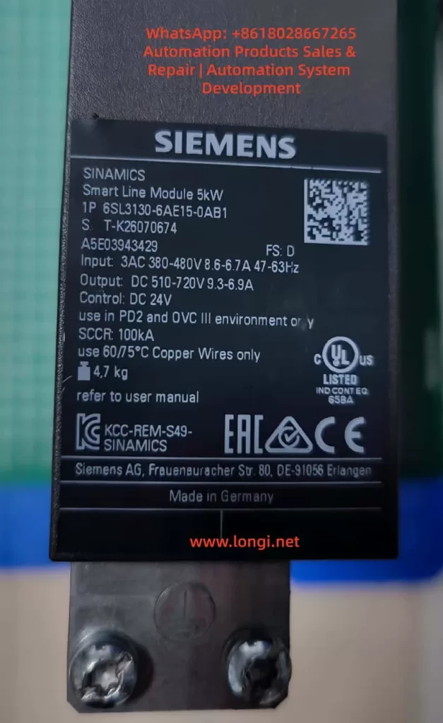
| Smart Line Module / Active Line Module | Converts three-phase AC input into DC link voltage |
| Motor Module | Converts DC link voltage into three-phase motor output |
| Control Unit | Handles axis control, communication, parameters, and system logic |
| Sensor Module | Processes external encoder or measuring system signals |
| DRIVE-CLiQ | Internal high-speed communication link |
| BOP20 | Local operation and fault display panel |
If the Smart Line Module or Active Line Module is faulty, the fault usually relates to input power, rectification, pre-charging, DC bus voltage, regenerative operation, temperature, or input phase loss.
If the Motor Module power section is faulty, the fault usually relates to overcurrent, ground fault, short circuit, IGBT failure, output phase loss, or motor insulation failure.
However, F07453 belongs to the position feedback and position actual value processing category. The main focus is not the power circuit, but whether the drive can receive and process valid feedback for the position loop.
Therefore, when troubleshooting F07453, the first priority should be:
- Encoder;
- Encoder cable;
- Encoder connector;
- Sensor Module;
- DRIVE-CLiQ communication;
- Encoder parameters;
- Position loop encoder assignment;
- Motor and encoder data sets;
- Drive Object configuration;
- Mechanical feedback system.
The Smart Line Module or main power section should only be considered after the feedback chain and parameter configuration have been checked.
4. Common Causes of F07453
4.1 Encoder Failure
The encoder is the source of the actual position value. If the encoder fails, the drive may not receive valid position feedback and may trigger F07453.
Common encoder-related problems include:
- Internal encoder circuit failure;
- Encoder power supply short circuit;
- Contaminated optical encoder disc;
- Damaged magnetic encoder ring;
- Abnormal multiturn absolute encoder data;
- EnDat, SSI, or DRIVE-CLiQ encoder communication failure;
- Weak A/B/Z incremental signals;
- Distorted Sin/Cos signals;
- Damaged encoder memory data;
- Moisture, oil, or dust inside the encoder;
- Poor contact inside the encoder connector.
If the drive reports F07453 immediately after power-on or immediately after enable, the encoder should be checked first. When the motor shaft is turned manually, the actual position value should change continuously in the engineering software. If the value does not change, jumps randomly, changes in the wrong direction, or becomes invalid, the encoder or feedback chain is highly suspicious.
4.2 Encoder Cable, Connector, or Shielding Problem
The encoder cable is one of the most common causes of F07453. Encoder signals are weak signals, especially Sin/Cos, TTL, HTL, SSI, and EnDat signals. They are sensitive to cable quality, shielding, grounding, and connector reliability.
Typical cable and connector problems include:
- Loose encoder connector;
- Bent, oxidized, or retracted connector pins;
- Oil or moisture inside the connector;
- Broken wire inside a drag chain cable;
- Damaged shield layer;
- Poor shield grounding;
- Encoder cable bundled together with motor power cable;
- Encoder cable routed near contactors, braking resistors, or other high-interference sources;
- Incorrect wiring in a custom-made encoder cable;
- Cable length exceeding the recommended limit;
- Cable mechanically crushed or stretched.
If F07453 occurs only at a certain machine position or randomly during movement, a broken wire inside the drag chain should be suspected. Static continuity measurement with a multimeter may not reveal the problem. The cable may appear normal when stationary but fail during movement.
In this case, replacing the encoder cable with a known good cable is often more effective than simple continuity testing.
4.3 Encoder Power Supply Problem
Different encoders require different supply voltages, such as 5 V, 10 V, 24 V, or 10–30 V. If the encoder supply is unstable or incorrect, the encoder cannot output valid feedback signals.
Typical problems include:
- No encoder supply voltage;
- Low encoder supply voltage;
- Excessive ripple on the encoder supply;
- Insufficient current capacity;
- Poor contact in the supply wires;
- Internal encoder short circuit pulling down the supply;
- Abnormal 0 V reference;
- Incorrect shorting between shield and signal ground;
- Damaged encoder supply output from the Sensor Module.
The encoder supply should be measured with the encoder connected, not only under no-load conditions. A no-load voltage may appear normal, but the voltage may drop significantly when the encoder is connected and operating.
4.4 Sensor Module Failure or Incorrect Configuration
In many S120 systems, encoder feedback is connected through SMC or SME Sensor Modules rather than directly through the motor. If the Sensor Module fails or is incorrectly configured, F07453 may occur.
Possible Sensor Module-related causes include:
- Faulty SMC20, SMC30, or other Sensor Module;
- Abnormal module power supply;
- Communication problem between Sensor Module and Control Unit;
- Poor connector contact;
- Encoder type incompatible with the Sensor Module;
- Changed DRIVE-CLiQ topology;
- Module replaced but not re-identified;
- Actual module type different from the configured module type;
- Wrong encoder data set assignment.
If several identical Sensor Modules are available on the machine, cross-swapping can be used to determine whether the fault follows the module.
4.5 DRIVE-CLiQ Communication or Topology Problem
DRIVE-CLiQ is the internal communication system used by SINAMICS S120 to connect the Control Unit, Motor Modules, Sensor Modules, and DRIVE-CLiQ motors. Although F07453 is not purely a communication fault, DRIVE-CLiQ problems can prevent encoder data from being correctly identified or used.
Typical DRIVE-CLiQ-related causes include:
- Loose DRIVE-CLiQ cable;
- Damaged DRIVE-CLiQ cable;
- Changed topology sequence;
- Topology mismatch after module replacement;
- Dirty or oxidized DRIVE-CLiQ connector;
- Incorrect cable used instead of a suitable DRIVE-CLiQ cable;
- Actual wiring different from the project topology;
- Control Unit unable to identify a node correctly.
The S120 system is sensitive to topology. After replacing modules or reconnecting cables, the actual DRIVE-CLiQ topology must match the project configuration.
4.6 Incorrect Position Loop Encoder Assignment
F07453 is closely related to encoder assignment in the position loop. In a S120 axis, the position feedback source may be:
- Motor encoder;
- Second encoder;
- Load-side encoder;
- Linear scale;
- Rotary encoder;
- Direct measuring system;
- Virtual encoder;
- Actual position value from a higher-level controller.
The position loop must know exactly which feedback source to use. If the position loop is assigned to a non-existing, inactive, invalid, or incorrectly configured encoder, F07453 may occur.
Typical examples include:
- The machine only has a motor encoder, but the position loop is assigned to encoder 2;
- The system uses a load-side scale, but the project still points to the motor encoder;
- The encoder data set was not created after motor replacement;
- A Drive Data Set refers to the wrong Encoder Data Set;
- Parameters copied from another axis created encoder assignment mismatch;
- Project download cleared or changed the position feedback source.
In this situation, the hardware may be completely normal, but the drive still cannot use the actual position value because the assignment is wrong.
4.7 Motor, Encoder, and Drive Parameter Mismatch
SINAMICS S120 is a highly parameterized servo system. Motor data, encoder data, power module data, mechanical transmission ratio, control mode, and topology must match each other.
Common mismatch cases include:
- Motor replaced with a different model;
- Encoder replaced with a different type;
- Substitute motor used without parameter update;
- Motor nameplate data not matching the project;
- Encoder pulse number set incorrectly;
- Absolute encoder bit number set incorrectly;
- Sin/Cos interpolation setting incorrect;
- Motor pole pair number incorrect;
- Mechanical transmission ratio incorrect;
- Encoder direction incorrect;
- Motor Data Set and Encoder Data Set not matching;
- Drive Object parameters copied from another machine.
This type of problem is common after maintenance, especially when used spare parts, repaired modules, replacement motors, or copied CF card data are involved. Two motors may look physically similar but have completely different encoder systems.
4.8 Mechanical Feedback System Problem
Although F07453 mainly points to feedback signal processing or parameter assignment, mechanical problems can also cause abnormal actual position feedback, especially when a load-side encoder or linear scale is used.
Possible mechanical causes include:
- Loose encoder coupling;
- Broken encoder shaft;
- Slipping belt;
- Excessive gearbox backlash;
- Contaminated linear scale head;
- Loose scale installation;
- Load encoder direction opposite to motor encoder direction;
- Mechanical axis jammed;
- Reference switch problem;
- Lost machine zero point;
- External measuring system shifted from its original position.
If the system uses dual encoders, such as a motor encoder for the speed loop and a load-side encoder for the position loop, checking only the motor encoder is not enough. The actual feedback source used by the position loop must be confirmed.
5. Systematic Troubleshooting Procedure
5.1 Identify the Faulty Drive Object
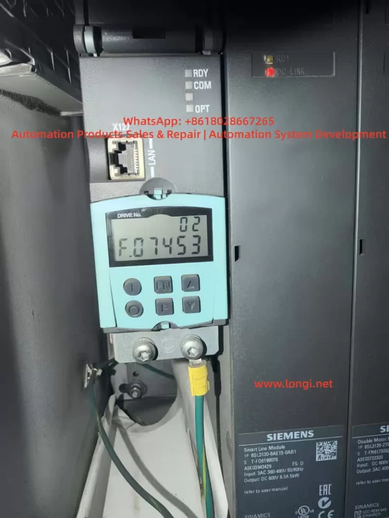
S120 is a multi-axis system. One Control Unit may manage several Drive Objects. When BOP20 displays F07453, the first step is to identify which Drive Object is reporting the fault.
The following information should be confirmed:
- Drive No.;
- Drive Object name;
- Related Motor Module channel;
- Related motor;
- Related encoder;
- Related Sensor Module;
- Whether the axis uses position control;
- Whether EPOS is used;
- Whether a second encoder or external measuring system is used.
Without identifying the correct axis, troubleshooting may focus on the wrong motor or module.
5.2 Read Fault Records and Fault Values
Fault records should be read through BOP20, STARTER, or Startdrive.
Important information includes:
- Current fault code;
- Fault value;
- Fault time;
- Faulty Drive Object;
- Associated alarms or faults;
- Whether the fault occurs at power-on, enable, running, homing, or positioning;
- Whether the fault can be reset;
- Whether it returns immediately after reset.
If F07453 appears together with encoder, DRIVE-CLiQ, encoder supply, or encoder data set alarms, those associated messages should guide the next step.
5.3 Check Encoder Connector and Cable
This is the most practical field inspection step.
Recommended checks:
- Power off and reconnect the encoder connector;
- Check the connector locking mechanism;
- Inspect pins for bending, oxidation, or retraction;
- Check the cable jacket for damage;
- Inspect drag chain sections;
- Check whether the cable is crushed or stretched;
- Confirm proper shield connection;
- Separate encoder cable from motor power cable;
- Check cabinet grounding;
- Replace with a known good encoder cable for testing.
Encoder cable problems should not be judged only by static continuity measurement. Signal quality, shielding, dynamic bending, and high-frequency integrity are equally important.
5.4 Check Encoder Supply and Signal
For traditional encoders such as incremental, Sin/Cos, SSI, or EnDat, encoder supply and signal quality should be checked.
Supply checks:
- Correct supply voltage;
- No voltage drop under load;
- Low ripple;
- Reliable 0 V reference;
- No short to ground;
- Sensor Module encoder supply output normal.
Signal checks:
- A/B signals present;
- Z pulse or reference mark present if required;
- Sin/Cos amplitude normal;
- SSI / EnDat communication stable;
- Signal changes continuously when shaft rotates;
- No spikes, missing pulses, or amplitude collapse;
- Shielding effective.
If an oscilloscope is used, grounding must be handled carefully to avoid creating a short circuit or introducing interference.
5.5 Monitor the Actual Position Value Online
Using STARTER or Startdrive to monitor the actual position value is one of the most important diagnostic methods.
When the motor shaft is manually turned under safe conditions, the actual position value should:
- Change continuously;
- Change in the correct direction;
- Not jump randomly;
- Not become invalid;
- Not disappear intermittently;
- Show normal encoder status;
- Show normal topology status.
Abnormal symptoms include:
- Position value does not change;
- Position value jumps randomly;
- Direction is reversed;
- Value suddenly resets;
- Value becomes invalid;
- Encoder cannot be detected;
- Encoder status appears and disappears;
- Fault occurs immediately when the shaft is turned.
These observations can help distinguish between encoder, cable, Sensor Module, and parameter problems.
5.6 Check Position Loop Encoder Assignment
If the encoder appears online but F07453 remains, the position loop encoder assignment must be checked.
Key points:
- Whether position control is enabled;
- Which feedback source is assigned to the position loop;
- Whether the assigned encoder actually exists;
- Whether a second encoder is configured;
- Whether an external measuring system is used;
- Whether the Encoder Data Set is valid;
- Whether Drive Data Set switching changes encoder reference;
- Whether copied parameters created encoder number mismatch;
- Whether topology changes were updated in the project.
If the position loop is assigned to the wrong encoder, the encoder may appear healthy, but the position control loop still cannot use the actual value.
5.7 Check Motor and Encoder Data Sets
If the motor, encoder, Motor Module, Control Unit, CF card, or project has been replaced or modified, the data sets must be verified carefully.
Important checks include:
| Item | Possible Problem |
|---|---|
| Motor model | Control model does not match actual motor |
| Encoder type | Feedback cannot be processed correctly |
| Encoder resolution | Position value conversion error |
| Encoder direction | Position loop instability or error |
| Mechanical ratio | Incorrect actual position scaling |
| Motor pole pair number | Incorrect electrical angle calculation |
| Encoder Data Set | Invalid or wrong data set |
| Drive Data Set | Wrong feedback source after switching |
| Topology | Actual hardware does not match project |
A module that powers up normally is not necessarily correctly configured. In S120 systems, hardware and parameters must match exactly.
5.8 Perform Cross-Swapping Tests
If identical axes or spare modules are available, cross-swapping is an efficient way to identify the fault source.
Recommended sequence:
- Swap encoder cables;
- Swap DRIVE-CLiQ cables;
- Swap Sensor Modules;
- Swap motor encoder or complete motor;
- Swap Motor Module channel;
- Consider Control Unit or CF card only at the final stage.
Judgment table:
| Swapped Part | If the Fault Follows | Likely Cause |
|---|---|---|
| Encoder cable | Yes | Cable problem |
| Motor / encoder | Yes | Encoder or motor feedback problem |
| Sensor Module | Yes | Sensor Module problem |
| Motor Module channel | Yes | Motor Module interface or channel problem |
| Parameter / CF card | Yes | Parameter or project problem |
| Same mechanical axis | Yes | Mechanical side or field wiring problem |
Parameters must be backed up before cross-swapping. Randomly exchanging Control Units, CF cards, or project files may create new topology or safety configuration problems.
6. Troubleshooting by Fault Scenario
6.1 Machine Was Working Normally, Then Suddenly Reports F07453
In this case, hardware and connection issues are more likely.
Priority checks:
- Encoder cable damage;
- Loose encoder connector;
- Encoder failure;
- Sensor Module failure;
- DRIVE-CLiQ cable problem;
- Shielding or grounding issue;
- Increased field interference.
Recommended actions:
- Check encoder connector and cable;
- Check encoder supply voltage;
- Replace encoder cable;
- Check Sensor Module;
- Monitor actual position value;
- Replace encoder or motor if necessary.
If no parameter changes were made, the probability of sudden parameter mismatch is lower.
6.2 F07453 Appears After Module Replacement
In this case, topology and parameter mismatch are more likely.
Possible causes:
- DRIVE-CLiQ topology changed;
- Replacement module is not exactly the same;
- Motor Module channel assignment changed;
- Sensor Module address or connection order changed;
- Topology was not re-identified;
- Wrong encoder data set reference;
- Wrong position loop encoder assignment.
Recommended actions:
- Check the actual module type;
- Check DRIVE-CLiQ connection sequence;
- Re-identify topology online;
- Verify Drive Object mapping;
- Check position loop encoder assignment;
- Download the correct project;
- Check encoder status for all axes.
6.3 F07453 Appears After Motor Replacement
This is often caused by encoder type mismatch or unchanged parameters.
Recommended actions:
- Compare the complete old and new motor model numbers;
- Compare encoder types;
- Compare encoder resolution;
- Check encoder connector pin assignment;
- Reconfigure motor data;
- Re-identify the DRIVE-CLiQ motor if applicable;
- Check actual position value;
- Perform encoder calibration or reference point setup if required.
Servo motors cannot be replaced only by comparing power, speed, and frame size. Encoder type and data are critical.
6.4 F07453 Appears at Power-On but Can Be Reset Later
This usually suggests temperature-related, contact-related, moisture-related, or aging problems.
Possible causes:
- Cold-state encoder fault;
- Sensor Module cold solder joint;
- Oxidized connector;
- Aging capacitor in encoder supply circuit;
- Moisture inside cabinet;
- Intermittent cable contact;
- Strong interference during power-up.
Recommended actions:
- Read the fault immediately in cold state;
- Measure encoder supply in cold state;
- Check whether the encoder is online in cold state;
- Use heat or freeze spray to locate sensitive components;
- Check cabinet moisture and oil contamination;
- Replace encoder cable;
- Check Sensor Module.
A fault that disappears after warm-up should not be ignored, because it often becomes worse over time.
6.5 F07453 Occurs Randomly During Operation
Random F07453 faults are usually related to signal quality, movement, or interference.
Priority checks:
- Drag chain encoder cable;
- Vibration at encoder connector;
- Shield connection;
- Motor power cable interference;
- Cabinet grounding;
- Sensor Module contact;
- Encoder signal amplitude;
- Cable tension at certain axis positions.
Recommended actions:
- Move the axis to different positions and gently flex the cable;
- Inspect drag chain cable sections;
- Replace encoder cable;
- Separate encoder cable from motor power cable;
- Improve shielding and grounding;
- Record the axis position when the fault occurs;
- Check whether actual position value jumps.
7. Common Misdiagnoses
7.1 Misdiagnosing the Smart Line Module
F07453 concerns position actual value processing. It is not primarily a DC bus or rectifier fault. Replacing the Smart Line Module first is usually not the correct approach.
7.2 Misdiagnosing the Motor Module Power Stage
Motor Module power stage faults usually produce overcurrent, short circuit, ground fault, or output phase faults. F07453 points more strongly to feedback and position processing.
7.3 Checking Only Motor Power Cables
Servo systems depend heavily on encoder feedback. Encoder cables, connectors, shielding, and signal quality must be checked carefully.
7.4 Checking Encoder Presence but Not Feedback Quality
An encoder may be detected but still provide unstable, incorrect, or mismatched position data. The actual position value must be monitored for continuity, direction, and stability.
7.5 Copying Parameters from a Similar Axis
A similar axis may have different encoder direction, mechanical ratio, zero point, limit direction, or safety settings. Blind parameter copying may create more faults.
7.6 Performing Factory Reset Without Backup
S120 systems contain complex motor, encoder, topology, positioning, and safety parameters. A factory reset without a full backup can make recovery much more difficult.
8. Recommended Repair Logic
A practical troubleshooting sequence for F07453 is:
- Confirm the system architecture;
- Identify the faulty Drive Object;
- Read fault records and fault values;
- Check associated encoder or DRIVE-CLiQ alarms;
- Inspect encoder connector and cable;
- Check encoder supply voltage;
- Monitor actual position value online;
- Check position loop encoder assignment;
- Verify motor and encoder data sets;
- Check DRIVE-CLiQ topology;
- Check Sensor Module;
- Perform cross-swapping tests;
- Replace encoder, motor, cable, or Sensor Module if confirmed;
- Consider Motor Module, Control Unit, or project data only after previous checks.
The key repair principle is:
Check feedback before power hardware; check cable before module; identify the correct axis before replacing parts; back up parameters before making changes.
9. Practical Diagnostic Logic
When a SINAMICS S120 system reports F07453, the fault should be classified as a position feedback processing problem, not simply as “drive failure”.
The actual position value follows this logical path:
Encoder generates position data → encoder cable transmits the signal → Sensor Module or DRIVE-CLiQ receives the signal → Control Unit identifies the encoder → parameter system assigns the encoder → position loop uses the actual value.
Any failure in this chain may trigger F07453.
If the fault appears after replacing a motor, module, Control Unit, CF card, or project download, parameter and topology mismatch should be the main focus.
If the machine has been running normally for a long time and then suddenly reports the fault, encoder, cable, connector, and Sensor Module should be checked first.
If the fault occurs randomly during movement, shielding, grounding, drag chain cable, connector vibration, and signal quality should be checked first.
If the fault occurs during homing, positioning, or enable, position loop feedback assignment, external measuring system, and mechanical reference system should be checked first.
Correct diagnosis depends on chain-based thinking, not single-part guessing.
10. Conclusion
Siemens SINAMICS S120 fault F07453 means position actual value preprocessing error. It indicates that the drive cannot correctly process the actual position feedback required by the position control loop.
This fault is usually related to:
- Encoder failure;
- Encoder cable or connector problem;
- Encoder power supply issue;
- Sensor Module fault;
- DRIVE-CLiQ topology or communication problem;
- Incorrect position loop encoder assignment;
- Motor and encoder data mismatch;
- Invalid Encoder Data Set;
- External measuring system problem;
- Mechanical feedback system abnormality.
F07453 should not be diagnosed first as a Smart Line Module failure or main power module failure. The correct troubleshooting direction is the position feedback chain.
The most important questions are:
- Which Drive Object reports the fault?
- Which encoder is used by the position loop?
- Is the encoder online and valid?
- Is the encoder cable reliable?
- Is the encoder supply stable?
- Is the Sensor Module working correctly?
- Is the DRIVE-CLiQ topology correct?
- Is the encoder assignment correct?
- Do the motor and encoder data match the actual hardware?
- Is the actual position value continuous, stable, and reasonable?
For field repair, the most effective approach is to diagnose online first, inspect encoder wiring and feedback hardware, verify parameters and topology, and then use cross-swapping to confirm the defective component.
The core idea of F07453 troubleshooting can be summarized in one sentence:
The drive is not necessarily lacking power, and the power module is not necessarily defective; the position loop is failing because it cannot obtain a valid and trustworthy actual position feedback value.