Posted on

In-Depth Analysis of Schneider ATV71 Inverter SCF3 Fault: Causes, Troubleshooting, and Comprehensive Solutions

I. Introduction

In the field of industrial automation, the Schneider Electric ATV71 series inverters are widely used in motor drive applications such as fans, pumps, conveyor lines, and machine tools due to their high reliability, rich vector control functions, and flexible communication expandability. However, during long-term operation, the SCF3 (ground short circuit) fault is one of the most common causes of inverter shutdowns in ATV71. According to a 2023 fault statistics report from an inverter manufacturer, SCF3 accounts for 28% of all ATV71 faults, primarily occurring in outdoor equipment, humid environments, and multi-motor parallel systems.

The essence of the SCF3 fault is that the ground leakage current on the inverter’s output side exceeds the threshold. If not promptly addressed, it can lead to motor winding burnout, cable fires, and even electric shock accidents. This article will systematically analyze the handling logic of the SCF3 fault from the perspectives of fault principles, cause analysis, troubleshooting steps, solutions, and preventive maintenance, providing electrical maintenance personnel with a practical technical guide.

SCF3 fault of ATV71

II. Definition and Detection Principle of SCF3 Fault

1. Fault Code Meaning

According to the ATV71 inverter’s “Fault Code Table,” SCF3 corresponds to “Ground Short Circuit.” The trigger condition is that the zero-sequence current (ground leakage current) on the output side exceeds 5%-10% of the inverter’s rated current (the specific threshold varies depending on the power rating. For example, the threshold for ATV71H075N4 (0.75 kW) is 0.05 A, and for ATV71H75N4 (7.5 kW), it is 0.3 A).

2. Core Principle: Zero-Sequence Current Detection

The ATV71 monitors the vector sum of the three-phase output currents (i.e., the zero-sequence current) in real-time through built-in zero-sequence current sensors. In an ideal three-phase balanced system, the vector sum of the three-phase currents is zero. If there is a ground fault in the motor or cable, the zero-sequence current will be equal to the ground leakage current (forming a loop: motor winding → insulation layer → ground → inverter ground terminal). When the zero-sequence current exceeds the set threshold, the inverter immediately triggers the SCF3 fault and blocks the output to prevent the fault from escalating.

3. Key Concept: Ground Leakage Current

Ground leakage current refers to the tiny current between the motor winding, cable insulation layer, and the ground. Its magnitude depends on the insulation resistance (R) and the system voltage (U), as given by the formula:

I=RU

Under normal conditions, with an insulation resistance of ≥1 MΩ (for a 380 V system), the leakage current is ≤0.38 mA. When the insulation resistance drops to 0.5 MΩ, the leakage current increases to 0.76 mA. If the insulation resistance is ≤0.1 MΩ, the leakage current is ≥3.8 mA, which may trigger the SCF3 fault (since the inverter’s threshold is usually 10-50 mA).

ATV71HD11N4Z

III. Core Causes of SCF3 Fault

The causes of the SCF3 fault can be divided into external factors (motor, cable, grounding system) and internal factors (the inverter itself), with external factors accounting for more than 85% of the cases.

1. External Factors: The Most Common Sources of Faults

(1) Motor Insulation Failure (Accounting for 40%)

The motor is the primary cause of the SCF3 fault, with common reasons including:

  • Moisture Absorption: In outdoor equipment or humid environments (e.g., sewage treatment plants), the motor winding absorbs moisture, reducing the insulation resistance from 10 MΩ to below 0.1 MΩ.
  • Aging: After more than 10 years of operation, the motor’s insulation varnish cracks and peels off, causing the winding to come into contact with the housing.
  • Mechanical Damage: Bearing wear causes the rotor to sweep the stator, or foreign objects enter the motor and scratch the winding insulation layer.

Case: An ATV71H55N4 (5.5 kW) inverter-controlled motor in a textile mill triggered the SCF3 fault after 30 minutes of operation due to a workshop humidity of 85%, which reduced the winding insulation resistance to 0.2 MΩ. After drying the motor (120°C for 6 hours), the insulation resistance recovered to 8 MΩ, and the fault disappeared.

(2) Cable Faults (Accounting for 30%)

Cables are the “weak link” connecting the inverter and the motor, with common problems including:

  • Insulation Damage: Cables in drag chains are repeatedly bent (with a bending radius <10 times the diameter) or scratched by metal filings, causing the core wire to come into contact with the shielding layer/ground.
  • Loose Connectors: The connectors between the cable and the motor/inverter are not tightened properly, leading to oxidation and increased contact resistance, which generates high temperatures and damages the insulation.
  • Shielding Layer Failure: The shielding layer of the shielded cable breaks, preventing it from conducting away the leakage current and causing current accumulation.

Data: A statistical analysis by an automobile factory shows that cable damage in drag chains is the main cause of SCF3 faults (accounting for 60% of cable faults).

(3) Multi-Motor Parallel Connection (Accounting for 15%)

When n motors are connected in parallel, the total leakage current = single-motor leakage current × n. Even if the leakage current of a single motor is 0.02 A (with an insulation resistance of 19 MΩ), the total leakage current of 3 parallel motors reaches 0.06 A. If the inverter’s threshold is 0.05 A, the SCF3 fault will be triggered.

Case: An ATV71H75N4 (7.5 kW) inverter controlling 2 parallel 3 kW motors in a water pump station frequently reported the SCF3 fault due to a total leakage current of 0.08 A (0.04 A per motor), exceeding the threshold of 0.06 A. After installing an output reactor (inductance of 2 mH), the total leakage current dropped to 0.04 A, and the fault was resolved.

(4) Poor Grounding System (Accounting for 10%)

The grounding system is the “discharge path” for leakage current. If the grounding is poor, the leakage current cannot be effectively conducted away and accumulates, triggering the fault:

  • Excessive Grounding Resistance: The grounding electrode is corroded by the soil (e.g., in sandy soil), or the grounding wire is too thin (<10 mm²), resulting in a grounding resistance >4 Ω (the specification requires ≤4 Ω).
  • Grounding Loop Current: When multiple devices share a grounding system, the grounding wires form a loop current, preventing the leakage current from being properly discharged.
  • Loose Grounding Terminals: The grounding terminals of the inverter/motor are not tightened properly, or the grounding wire is broken.

2. Internal Factors: Inverter Faults (Accounting for 5%)

If external factors are ruled out, internal problems with the inverter should be considered:

  • Current Sensor Fault: Zero-point drift of the zero-sequence current sensor (e.g., an output voltage offset of 0.1 V) causes the detected leakage current to be too large.
  • Protection Circuit Malfunction: Aging of resistors/capacitors in the protection circuit leads to a reduced threshold (e.g., from 10% to 5%).
  • Output Component Damage: IGBT or rectifier bridge breakdown causes a short circuit on the output side (usually accompanied by the SCF1 fault).

IV. Systematic Troubleshooting Steps for SCF3 Fault

The troubleshooting of the SCF3 fault should follow the principle of “from simple to complex, from outside to inside” to avoid blind disassembly of equipment. The following is the standard procedure:

Step 1: Confirm the Fault Phenomenon and Record

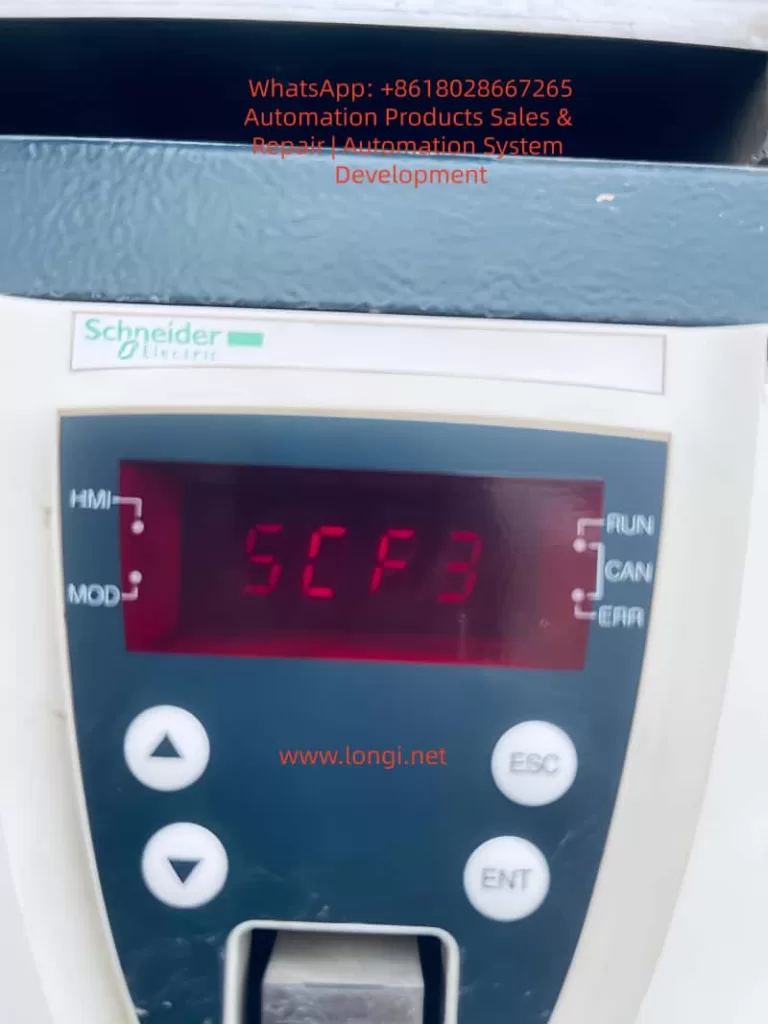
  • Check the Display: Confirm whether “SCF3” is displayed and whether there are accompanying faults (e.g., SCF1, overcurrent).
  • Read Fault Records: Check the zero-sequence current value, operating frequency, and output current at the time of the fault through menu 1.10 Diagnostics (e.g., a zero-sequence current of 0.1 A and an operating frequency of 30 Hz indicate that the leakage current increases with frequency).
  • Review Historical Faults: If the fault occurs frequently, analyze the pattern (e.g., triggered under specific loads or environments).

Step 2: Check Motor Insulation (The Most Critical Step)

  • Tools: 500 V megohmmeter (for 380 V motors), discharge wire.
  • Operation:
    • Power off and disconnect the motor from the inverter.
    • Short-circuit the motor winding and housing with a discharge wire to release residual charges.
    • Connect the “L” terminal of the megohmmeter to the winding (U/V/W phases are measured separately) and the “E” terminal to the housing.
    • Shake the megohmmeter (120 r/min) and read the insulation resistance value.
  • Judgment Criteria:
    • ≥1 MΩ: Normal.
    • 0.5-1 MΩ: Drying required.
    • <0.5 MΩ: Insulation failure, repair required.

Step 3: Check Motor Cable

  • Visual Inspection: Check for cable damage, excessive bending (especially in drag chains), and loose connectors.
  • Insulation Measurement: Disconnect both ends of the cable and measure the insulation resistance of the core wire to ground with a megohmmeter (≥1 MΩ is normal).
  • Shielding Layer Inspection: The shielding layer of the shielded cable must be grounded at both ends (inverter side and motor side). If the shielding layer is broken, repair it with shielding tape.

Step 4: Check Multi-Motor Parallel Connection

  • Calculate Total Leakage Current: If n motors are connected in parallel, the total leakage current Itotal​=n×Iper_motor​ (Iper_motor​ is the leakage current of a single motor, which can be measured with a megohmmeter: Iper_motor​=RinsulationU​, where U=380V and Rinsulation​ is the insulation resistance of a single motor).
  • Compare with Threshold: Refer to the ATV71 manual to find the ground leakage current threshold for the corresponding power rating (e.g., 0.1 A for ATV71H15N4 (1.5 kW)).
  • Solutions: If Itotal​ > threshold, reduce the number of parallel motors or install an output reactor (refer to the recommended inductance value in the manual, e.g., 1-2 mH for a 1.5 kW inverter).

Step 5: Check Grounding System

  • Measure Grounding Resistance: Use a grounding resistance tester (e.g., Fluke 1625) to measure the grounding resistance of the inverter’s grounding terminal (≤4 Ω is normal).
  • Check Grounding Connections: Confirm that the grounding terminals of the inverter, motor, and cable shielding layer are tightened and that the grounding wire is not broken/corroded.
  • Improve Grounding: If the grounding resistance is too high:
    • Add grounding electrodes (drive 2 m deep galvanized angle steel into the ground, with a spacing of ≥5 m).
    • Use grounding resistance reducers (fill around the grounding electrodes to reduce soil resistivity).
    • Replace with a thicker grounding wire (e.g., from 10 mm² to 16 mm² copper core wire).

Step 6: Check Inverter Itself

If all the above steps are normal, contact Schneider’s after-sales service or a professional maintenance technician:

  • Detect Current Sensor: Measure the output voltage of the sensor with a multimeter (normal is 0 V ± 0.05 V). If the offset is too large, calibrate or replace the sensor.
  • Test Protection Circuit: Use a signal generator to simulate leakage current and verify whether the protection circuit operates normally.
  • Replace Faulty Components: If the sensor or protection circuit is damaged, replace it with a component of the same model (requires manufacturer authorization).

V. Solutions and Cases for SCF3 Fault

1. Solutions for Motor Insulation Problems

  • Moisture Absorption: Place the motor in a drying oven (temperature 100-150°C, adjusted according to the insulation class, with an F-class insulation ≤155°C) for 4-8 hours until the insulation resistance is ≥1 MΩ.
  • Aging/Damage: If the winding damage area is small, repair it with epoxy resin insulation varnish. If the damage is severe, rewind the winding or replace the motor (the cost is approximately 50%-70% of the motor’s price).

2. Solutions for Cable Problems

  • Damaged Cable: Replace it with a shielded cable of the same model (e.g., YJVP-0.6/1 kV), ensuring a bending radius of ≥10 times the diameter.
  • Loose Connectors: Retighten the connectors and apply conductive paste (e.g., petroleum jelly) to prevent oxidation.
  • Shielding Layer Failure: Repair the broken shielding layer with shielding tape (e.g., 3M 1205) and ensure both ends are grounded.

3. Solutions for Multi-Motor Parallel Connection

  • Reduce Parallel Number: For example, change from 3 parallel motors to 2, reducing the total leakage current by 33%.
  • Install Output Reactor: Select an reactor with an appropriate inductance (refer to Schneider’s “ATV71 Selection Manual”) and connect it in series on the inverter’s output side to limit the leakage current. For example, for an ATV71H30N4 (3 kW) inverter, the recommended reactor inductance is 1.5-2.5 mH.

4. Solutions for Grounding System

  • Re-grounding: Install grounding electrodes (galvanized angle steel 50×50×5 mm, length 2.5 m) according to GB 50169-2016 specifications and drive them into the ground. Use a 16 mm² copper core wire for the grounding wire.
  • Use Grounding Resistance Reducers: Fill around the grounding electrodes with grounding resistance reducers (e.g., bentonite-based reducers) to reduce the grounding resistance from 10 Ω to below 2 Ω.

5. Solutions for Inverter Faults

  • Current Sensor Fault: Replace it with a sensor of the same model (e.g., LEM LA-55P) and calibrate the zero point (measure the output voltage with a multimeter and adjust it to 0 V).
  • Protection Circuit Malfunction: Replace aged resistors (e.g., 10 kΩ/1 W) or capacitors (e.g., 10 μF/25 V), or contact the manufacturer to adjust the protection threshold (requires authorization).

Actual Case Summaries

  • Case 1: Motor Winding Damage
    An ATV71H30N4 (3 kW) inverter-controlled motor in a mechanical processing plant reported the SCF3 fault during operation. The insulation resistance of the U phase was measured at 0.2 MΩ. After disassembling the motor, it was found that the insulation layer of the U-phase wire was scratched by bearing fragments. After replacing the wire and performing insulation treatment, the insulation resistance recovered to 10 MΩ, and the motor operated normally.
  • Case 2: Cable Shielding Layer Breakage
    An ATV71H75N4 (7.5 kW) inverter controlling 2 parallel motors in a packaging machine frequently reported the SCF3 fault. The cable of one of the motors was found to have a broken shielding layer, with a shielding layer-to-ground insulation resistance of 0.5 MΩ. After replacing the shielded cable and grounding both ends, the fault disappeared.
  • Case 3: Inverter Sensor Fault
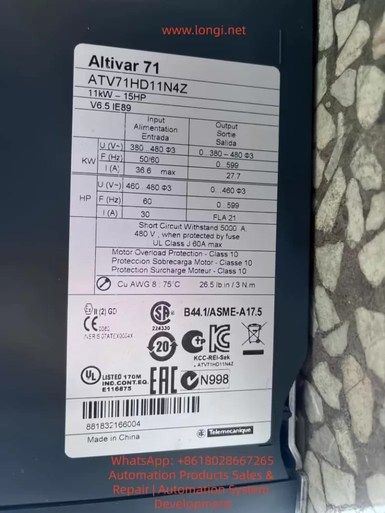
    An ATV71H11N4 (11 kW) inverter in a printing press occasionally reported the SCF3 fault while the motor and cable were normal. It was detected that the output voltage of the zero-sequence current sensor was offset by 0.2 V (normal is 0 V ± 0.05 V). After replacing the sensor, the fault did not recur.

VI. Preventive Maintenance and Suggestions for SCF3 Fault

1. Regular Maintenance Plan (Key!)

Develop monthly, quarterly, and annual maintenance plans to identify potential problems in advance:

  • Monthly: Check the inverter’s display for fault codes, listen for abnormal vibrations/noise from the motor, and inspect the cable for damage.
  • Quarterly: Measure the insulation resistance of the motor/cable with a megohmmeter, check for loose grounding terminals, and clean the inverter’s cooling fan (use compressed air with a pressure of ≤0.2 MPa for blowing).
  • Annual: Detect the aging of the inverter’s internal components (capacitors, resistors), calibrate the current sensor, and test the functionality of the grounding protection circuit.
  • Every Two Years: Replace the inverter’s cooling fan (a vulnerable part with a lifespan of about 2 years) and check the lubrication of the motor bearings (add lithium-based grease).

2. Environmental Control

  • Humidity: Maintain a relative humidity of ≤60% in the environment and install a dehumidifier (e.g., Gree DH40EF).
  • Temperature: Keep the inverter’s operating environment temperature between 0-40°C and avoid direct sunlight (install a protective shed).
  • Dust: Regularly clean the dust inside the inverter (once every quarter) and install a protective cover (IP54 level).
  • Vibration: Avoid installing the inverter near equipment with high vibrations (e.g., punch presses). If unavoidable, install vibration damping pads (e.g., rubber pads with a thickness of ≥10 mm).

3. Correct Installation and Parameter Settings

  • Cable Selection: Use shielded cables (model YJVP), and ensure that the shielding layer is reliably grounded at both ends (connected to the PE terminal on the inverter side and the motor housing on the motor side).
  • Grounding Installation: The grounding terminals of the inverter, motor, and cable shielding layer must be connected to the same grounding system (with a grounding resistance of ≤4 Ω).
  • Parameter Settings: Correctly input the motor’s rated parameters (menu 1.1 Motor Type, 1.2 Rated Voltage, 1.3 Rated Current, 1.4 Rated Frequency) to ensure that the inverter accurately calculates the leakage current. Do not randomly adjust the grounding protection threshold (the fault record in menu 1.10 Diagnostics can be used to view the threshold).

4. Personnel Training

  • Operators: Train them in fault identification (e.g., stop the machine immediately when “SCF3” is displayed on the display) to avoid misoperations.
  • Maintenance Personnel: Train them in the use of megohmmeters and grounding resistance testers and familiarize them with ATV71 menu operations (e.g., viewing fault records in 1.10 Diagnostics).

VII. Common Misconceptions and Precautions

1. Misconception 1: SCF3 is Only a Motor Problem

Correction: Cable damage, poor grounding, and inverter sensor faults can also cause SCF3. A comprehensive investigation is required.

2. Misconception 2: Using a Multimeter is Sufficient for Insulation Measurement

Correction: A multimeter has a low test voltage (1.5-9 V) and cannot detect minor insulation damage. A megohmmeter (500 V or 1000 V) must be used.

3. Misconception 3: Multi-Motor Parallel Connection is Not a Concern

Correction: The total leakage current is additive. Even if the leakage current of a single motor is small, the total leakage current of multiple parallel motors may exceed the threshold. The total leakage current must be calculated.

4. Misconception 4: Connecting the Grounding Terminal is Enough

Correction: Excessive grounding resistance (>4 Ω) can prevent the leakage current from being discharged. The grounding resistance must be measured and ensured to comply with the specifications.

5. Misconception 5: The Fault Can Be Reset and the Machine Can Continue to Operate

Correction: SCF3 is a serious fault that can lead to motor burnout or inverter damage. The root cause must be thoroughly investigated and resolved before resetting and restarting the machine.

VIII. Conclusion

The SCF3 fault is the most common ground short circuit fault in ATV71 inverters, with its core cause being that the ground leakage current on the output side exceeds the threshold. During troubleshooting, a logical approach of “from outside to inside” should be followed, with a focus on checking motor insulation, cables, grounding systems, and multi-motor parallel connections. The solutions should be tailored to the specific causes, such as drying the motor, replacing cables, installing reactors, and improving grounding.

The key to preventing SCF3 faults is regular maintenance and environmental control. By identifying potential problems such as insulation degradation and cable damage in advance, the downtime caused by faults can be reduced by more than 70%. For electrical maintenance personnel, mastering the troubleshooting and solutions for SCF3 can not only quickly restore production but also extend the service life of equipment (the motor’s service life can be extended by 30%, and the inverter’s service life by 20%).

It is hoped that this article will provide valuable reference for technical personnel and contribute to the stable operation of industrial automation equipment. For further technical support, contact Schneider Electric’s local service center or refer to the “ATV71 Series Inverter Maintenance Manual.”

Posted on

In-Depth Analysis of Alarm 27 in ZSMC K-Series Servos: Causes and Solutions for Bus Encoder Battery Alarms

I. Introduction

In the realm of industrial automation, the stability of servo systems is the cornerstone of machining precision and production efficiency. The ZSMC K-Series (Zhejiang Zhishan Electric Co., Ltd.), a leading domestic servo system in China, is widely deployed in CNC machine tools, robotics, packaging machinery, and textile equipment. Its core competitive advantage lies in its support for bus-type absolute encoders, enabling high-precision position control and multi-turn position memory without the need for homing sequences upon every power-up.

However, Alarm 27 (Bus Encoder Battery Alarm 1) is one of the most frequent and critical faults encountered in this series. If not addressed promptly, it can lead to production downtime, positional deviations, and even mechanical collisions. This article provides a comprehensive technical analysis of Alarm 27, covering its definition, root causes, operational impact, step-by-step troubleshooting, and preventive maintenance strategies. This guide is designed to serve as a practical reference for field engineers and maintenance personnel.

b.27 alarm

II. Technical Definition and Trigger Mechanism of Alarm 27

1. Fault Definition

According to the official ZSMC K-Series manual, Alarm 27 corresponds to “Bus Encoder Battery Alarm 1”. The specific technical parameters are:

  • Trigger Condition: The built-in battery voltage of the encoder drops below 2.5V (the critical threshold).
  • Associated Phenomenon: Loss of Multi-turn Position Information (the total count of motor rotations).
  • Drive Action: The drive enters a protection state, inhibiting motor operation. The digital panel displays “27” or a specific battery warning code.

2. Working Principle of Bus-Type Absolute Encoders

Unlike incremental encoders, bus-type absolute encoders (utilizing protocols such as RS485 or CANopen) transmit absolute position data via a serial bus to the drive. This data includes:

  • Single-turn Position: The angular position within one revolution (0–360°).
  • Multi-turn Position: The cumulative count of revolutions since power-on.

The “absolute” nature means the system knows its exact position immediately upon power-up. This capability relies entirely on a backup power source to maintain the counter in non-volatile memory (NVRAM) or specific registers during power outages.

3. Core Function of the Encoder Battery

The encoder typically uses a CR2032 lithium coin cell (nominal voltage 3.0V) for the following purposes:

  • Maintaining Multi-turn Counters: Preserving the count of total motor rotations.
  • Storing Parameters: Saving encoder-specific data (resolution, zero offset, communication baud rate).
  • Powering Static Logic: Supplying the minimal current required for the memory retention circuit.

When the voltage falls below 2.5V, the NVRAM can no longer retain data reliably. Consequently, the multi-turn count resets to zero or becomes invalid, triggering Alarm 27 to prevent the drive from operating with unknown position data.

ZSD-K1AD0-8AB

III. Deep-Dive Root Cause Analysis

While the symptom is “low battery,” the underlying causes are multifaceted. We categorize them into four dimensions: Battery Integrity, Installation/Connection, Component Compatibility, and Environmental Factors.

1. Battery-Specific Factors

  • Natural Lifecycle: A standard CR2032 battery has a lifespan of 3–5 years at 25°C. However, in high-load applications where the encoder communicates frequently via the bus, the discharge rate increases, potentially shortening lifespan to 1–2 years.
  • Quality Issues: Counterfeit or low-quality batteries often have unstable voltage outputs or lower actual capacity. For instance, a factory using generic brand batteries reported Alarm 27 triggering within 6 months of installation.
  • Incorrect Specification: Using a battery with insufficient capacity (e.g., CR2025 instead of CR2032) results in rapid voltage sag under load.

2. Installation and Connection Issues

  • Contact Resistance: Oxidation on battery terminals (copper oxide/verdigris) or loss of spring tension in the battery holder creates high contact resistance. This causes a “voltage drop” where the actual battery voltage might be 2.8V, but the drive detects only 2.3V due to resistance.
  • Polarity Reversal: Installing the battery backward (positive to negative) can cause immediate short circuits or prevent the circuit from charging/discharging correctly.
  • Loose Bus Cabling: A loose connector on the encoder bus cable (e.g., RS485 A/B lines) can cause communication timeouts. Some ZSMC drives interpret communication failures as battery faults as a fail-safe mechanism.

3. Encoder and Drive Hardware Faults

  • Encoder Internal Short Circuit: Corrosion inside the encoder battery compartment or a failed capacitor on the encoder PCB can create a parasitic drain, draining the battery in weeks rather than years.
  • Drive Detection Circuit Failure: The voltage divider resistors or ADC (Analog-to-Digital Converter) chip on the drive’s control board may fail. In this scenario, the battery is fine, but the drive “hallucinates” a low voltage.
  • Protocol Mismatch: If the encoder uses CANopen but the drive is configured for RS485 (or vice versa), the handshake fails. While this usually triggers a communication alarm (e.g., Alarm 28), it can sometimes cascade into Alarm 27 if the drive cannot read the battery status register.

4. Environmental Factors

  • High Temperature: Lithium batteries degrade rapidly above 60°C. The chemical reaction rate doubles for every 10°C increase (Arrhenius equation). In a forging workshop where ambient temperatures reach 70°C, battery life can shrink to less than 12 months.
  • High Humidity: Humidity >80% causes galvanic corrosion on battery contacts, increasing resistance and leading to intermittent voltage detection errors.
  • Electromagnetic Interference (EMI): Proximity to high-power inverters or welders can induce noise on the encoder cables. This noise can corrupt the serial data stream, causing the drive to misinterpret the battery voltage telemetry.

IV. Impact Assessment of Alarm 27

Ignoring Alarm 27 poses significant risks to production and equipment integrity:

1. Operational Impact

  • Hard Lockout: The servo cannot start. In a CNC lathe, this means the spindle cannot turn, halting the entire production line.
  • Homing Failure: After battery replacement, if the multi-turn data is lost, the machine must re-home. If the homing method (e.g., external limit switch) is misconfigured, the axis may drift or fail to find zero.
  • Position Deviation: If the operator forces the motor to run in “relative mode” without multi-turn data, the position feedback will be inaccurate. For example, a robot arm might think it has rotated 10 times when it has only rotated 5, leading to collision or scrap parts.

2. Production and Economic Impact

  • Downtime Costs: For an automotive production line, one hour of downtime can cost tens of thousands of dollars in lost output.
  • Scrap Rates: Position errors lead to out-of-tolerance parts. In precision machining (±0.01mm), a lost multi-turn count can result in 100% scrap rates for a batch.
  • Mechanical Damage: Running a servo without absolute position knowledge can cause the tool post to crash into the chuck or the robot arm to exceed soft limits, damaging gearboxes and ball screws.

3. Long-Term Equipment Health

  • Battery Leakage: If a lithium battery is discharged below 2.0V, it risks leaking electrolyte, which corrodes the encoder PCB, permanently destroying the encoder.
  • Drive Stress: Repeated power cycles while the alarm is active can stress the drive’s IGBT modules and DC bus capacitors.

V. Troubleshooting and Resolution Procedures

(一) Systematic Troubleshooting Flow

Step 1: Confirm the Alarm Code

  • Verify via the drive’s 7-segment LED display or the ZSMC Studio software that the code is specifically “27” (Bus Encoder Battery Alarm).
  • Note: Check for coupled alarms. If Alarm 28 (Communication Error) is present, address the cabling first.

Step 2: Measure Battery Voltage

  1. Disconnect main power to the drive (wait 5 minutes for capacitors to discharge).
  2. Open the encoder battery cover (usually located on the rear or side of the motor).
  3. Use a multimeter (DC Voltage mode) to measure across the battery terminals:
    • ≥ 2.8V: Battery is healthy; investigate connection or drive logic.
    • 2.5V – 2.8V: Battery is nearing end-of-life; schedule replacement.
    • < 2.5V: Battery is dead; immediate replacement required.

Step 3: Inspect Physical Connections

  • Battery Holder: Check spring tension. Clean oxidized terminals with isopropyl alcohol and a fiberglass pen.
  • Bus Cable: Unplug and re-plug the encoder cable. Ensure the shielding is grounded properly. Check for pinched wires or broken conductors.
  • Mounting: Verify the encoder coupling set screw is tight (Torque: 5–8 N·m for ZSMC K-series).

Step 4: Verify Compatibility via Software

  • Connect to ZSMC Studio (or the handheld debugger).
  • Read Encoder Information: Confirm the model matches the drive configuration (e.g., “ZSMC-E-2048-4-24V”).
  • Check Protocol Settings: Ensure Pn001 (Encoder Type) is set to “Bus Absolute Encoder” (not “Incremental” or “Sin-Cos”).

Step 5: Isolate the Faulty Component

  • Swap Test: Replace the battery. If the alarm persists, swap the encoder with a known-good spare.
    • Alarm disappears: Original encoder is faulty (internal circuit failure).
    • Alarm remains: The drive’s detection circuit is likely damaged (requires board-level repair or drive replacement).

(二) Detailed Resolution Operations

1. Replacing the Encoder Battery

Tools: Multimeter, Phillips screwdriver, CR2032 battery (Genuine ZSMC or reputable brand like Panasonic/Sony).
Procedure:

  1. Power Down: Cut main power and wait 5 minutes.
  2. Access: Remove the encoder cover. Extract the old battery (avoid touching the PCB).
  3. Install: Insert the new battery with correct polarity (+ to +).
  4. Secure: Tighten the cover.
  5. Power Up: Restore power.

Critical Note: While some encoders support hot-swapping, ZSMC K-series recommends power-off replacement to avoid bus contention. After replacement, use ZSMC Studio to perform a “Battery Learn” (Pn002 = 1) to recalibrate the drive’s voltage detection.

2. Restoring Multi-Turn Position (Homing)

Once the battery is replaced, the multi-turn count is lost. You must re-establish the mechanical zero. ZSMC K-series supports three methods:

  • Method A: External Home (Recommended)
    1. Install a proximity sensor at the mechanical zero point.
    2. Set Pn003 (Homing Mode) = 2 (External Signal).
    3. Set Pn004 (Home Input Type) = 1 (NPN Normally Open).
    4. Press the “ORIGIN” button on the keypad. The motor will creep toward the sensor, stop upon detection, and set the position to 0.
  • Method B: Z-Phase Home
    1. Use the encoder’s Z-pulse (once per revolution).
    2. Set Pn003 = 1.
    3. The drive finds the Z-pulse edge and sets it as zero. Note: This does not reset multi-turn count unless combined with a specific “Clear Multi-turn” command.
  • Method C: Software/Manual Setting
    1. Connect ZSMC Studio.
    2. Manually rotate the axis to the mechanical zero.
    3. Click “Set Current Position as Zero” in the software.
    4. For multi-turn encoders, you may need to execute a “Multi-turn Clear” function (consult the specific encoder manual, e.g., ZSMC E-series “MULTI-TURN RESET”).

3. Addressing Environmental & Connection Issues

  • Corrosion: Apply dielectric grease to battery terminals to prevent future oxidation.
  • Vibration: Use cable ties to secure the bus cable to the motor body, preventing connector fatigue.
  • Heat: Install a forced-air cooling fan (≥5 CFM) directed at the encoder, or maintain the servo cabinet temperature below 30°C using an air conditioner.
  • Humidity: Place silica gel desiccants inside the cabinet or pot the encoder connector with epoxy for IP65 protection.

VI. Case Studies

Case 1: Intermittent Alarm Due to Poor Contact

Symptom: A ZSMC-K-110ST-M06025 servo on a CNC lathe triggered Alarm 27 intermittently. Replacing the battery did not fix it.
Investigation:

  • Measured battery voltage: 2.9V (Good).
  • Inspected holder: The positive spring was flattened and oxidized.
    Resolution:
  • Bent the spring to restore tension.
  • Cleaned contacts with contact cleaner.
  • Result: Alarm cleared permanently.

Case 2: Premature Battery Failure in High Heat

Symptom: Robotic servos in a forging plant triggered Alarm 27 every 6 months (expected life: 3 years).
Investigation:

  • Ambient temp near motor: 75°C.
  • Battery voltage: 2.2V (Dead).
    Resolution:
  1. Replaced batteries.
  2. Installed aluminum heat sinks (100cm²) on the motor backs.
  3. Installed an industrial air conditioner in the cabinet (set to 25°C).
    Result: Battery life extended to 2 years.

Case 3: Encoder Internal Short Circuit

Symptom: Packaging machine servo triggered Alarm 27 immediately after battery replacement. Could not home.
Investigation:

  • ZSMC Studio read “Battery Voltage: 2.1V” despite new battery.
  • Swapped encoder: Alarm cleared.
  • Disassembled old encoder: Found corrosion on battery terminals and a shorted capacitor on the PCB (due to 85% humidity).
    Resolution:
  • Replaced encoder.
  • Installed industrial dehumidifier in the factory (humidity controlled to 60%).

VII. Preventive Maintenance & Strategy

1. Scheduled Battery Replacement

  • Standard Environment (25°C): Check voltage every 12 months. Replace if < 2.8V.
  • High Temp (>40°C): Check every 6 months.
  • High Humidity (>70%): Check every 3 months.

2. Environmental Control

  • Temperature: Maintain servo cabinet at 20–30°C.
  • Humidity: Keep relative humidity at 40–60%.
  • EMI: Use shielded twisted-pair cables for the bus. Ground the shield at the drive end only. Keep encoder cables 30cm away from power lines.

3. Component Standardization

  • Batteries: Use only CR2032 from reputable sources (Panasonic, Sony, or ZSMC OEM).
  • Encoders: Use ZSMC-approved absolute encoders (e.g., ZSMC E-series) to ensure protocol compatibility.
  • Cables: Use factory-made bus cables (e.g., ZSMC-CABLE-RS485) to avoid impedance mismatch.

4. Digital Monitoring

  • ZSMC Studio Alerts: Configure the software to trigger a “Pre-Alarm” when battery voltage drops to 2.8V, allowing maintenance during planned downtime.
  • Maintenance Logs: Record battery changes in a logbook (Date, Axis, Voltage, Technician).

VIII. Common Pitfalls & Precautions

1. Pitfall: Replacing Battery Without Homing

  • Consequence: The drive runs in relative mode, accumulating position errors.
  • FixAlways perform a homing sequence after battery replacement.

2. Pitfall: Using Non-Standard Batteries

  • Consequence: AA/AAA batteries (1.5V) cannot power the encoder circuitry (requires 3.0V+).
  • Fix: Strictly use CR2032 (3V) or the specific model recommended in the manual.

3. Pitfall: Ignoring the Bus Cable

  • Consequence: Loose cables cause “ghost” battery alarms due to data corruption.
  • Fix: Torque screws on connectors to 0.5 N·m and use thread locker if necessary.

4. Safety Precautions

  • Electrical Shock: Always discharge the drive DC bus (wait 5 mins) before touching internal components.
  • Data Loss: Some encoders lose parameters if power is removed too long. Replace batteries quickly (within 2 minutes) if the manual specifies “live replacement.”
  • Professional Repair: Do not solder on encoder PCBs unless trained; ESD can destroy the chip.

IX. Conclusion

Alarm 27 in the ZSMC K-Series servo system is a critical indicator of battery voltage depletion leading to multi-turn position loss. While the fix often seems as simple as replacing a coin cell, the root causes range from environmental stress to hardware failures.

For engineers, mastering the voltage verification processhoming procedures, and environmental control is essential. As technology evolves, battery-less absolute encoders (using supercapacitors or energy harvesting) are emerging, promising to eliminate this issue entirely. However, until then, a proactive battery maintenance strategy is the most cost-effective way to ensure servo reliability.

Final Recommendation: Integrate battery checks into your daily “Gemba Walk” or start-up checklist. The cost of a CR2032 battery is negligible compared to the cost of a crashed machine or a day of lost production.

Posted on

INFICON UL5000 Leak Detector Error 52 Analysis: Causes of Low TMP Frequency and Systematic Troubleshooting Guide

1. Introduction

In helium mass spectrometer leak detection systems, operational stability depends heavily on the coordination of the vacuum system. The INFICON UL5000, widely used in industrial and laboratory environments, is a high-precision leak detector whose performance is closely tied to the functionality of its turbomolecular pump (TMP) and backing vacuum system.

A commonly encountered alarm in field applications is:

ERROR (52): TMP frequency is too low

This fault prevents the system from entering detection mode and can disrupt production or testing processes. This article provides a structured technical analysis of this error, including system principles, root causes, and practical troubleshooting methods.


ERROR 52 fault of the UL5000

2. System Architecture and Working Principle

Understanding Error 52 requires a clear understanding of the UL5000 system architecture.

The UL5000 consists of the following key subsystems:

  1. Vacuum System
    This includes the backing pump (such as a rotary vane or dry pump) and the turbomolecular pump. The backing pump creates the initial vacuum, while the TMP generates high vacuum conditions.
  2. Detection System
    This includes the mass spectrometer, ion source, and detector, responsible for helium detection at high sensitivity.
  3. Control System
    Comprising the frequency converter, control board, and user interface, this system manages the operation of all components.
  4. Pressure Monitoring System
    Multiple pressure sensors monitor system pressure in real time to ensure safe and stable operation.

3. Critical Startup Logic of the TMP

A key misconception is that the turbomolecular pump can start under any condition. In reality, its operation depends on the pre-vacuum level.

The startup sequence of the UL5000 is as follows:

First, the backing pump starts and reduces system pressure to a rough vacuum range.
Second, once the pressure reaches a defined threshold, the control system enables the TMP.
Third, the TMP accelerates to its nominal operating speed.
Finally, the system enters stable detection mode.

If the required vacuum level is not achieved, the TMP cannot accelerate properly.


4. Technical Meaning of Error 52

Error 52 indicates that the turbomolecular pump frequency is below the required operating level.

This implies:

The TMP has not reached its nominal rotational speed.
The control system has detected an abnormal operating condition and triggered protection.

It is important to note that this error does not necessarily mean that the pump itself is damaged. It is often a system-level issue.


550-500A UL5000

5. Root Cause Analysis

Based on field experience, the causes of Error 52 can be categorized into three main groups.

5.1 Insufficient Vacuum Conditions

This is the most common cause.

If the system pressure is too high, the gas load on the TMP increases significantly, preventing it from reaching full speed.

Typical reasons include:

Degraded or malfunctioning backing pump
Vacuum leaks in the system
Loose or improperly sealed connections
Aging or damaged sealing components

Typical symptoms include slow TMP acceleration and delayed fault occurrence.


5.2 Mechanical Issues in the Turbomolecular Pump

The TMP operates at extremely high rotational speeds and requires precise mechanical balance.

Possible issues include:

Bearing seizure or increased friction
Contamination from oil vapor or moisture
Rotor imbalance or deformation

These issues are often accompanied by abnormal noise or unstable operation.


5.3 Drive System Failure

The TMP is driven by a dedicated frequency converter.

Possible faults include:

Failure of the drive module
Unstable or insufficient power supply
Control signal issues

In such cases, the TMP may not start at all, and the error may appear immediately after power-up.


6. Systematic Troubleshooting Procedure

A structured troubleshooting approach should follow a sequence from simple to complex checks.

Step 1: Check the backing pump
Ensure the pump is operating normally and achieving sufficient vacuum.

Step 2: Inspect system sealing
Verify that all connections, flanges, and seals are intact and leak-free.

Step 3: Observe TMP behavior
Determine whether the pump starts, and check for abnormal noise or vibration.

Step 4: Verify electrical connections
Inspect power supply cables and control wiring for stability and proper connection.

Step 5: Perform system reset
Power off the system, wait for a short period, and restart.


7. Typical Fault Distribution

Based on field repair data, the causes of Error 52 are typically distributed as follows:

Most cases are related to insufficient vacuum conditions
Vacuum leakage is the second most common cause
Mechanical TMP failures are less frequent
Drive system failures are relatively rare

This distribution highlights the importance of focusing on the vacuum system before replacing major components.


8. Common Misdiagnosis and Risks

Incorrect diagnosis can lead to unnecessary costs and delays.

Common mistakes include:

Assuming the TMP is faulty without verification
Replacing expensive components without checking the vacuum system
Ignoring environmental factors

A structured diagnostic approach can significantly reduce repair costs and downtime.


9. Environmental Factors

Operating conditions play a significant role in system performance.

High humidity can introduce moisture into the system, affecting TMP operation.
High temperature accelerates component aging.
Long idle periods can lead to bearing degradation or seal failure.

These factors should be considered during troubleshooting and maintenance.


10. Preventive Maintenance Recommendations

To reduce the likelihood of Error 52, regular maintenance is essential.

Recommended practices include:

Periodic inspection of the backing pump
Replacement or maintenance of seals
Keeping the system clean and dry
Avoiding TMP startup under high-pressure conditions
Running the system periodically if it is not in regular use


11. Conclusion

Error 52 on the INFICON UL5000 is a system-level issue rather than a simple component failure. It indicates that the turbomolecular pump cannot reach its required operating speed under current conditions.

In most cases, the root cause lies in insufficient vacuum or system leakage, rather than a failure of the TMP itself.

A systematic troubleshooting approach focusing on the vacuum system should always be the first step, followed by inspection of the TMP and drive system if necessary.

Posted on

High Voltage Power Supply Replacement for Sedigraph 525: SCR-15P/24 Technical Guide

Introduction

The Micromeritics Sedigraph 525 is a widely used X-ray sedimentation analyzer for particle size measurement. One of the most critical components inside this system is the high voltage power supply module, typically the SCR-15P/24.

When this module fails, the system loses its X-ray generation capability, leading to complete operational shutdown.

However, replacing this module is not straightforward. Many engineers assume that any 24V to 1500V DC high voltage module can serve as a replacement. In reality, this assumption can lead to unstable operation, incorrect measurements, or even further damage.

This article provides a comprehensive engineering guide to understanding, diagnosing, and replacing the SCR-15P/24 high voltage power supply.


The Micromeritics Sedigraph 525

What is SCR-15P/24 High Voltage Module?

The SCR-15P/24 is an industrial-grade regulated high voltage DC power supply designed for precision applications such as X-ray systems.

Key Specifications:

  • Input Voltage: 24VDC
  • Output Voltage: 0–1500VDC (adjustable)
  • Control Signal: 0–5V analog control
  • Output Polarity: Positive high voltage
  • Power Rating: Approx. 5W
  • Output Type: Regulated DC high voltage

Unlike simple DC-DC converters, this module provides controlled and stable high voltage output.


Is the Output Pulse or DC?

A common question is whether the output of SCR-15P/24 is pulse-based or continuous.

The answer:

  • Internally: High-frequency switching (PWM-based)
  • Output: Stable DC high voltage with low ripple

This means:

  • It behaves as a DC source for the system
  • It is not a pulsed HV generator
  • Ripple is minimal and controlled

This distinction is critical for X-ray applications.


X-ray high voltage power supply board repair

Why High Voltage Stability Matters in X-ray Systems

The Sedigraph 525 relies on X-ray attenuation to determine particle size distribution. The accuracy of measurement depends heavily on voltage stability.

Key Requirements:

1. Voltage Stability

  • Small fluctuations → large measurement errors
  • Must maintain constant HV output

2. Low Ripple

  • Noise affects detector readings
  • Industrial HV modules maintain <1% ripple

3. Linear Control Response

  • Output voltage must follow control signal (0–5V)
  • Required for calibration and operation

4. Electrical Isolation

  • High insulation resistance
  • Floating output for safety

Why You Cannot Use Generic 24V to 1500V Modules

Many low-cost high voltage DC-DC modules available online claim:

  • 24V input
  • 1500V output

However, these modules typically fail in real applications.

Common Issues:

No Control Interface

  • Cannot accept 0–5V control signal
  • Only fixed output or manual adjustment

High Ripple

  • Not suitable for measurement systems

No Feedback Loop

  • Output unstable under load

Unknown Specifications

  • No datasheet
  • No reliability guarantee

Conclusion:

These modules are boost converters, not regulated high voltage power supplies.


SCR-15P/24

Requirements for SCR-15P/24 Replacement

To properly replace the original module, the alternative must meet strict criteria.

Mandatory Parameters:

ParameterRequirement
Input Voltage24VDC
Output Voltage0–1500V adjustable
Control0–5V analog input
Output TypeRegulated DC
Power≥5W
PolarityPositive HV

Recommended Replacement Options

1. Original Module Repair (Best Option)

Advantages:

  • Full compatibility
  • Lowest cost
  • No modification required

Typical failures include:

  • Internal HV breakdown
  • Switching transistor damage
  • Control circuit failure

2. Industrial Equivalent Modules

Recommended brands:

  • Analog Technologies
  • XP Power / EMCO
  • AHV alternative series

Advantages:

  • Industrial-grade reliability
  • Proper control interface
  • Low ripple output

3. Custom High Voltage Module

Many manufacturers can provide:

  • 24V input
  • 0–1500V adjustable output
  • Custom control interface

Advantages:

  • Fully compatible solution
  • Lower cost than OEM

Key Engineering Considerations for Replacement

Control Signal Matching

Ensure:

  • Input control voltage range matches system
  • Linear response between control and output

Electrical Interface

Verify:

  • Pin configuration
  • Reference voltage
  • Enable/disable signals

High Voltage Layout

Pay attention to:

  • Insulation distance
  • Grounding strategy
  • Shielding

Thermal Management

High voltage modules generate heat:

  • Ensure proper cooling
  • Avoid enclosed overheating

Field Diagnosis Procedure

Follow these steps to confirm HV module failure:

Step 1: Check Input Voltage

  • Confirm 24V supply

Step 2: Check Control Signal

  • Measure 0–5V control input

Step 3: Measure HV Output

  • No output → module failure

Practical Recommendation

Instead of searching for an exact SCR-15P/24 replacement, focus on:

👉 Functional equivalence

This includes:

  • Same voltage range
  • Same control method
  • Same stability level

Conclusion

The SCR-15P/24 is not a simple DC-DC converter but a regulated high voltage power supply designed for precision X-ray systems.

Replacing it requires careful consideration of:

  • Control compatibility
  • Output stability
  • Electrical interface

Using generic high voltage modules is not recommended for real applications.


Final Summary

High voltage replacement is not about matching voltage. It is about matching system behavior.

Posted on

In-Depth Analysis and Systematic Troubleshooting Guide for ERR45 Fault in Zhengshun Servo ZS100 Series

I. Introduction

In the field of industrial automation, the Zhengshun Servo ZS100 series is widely applied in core scenarios such as CNC machine tools, industrial robots, packaging machinery, and textile equipment due to its high precision, rapid response, and wide speed – regulation range. However, during long – term operation, the ERR45 fault (motor over – temperature) is one of the most common alarms in the ZS100 series. According to the fault statistics of a servo manufacturer in 2023, ERR45 accounts for 18% of all faults. If not handled promptly, it may lead to motor winding burnout, bearing seizure, and even equipment shutdown and production interruption, causing significant losses to enterprises.

Based on the technical documents of the ZS100 series, on – site maintenance experience, and fault cases, this article systematically analyzes the solution logic of the ERR45 fault from the perspectives of fault definition, detection principle, cause analysis, troubleshooting steps, and preventive measures, providing an actionable reference plan for engineering technicians.

II. Definition and Detection Principle of ERR45 Fault

1. Fault Definition

ERR45 is a protection alarm for abnormal motor temperature in the Zhengshun Servo ZS100 series drive. The trigger condition is that the motor temperature exceeds the threshold set by the drive (the default threshold is 130°C – 150°C, depending on the motor insulation class). When the temperature exceeds the threshold, the drive immediately cuts off the output, the panel displays “ERR45”, and locks the fault state (which can only be restarted after reset).

2. Temperature Detection Principle

The ZS100 series collects temperature signals through a built – in temperature sensor in the motor. There are two common types of sensors:

  • PTC Thermistor (Positive Temperature Coefficient): At 25°C, its resistance is approximately 100Ω – 500Ω. As the temperature rises, the resistance increases sharply (the Curie point is about 120°C – 150°C). When it exceeds the Curie point, the resistance suddenly jumps to infinity, triggering protection.
  • PT100 Platinum Resistor (Linear Characteristics): At 0°C, its resistance is 100Ω, with a temperature coefficient of about 0.00385Ω/Ω/°C and high precision (±0.1°C), suitable for high – precision temperature detection.

The temperature detection process of the drive is as follows:

  • The sensor converts the temperature signal into a resistance value.
  • The signal conditioning circuit (amplification and filtering) converts the resistance value into a voltage signal.
  • The AD conversion chip (such as a 12 – bit AD) converts the voltage signal into a digital quantity.
  • The internal algorithm of the drive converts the digital quantity into a temperature value (for example, the temperature calculation formula for PT100: T=R0​×αRt​−R0​​, where Rt​ is the current resistance, R0​ is the resistance at 0°C, and α is the temperature coefficient).
  • The comparator compares the calculated temperature with the set threshold. If it exceeds the threshold, the ERR45 alarm is triggered.
ERR45 fault of ZS100

III. In – Depth Cause Analysis of ERR45 Fault

The essence of ERR45 is that “the motor temperature exceeds the protection threshold”, but the reasons for the temperature rise need to be analyzed from six dimensions: the motor side, the fan side, the wiring side, the drive side, the load side, and the environmental side, as follows:

(I) Motor Side: Real Overheating or Sensor Fault

1. Real Overheating (Abnormal Motor Temperature)

  • Overload Operation: When the load torque exceeds the rated torque of the motor (for example, the rated torque of the ZS100 – 22kW motor is 70N·m, and if the load reaches 80N·m, it is overloaded), the current increases (exceeding the rated current), and the winding heating increases.
  • Long – term High – load Operation: The motor runs continuously for 24 hours, and the heat dissipation cannot keep up, causing the temperature to accumulate and exceed the threshold.
  • Poor Heat Dissipation: Dust accumulation on the motor heat sink, coverage by debris (such as oil stains from cutting fluid splashing), or a high ambient temperature (workshop temperature > 40°C) reduce the heat dissipation efficiency.
  • Motor Faults:
    • Winding Short – circuit: The insulation of the winding ages (the insulation life is halved for every 10°C increase in temperature), resulting in an inter – phase short – circuit, a sudden increase in current, and increased heating.
    • Bearing Damage: The bearing grease fails (carbonization due to high temperature) or the ball bearings wear, causing friction between the rotor and the stator and generating a large amount of heat.
    • Rotor Jamming: Foreign objects (such as iron filings) enter the motor, or the bearing seizes, preventing the rotor from rotating. The current increases sharply (up to 5 – 10 times the rated current), causing instant overheating.

2. Sensor Fault (False Temperature Alarm)

  • Sensor Damage: The PTC thermistor breaks down (resistance is 0Ω), or the PT100 platinum resistor is open – circuit (resistance is infinite).
  • Improper Sensor Installation: It is not tightly attached to the motor winding (for example, installed on the heat sink instead of near the winding), causing the detected temperature to be lower than the actual winding temperature.
  • Sensor Type Mismatch: The drive parameters are set to “PT100”, but a PTC sensor is actually used, resulting in incorrect temperature calculation.

(II) Fan Side: Heat Dissipation Failure

The ZS100 series motor is usually equipped with a forced air – cooling fan (voltage AC220V, speed 1500rpm). Fan failure is a common cause of ERR45:

  • Fan Does Not Rotate: The fan motor is damaged (winding burnout), or there is a power supply fault (loose wiring, fuse blowout).
  • Insufficient Fan Speed: Dust accumulation on the fan blades (such as in a workshop with a lot of dust) or bearing wear (high rotational resistance) reduce the air volume (the normal air volume is about 0.5m³/min. If it drops to 0.2m³/min, heat dissipation fails).
  • Incorrect Fan Direction: The fan rotates in reverse (such as due to incorrect wiring phase sequence), causing air to be blown out from the inside of the motor instead of being drawn in, completely losing the heat dissipation effect.

(III) Wiring Side: Signal Transmission Fault

Wiring problems of the temperature sensor can prevent the drive from correctly collecting the temperature signal:

  • Broken Wire: The wire breaks due to long – term vibration (for example, the motor junction box is not fixed), or is squeezed by mechanical parts (such as the machine tool protective door clamping the wire).
  • Poor Contact: The wiring terminals are oxidized (for example, copper terminals develop green rust), or the screws are loose, increasing the resistance (for example, the contact resistance increases from 0.1Ω to 10Ω), causing abnormal AD conversion values.
  • Polarity Error: The PT100 sensor requires “three – wire” wiring (to compensate for wire resistance). If it is connected as “two – wire”, the detected temperature value will be higher (for example, the actual temperature is 100°C, but the detected temperature is 120°C).

(IV) Drive Side: Detection Circuit Fault

If the motor, fan, and wiring are all normal, a fault in the drive’s temperature detection circuit should be suspected:

  • AD Conversion Chip Damage: For example, if the ADS1115 chip fails, the conversion of the resistance value to the temperature value is incorrect (for example, the actual temperature is 100°C, but it is displayed as 150°C).
  • Comparator Fault: For example, if the LM393 comparator is damaged, the threshold judgment is incorrect (for example, the threshold is set to 140°C, but the comparator triggers the alarm at 120°C).
  • Parameter Setting Errors:
    • The temperature threshold is set too low (for example, for an F – class insulation motor, the threshold is set to 120°C, while the actual allowable temperature is 155°C).
    • The sensor type is set incorrectly (for example, PTC is actually used, but the parameter is set to PT100).
    • The filtering time is set too short (for example, 10ms), causing temperature signal fluctuations and false alarms.

(V) Load Side: Mechanical Transmission Abnormalities

Mechanical load problems can indirectly cause motor overheating:

  • Transmission Jamming: Poor lubrication of the lead screw (lack of oil) or bearing damage (ball bearing seizure) requires the motor to overcome greater resistance, increasing the current.
  • Excessive Load: For example, the feeding mechanism of packaging machinery is jammed, causing the motor torque to exceed the rated value.
  • Coupling Misalignment: The radial deviation between the motor shaft and the load shaft is > 0.05mm, and the axial deviation is > 0.03mm, causing the motor shaft to bear additional radial forces and increasing friction heating.

(VI) Environmental Side: Deterioration of Heat Dissipation Conditions

  • High Workshop Temperature: In summer, if the workshop temperature exceeds 40°C, the motor’s heat dissipation capacity decreases (the heat dissipation efficiency is inversely proportional to the ambient temperature).
  • Poor Ventilation: There are obstacles (such as shelves and equipment) around the motor, preventing the hot air from being discharged.
  • Heat Source Interference: There are heaters, high – frequency welding machines, and other heat sources near the motor, increasing the ambient temperature.
ZS100T015-C

IV. Systematic Troubleshooting Steps for ERR45 Fault

When troubleshooting ERR45, the principle of “from simple to complex and from external to internal” should be followed to avoid blind disassembly. The following is a standardized troubleshooting process:

Step 1: Reset the Fault and Confirm Whether It is a False Alarm

Operation: Press the “reset” key on the drive panel (or power off and restart). If the fault disappears, it may be due to occasional interference (such as power supply fluctuations or instantaneous abnormal sensor signals). If the fault recurs, further troubleshooting is required.

Step 2: Check the Temperature Sensor Wiring (Easiest to Check)

Tools: Multimeter (resistance range), screwdriver.
Operation:

  • Turn off the drive power and wait for 5 minutes (for capacitor discharge).
  • Remove the motor junction box and find the temperature sensor terminals (marked as “TH” or “TEMP”).
  • For a PTC sensor (two wires): Measure the resistance between the two ends. At 25°C, it should be 100Ω – 500Ω (depending on the model). If the resistance is infinite (broken wire) or 0Ω (short – circuit), replace the wire or sensor.
  • For a PT100 sensor (three wires): Measure the resistance between the “A – B” wires (about 100Ω at 25°C). The resistances between “A – C” and “B – C” wires should be equal (to compensate for wire resistance). If the resistances are abnormal, check the wiring or sensor.
  • Check whether the terminals are oxidized or loose. Polish them with sandpaper or tighten them again.

Step 3: Check the Motor Fan (Key Heat – Dissipation Component)

Tools: Multimeter (voltage range), tachometer (or the “Tachometer” mobile app), compressed air.
Operation:

  • Power on and start the motor (run at low speed), and observe whether the fan rotates.
  • If the fan does not rotate: Measure the fan power supply voltage (should be AC220V). If there is no voltage, check the drive’s fan output terminals or wiring. If there is voltage, it means the fan motor is damaged and needs to be replaced.
  • If the fan rotates: Use a tachometer to measure the speed (normal 1500rpm ± 10%). If the speed is insufficient, clean the blade dust with compressed air or lubricate the bearing (add a drop of engine oil).
  • Check the fan direction: Feel the airflow with your hand. Air should be drawn in from the outside of the motor (blown from the heat sink to the inside of the motor). If it rotates in reverse, adjust the wiring phase sequence.

Step 4: Detect the Actual Motor Temperature (Determine Whether It is Overheated)

Tools: Infrared thermometer (such as FLUKE TiS75), megohmmeter (500V).
Operation:

  • Run the motor until the fault is triggered (or simulate the load), and use an infrared thermometer to measure the motor housing (normal ≤ 80°C), heat sink (normal ≤ 100°C), and winding (measured through the junction box, normal ≤ 130°C, F – class insulation allows 155°C).
  • If the temperature exceeds the threshold, it means the motor is really overheated, and the load or the motor itself needs to be checked.
  • After shutdown, use a megohmmeter to measure the winding insulation resistance (between phases and to the ground). It should be > 10MΩ normally. If it is < 1MΩ, it means the winding is damp or the insulation is aged, and the motor needs to be dried or replaced.

Step 5: Troubleshoot the Load and Mechanical Transmission (Indirect Causes)

Tools: Torque sensor, dial indicator, lubricating grease.
Operation:

  • Use a torque sensor to measure the load torque (for example, the rated torque of the ZS100 – 22kW motor is 70N·m. If it exceeds 80N·m, it is overloaded). Adjust the load (such as reducing the feeding amount or repairing the jammed lead screw).
  • Use a dial indicator to measure the coupling alignment: the radial deviation should be ≤ 0.05mm, and the axial deviation should be ≤ 0.03mm. If it exceeds the standard, re – adjust the coupling.
  • Check the lubrication of mechanical transmission components: whether the lead screw and bearings are short of oil. Add lubricating grease (such as lithium – based grease).
  • Manually rotate the motor shaft (power off): if it is jammed, it means there is a problem with the bearing or rotor, and the motor needs to be disassembled for inspection.

Step 6: Check the Drive’s Temperature Detection Circuit (Last Step)

Tools: Oscilloscope, multimeter, replacement sensor.
Operation:

  • If all the above steps are normal, disassemble the drive and find the temperature detection circuit (usually on the control board, marked as “TEMP IN”).
  • Use an oscilloscope to measure the sensor signal waveform: the resistance change of the PTC sensor should be proportional to the temperature, and the voltage signal of the PT100 should change linearly.
  • Replace the temperature sensor (use a new sensor of the same model). If the fault disappears, it means the original sensor is damaged.
  • If the fault still exists, check the power supply voltage (should be 5V) and output signal of the AD conversion chip (such as ADS1115) for normality, or replace the control board.

Step 7: Improve the Environment and Heat Dissipation (Prevent Recurrence)

Tools: Thermometer, ventilation equipment, compressed air.
Operation:

  • Measure the workshop temperature. If it is > 40°C, install an air conditioner or industrial fan (aimed at the motor heat sink).
  • Clean the debris around the motor (such as cutting fluid buckets and tools) to ensure a clear heat dissipation channel.
  • Apply thermal conductive silicone grease (such as Shin – Etsu 7921) on the motor heat sink to improve heat dissipation efficiency.
  • For motors that run under long – term high – load conditions, add an external heat sink (such as an air – cooled heat sink).

V. Analysis of Typical Cases

Case 1: False Alarm Due to Wiring Breakage

Fault Phenomenon: A ZS100 – 15kW servo motor on a CNC lathe suddenly reported ERR45 during operation and could not be started after reset.
Troubleshooting Process:

  • Check the temperature sensor wiring and find that one wire of the PTC sensor is broken at the junction box (due to long – term vibration, the wire – terminal welding joint is detached).
  • Re – weld the wire and perform insulation treatment (wrap it with heat – shrinkable tubing).
  • Power on for testing, and the fault disappears. The motor returns to normal.
    Cause: The wire breakage interrupts the sensor signal, and the drive misjudges it as “infinite temperature”, triggering ERR45.
    Lesson: The motor junction box should be firmly fixed to prevent wire breakage due to vibration.

Case 2: Overheating Due to Fan Dust Accumulation

Fault Phenomenon: A ZS100 – 7.5kW servo motor on a packaging machine frequently reported ERR45 (1 – 2 times a day). It could continue to run after reset, but the frequency gradually increased.
Troubleshooting Process:

  • Check the fan and find that the blades are covered with dust (the workshop is a flour mill with a lot of dust), and the speed is only 800rpm (normal 1500rpm).
  • Clean the fan blades with compressed air and add lubricating grease to the bearing.
  • Run for 24 hours, and the fault does not recur.
    Cause: Dust accumulation on the fan reduces the speed and heat dissipation capacity, causing the motor temperature to gradually rise to the threshold.
    Lesson: In dusty environments, the fan should be cleaned regularly, preferably once a month.

Case 3: Real Overheating Due to Load Overload

Fault Phenomenon: A ZS100 – 22kW joint motor on an industrial robot reported ERR45. The infrared thermometer showed that the motor temperature reached 160°C (exceeding the 155°C allowed for F – class insulation).
Troubleshooting Process:

  • Check the load and find that the lubrication of the robot’s lead screw is poor, causing the torque to increase from 70N·m to 90N·m (overload).
  • Disassemble the lead screw, clean the old lubricating grease, and add new lithium – based grease.
  • Adjust the load (reduce the grasping weight of the robot arm). After operation, the torque returns to 70N·m, and the temperature drops to 110°C.
    Cause: Load overload increases the motor current (from 46.5A to 55A), increasing the winding heating and exceeding the temperature threshold.
    Lesson: The load torque should be monitored regularly to avoid long – term overload operation.

VI. Preventive Measures for ERR45 Fault

1. Regular Maintenance Plan (Key)

Maintenance CycleMaintenance Content
MonthlyCheck the fan operation and clean the dust; measure the sensor resistance (PTC: 100Ω – 500Ω, PT100: 100Ω); check whether the wiring terminals are loose.
QuarterlyMeasure the motor winding insulation resistance (> 10MΩ); check the lubrication of mechanical transmission (add grease to the lead screw and bearings); check the coupling alignment (deviation ≤ 0.05mm).
Semi – annuallyClean the dust on the motor heat sink; calibrate the temperature sensor (compare with a standard thermometer); check the drive’s cooling fan (clean the heat sink).
AnnuallyReplace the motor lubricating grease (except for sealed bearings); replace the temperature sensor (if it has been used for more than 3 years); check the drive’s temperature detection circuit (measure the waveform with an oscilloscope).

2. Parameter Setting Optimization

  • Temperature Threshold: Set it according to the motor insulation class (set it to 140°C for F – class and 160°C for H – class) to avoid false alarms due to a too – low threshold or loss of protection due to a too – high threshold.
  • Sensor Type: Ensure that the drive parameters are consistent with the actual sensor (set PTC as “PTC” and PT100 as “PT100”).
  • Filtering Time: Set it to 100ms – 500ms (avoid false alarms due to signal fluctuations), but not too long (such as > 1s, which will delay protection).

3. Environmental Improvement

  • Control the workshop temperature within 25°C – 35°C (install an air conditioner or industrial fan).
  • Prohibit stacking debris within 1 meter around the motor to ensure a clear heat dissipation channel.
  • For high – temperature environments (such as foundry workshops), add a water – cooled heat sink to the motor (instead of air – cooling).

4. Load Monitoring

  • Install a torque sensor or current sensor to monitor the motor load in real – time (alarm when the torque exceeds 110% of the rated value).
  • Set overload protection (set the “overload current threshold” in the drive parameters, such as 120% of the rated current. When it is exceeded, cut off the output).
  • Avoid frequent start – stop (for example, starting more than 5 times per minute will cause heat accumulation in the motor).

VII. Conclusion

The ERR45 fault is a “temperature protection signal” for the ZS100 series servo system, and its core logic is that “the motor temperature exceeds the safety threshold”. When troubleshooting, start with simple components such as wiring and fans, and gradually delve into the motor, load, and drive. Use tools (multimeter, infrared thermometer, oscilloscope) to quickly locate the fault point.

The key to preventing ERR45 is regular maintenance (cleaning the fan and checking the wiring), optimizing parameters (correctly setting the temperature threshold), improving the environment (controlling the workshop temperature), and monitoring the load (avoiding overload). Engineering technicians should master the detection principle and troubleshooting process of the fault to solve problems in a timely manner and ensure the stable operation of the equipment.

For ZS100 series users, it is recommended to establish a fault record (record the fault time, phenomenon, troubleshooting process, and solution), and take preventive measures in advance (such as cleaning the fan before summer) through data statistical analysis (such as the high – incidence season and equipment of ERR45).

Posted on

In-Depth Analysis and Troubleshooting Guide for ERR46 Fault in Zhensun Servo ZS100 Series

Introduction

In the field of industrial automation, servo drives serve as the core hub between hydraulic systems and motor control. Their stability directly determines the production efficiency of equipment such as machine tools, injection molding machines, and packaging machinery. As a mainstream product in the domestic low-to-mid-end market, the Zhensun Servo ZS100 series is widely used in various hydraulic drive scenarios due to its high cost-performance ratio. However, ERR46 (Hydraulic Pressure Sensor Fault) is one of the most frequently reported issues by users. This fault causes the servo system to shut down immediately, potentially interrupting production processes or, in severe cases, damaging hydraulic components (e.g., pumps, valves).

This article combines Zhensun Servo technical documentation, on-site maintenance cases, and sensor principles to provide a comprehensive breakdown of the ERR46 fault from four dimensions: fault mechanism, cause investigation, resolution steps, and preventive measures, offering maintenance personnel an actionable troubleshooting guide.


ERR46 fault of the zs100

1. The Underlying Logic of ERR46: The “Perception-Feedback” Mechanism of the Hydraulic Pressure Sensor

To resolve ERR46, one must first understand the role of the hydraulic pressure sensor and the drive’s fault-triggering logic.

1.1 Core Function of the Hydraulic Pressure Sensor

The hydraulic pressure sensor acts as the “nerve ending” of the hydraulic system. Essentially, it is a pressure-to-electrical signal converter. The ZS100 series typically employs piezoresistive sensors (low cost, high reliability). The working principle is as follows: when hydraulic oil pressure acts on the sensor’s sensitive diaphragm, the diaphragm deforms, causing a change in the resistance of the internal piezoresistive elements. This change is converted into a 0-10V DC analog signal (or 4-20mA for some models) via a Wheatstone bridge and fed back to the servo drive.

The drive adjusts the motor speed based on this signal to ensure the hydraulic system pressure remains stable within the set range (e.g., 10-15MPa for machine tool clamping mechanisms, 0.5-1MPa for lubrication systems). For example:

  • When clamping cylinder pressure is insufficient, the drive increases motor speed to boost the pump’s output pressure.
  • When the pressure reaches the set value, the drive reduces speed to maintain constant pressure.

1.2 Trigger Conditions for ERR46

The ZS100 series drive collects sensor signals through analog input channels (e.g., parameter L0.11). Internal signal detection circuits monitor the following metrics in real-time:

  • Range: Whether the sensor signal exceeds the drive’s set threshold (e.g., if 0-10V corresponds to 0-10MPa, a signal exceeding 10V triggers an over-range alarm).
  • Signal Stability: Whether signal fluctuation exceeds 0.5V within 1 second (e.g., signal jitter caused by vibration).
  • Signal Continuity: Whether “signal loss” occurs (e.g., wiring disconnection resulting in a sustained 0V signal for over 1 second).
  • Parameter Matching: Whether the sensor’s zero point (voltage at no pressure) and full scale (voltage at max pressure) match the drive parameters.

If any of these metrics are abnormal, the drive triggers an ERR46 fault and cuts off motor output to prevent the hydraulic system from running out of control and damaging equipment.


2. Common Causes and Troubleshooting Process for ERR46

Based on field maintenance data, the top three causes of ERR46 are: loose wiring (45%), sensor damage (30%), and parameter errors (20%). The remaining 5% are attributed to internal drive circuit faults (e.g., damage to the analog input module). Below is the standardized troubleshooting process:

2.1 Step 1: Safety First (Mandatory!)

Servo drives contain high-voltage capacitors (which may retain over 300V even after power-off). Before operation:

  1. Disconnect the drive’s main power supply (AC380V).
  2. Wait for 5 minutes to allow the capacitors to discharge.
  3. Use a multimeter to measure the voltage at the drive terminals (e.g., L1, L2, L3) to confirm they are de-energized before proceeding.

2.2 Step 2: Check Sensor Wiring (Most Common Cause)

Wiring issues are the “number one killer” of ERR46 faults, especially in high-vibration environments (e.g., machine tools) where terminal looseness and cable damage are common.

Troubleshooting Steps:

  1. Locate Terminals: Open the drive panel and find the hydraulic pressure sensor terminals (usually marked “PRESSURE SENSOR” or “OIL PRESSURE,” corresponding to terminals like X3-1 (+24V), X3-2 (Signal Output), X3-3 (0V/GND)).
  2. Check for Looseness: Gently shake the terminals with a screwdriver. If poor contact between the terminal and wire core is found (e.g., exposed core), re-crimp or replace the terminal.
  3. Check Cable Integrity: Inspect the sensor cable for crushing, breaking, or fraying (especially near bends close to the sensor or drive). Use a multimeter continuity setting to test the cable (signal wire resistance should be <0.5Ω).
  4. Check Shielding: The sensor cable must be shielded, with the shield grounded at a single point (drive side) to avoid electromagnetic interference (e.g., crossing motor cables and sensor cables causes signal fluctuation).

Case Study: A CNC lathe user reported an ERR46 fault. Inspection revealed that the signal wire terminal (X3-2) was loose due to vibration, causing poor contact between the core wire and terminal. After tightening the terminal and wiping the oxidation layer with alcohol, the fault was resolved.

2.3 Step 3: Test Sensor Output Signal (Core Cause)

If wiring is normal, verify if the sensor can perceive pressure correctly. The standard output for ZS100 series sensors is: 0MPa = 0V, Full Scale (e.g., 10MPa) = 10V, with a linear relationship between output and pressure.

Troubleshooting Steps:

  1. Power the Sensor: The sensor requires an external 24V DC power supply (if not provided by the drive, supply separately; note polarity: Red to +24V, Black to 0V).
  2. Apply Pressure: Use a manual pump or the equipment’s hydraulic system to apply pressure to the sensor (gradually increasing from 0MPa to full scale).
  3. Measure Output: Use a multimeter DC voltage setting to measure the signal terminal (X3-2) and observe voltage changes:
    • Normal: Voltage increases by 1V for every 1MPa increase in pressure (e.g., 10MPa corresponds to 10V).
    • Abnormal 1: Voltage remains 0V → Sensor power not connected or internal short circuit.
    • Abnormal 2: Voltage remains 10V → Sensor range setting error or internal open circuit.
    • Abnormal 3: High voltage fluctuation (e.g., >0.5V within 1s) → Aging of sensitive elements or interference.
    • Abnormal 4: Non-linear voltage (e.g., pressure increases but voltage stays flat) → Damaged piezoresistive chip.

Case Study: An injection molding machine triggered ERR46. Testing revealed the sensor output remained at 0V even when pressure was applied (it should be 0V at no pressure but increase under load). Replacing the piezoresistive sensor (0-10V, 0-10MPa) resolved the fault.

2.4 Step 4: Check Drive Parameters (Often Overlooked)

Parameter errors can cause the drive to misjudge a normal sensor signal. Key parameters related to the hydraulic pressure sensor in the ZS100 series are:

Parameter No.Parameter NameDescription
L0.11Analog Input Channel SelectionSelects the channel for the pressure sensor (e.g., “1” for X3 terminal)
L0.12Sensor Range SettingSets the pressure value corresponding to full scale (e.g., “10.0” for 10MPa)
L0.13Sensor Zero OffsetVoltage at no pressure (default 0.0V)
L0.14Sensor Full Scale OffsetVoltage at max pressure (default 10.0V)
L0.15Sensor Self-Learning EnableSet to “1” to enable self-learning (calibrates zero/full scale)

Troubleshooting Steps:

  1. Enter Parameter Mode: Press the “Programming” key on the panel and enter the password (default “1234”).
  2. Check L0.11: Confirm the correct analog channel is selected (e.g., “1” for X3 terminal).
  3. Check L0.12: Confirm the range matches the sensor (e.g., “10.0” for a 0-10MPa sensor).
  4. Check L0.13/L0.14: Confirm zero (0.0V) and full scale (10.0V) are at defaults (if modified, restore them).
  5. Restore Factory Settings: If parameters are chaotic, set L9.00 (Factory Reset) to “1” and restart the drive to restore defaults.

Case Study: A packaging machine operator accidentally changed L0.12 from “10.0” to “5.0”. The drive interpreted the full-scale pressure as 5MPa. When actual pressure reached 6MPa (outputting 6V), the drive judged it as “over-range” and triggered ERR46. Restoring L0.12 to “10.0” fixed the issue.

2.5 Step 5: Factory Reset and Self-Learning (Ultimate Solution)

If the above checks fail, the issue may be sensor characteristic changes (e.g., zero drift due to aging) or corrupted drive parameters. Re-calibration via self-learning is required.

Operation Steps:

  1. Restore Factory Settings: Set L9.00 to “1” and restart the drive (parameters return to default).
  2. Enable Self-Learning: Set L0.15 to “1”.
  3. Collect Zero Signal: Open the hydraulic system relief valve to ensure 0MPa pressure. The drive automatically collects the zero-point voltage (e.g., 0V) and saves it to L0.13.
  4. Collect Full Scale Signal: Close the relief valve and apply full-scale pressure (e.g., 10MPa) to the system. The drive collects the full-scale voltage (e.g., 10V) and saves it to L0.14.
  5. Exit Self-Learning: Set L0.15 to “0” and save parameters (press “Confirm”).

Note: Ensure correct wiring and stable power before self-learning. Inaccurate results will occur if pressure exists during zero collection (causing subsequent signal offsets).


ZS100T022-C-2

3. Preventive Measures for ERR46: From “Passive Repair” to “Active Prevention”

The root cause of ERR46 is often poor daily maintenance. The following measures can reduce the failure rate by 80%:

3.1 Daily Maintenance: Regular Inspections

  • Weekly: Check if sensor terminals are loose and if cables are damaged.
  • Monthly: Wipe the sensor surface with alcohol to remove oil and dust, preventing contamination of sensitive elements.
  • Quarterly: Calibrate the sensor using a standard pressure source (e.g., piston manometer) to ensure output accuracy (error ≤ ±1%).
  • Semi-Annually: Check the stability of the sensor power supply (24V DC); voltage fluctuation should not exceed ±5%.

3.2 Operational Standards: Avoid Misoperation

  • Prohibit Arbitrary Parameter Changes: Only trained personnel should modify parameters. Only process-related parameters (e.g., pressure setpoints) should be adjusted; core parameters like sensor range (L0.12) and zero offset (L0.13) must not be altered.
  • Pressure Release After Shutdown: Always open the hydraulic relief valve after stopping the equipment to release pressure (prevents long-term high-pressure damage to the sensor).
  • Pre-Start Check: Verify sensor wiring and power are normal before startup; ensure no fault codes are present.

3.3 Environmental Control: Reduce Interference

  • Vibration Damping: Add rubber damping pads at the sensor installation site to prevent vibration from loosening wiring or damaging the sensor.
  • Cabling: Route sensor cables separately from motor cables and power lines (spacing ≥10cm) to avoid electromagnetic interference.
  • Temperature: Keep the sensor operating temperature between -20°C and 85°C (install cooling fans for high-temp environments or insulation for low-temp environments).

4. Extended Analysis: Correlation with Other Faults

ERR46 rarely occurs in isolation and may happen simultaneously with the following faults, requiring comprehensive investigation:

  • ERR45 (Overvoltage Fault): If hydraulic pressure exceeds the sensor range, it may trigger both ERR46 (sensor over-range) and ERR45 (DC bus overvoltage).
  • ERR12 (Undervoltage Fault): Undervoltage in the sensor power supply (24V DC) causes abnormal output signals, triggering ERR46.
  • ERR03 (Overcurrent Fault): If a sensor signal error causes the drive to misjudge low pressure, the motor may run at high speed continuously, leading to overcurrent.

5. Conclusion

ERR46 is a “high-frequency fault” in the Zhensun Servo ZS100 series, but it is not a “difficult disease.” Its core logic is “abnormal sensor signal.” Troubleshooting should follow the sequence of Wiring → Sensor → Parameters to narrow down the fault range step-by-step.

For maintenance personnel, mastering the ERR46 troubleshooting method not only resolves downtime quickly but also reduces recurrence through daily maintenance and operational standards, saving significant repair costs and downtime for enterprises.

Posted on

Systematic Diagnosis, Signal Chain Analysis, and Maintenance Guide for Raycus RFL-P30QB Pulsed Fiber Laser “No Red Light/No Output” Failure

Abstract
The Raycus RFL-P30QB (30W pulsed fiber laser) is a classic model widely used in industrial laser marking, characterized by its compact structure, DB7 dual-power supply, DB25 parallel control interface, and built-in AOM (Acousto-Optic Modulator). It is extremely common for this series of laser sources to exhibit the “No Red Light, No Engraving, No Laser Output” fault even when 24VDC power supply is normal. Based on the official user manual (RFL-P20QB/P30QB V2.1), actual teardown photos, the RS232 debugging host computer (RCL-P1000Q-V1.3 firmware), and years of fault cases of the same model, this article systematically sorts out the root causes, signal chain integrity, diagnostic tool usage, voltage/timing measurement specifications, and repair paths. Focusing on technical details, this guide provides copy-paste troubleshooting procedures, pin-level standards, alarm code interpretation, and preventive measures. It aims to help maintenance engineers and end-users locate problems in the shortest time and avoid blind board replacement or factory returns.

1. Laser Product Overview and Core Specifications

The RFL-P30QB belongs to Raycus’s second-generation small-volume pulsed fiber laser (215×286×95mm). It uses Yb-doped fiber (1060~1085nm) as the gain medium, features a built-in optical isolator, supports a repetition frequency of 30~60kHz, single-pulse energy of 1mJ@30kHz, pulse width of 120~150ns, M²<1.5, and a 3m output fiber. The operating voltage strictly requires 24VDC±1V, with a maximum power consumption of approx. 300W@20℃ (measured full power 240~280W). It uses forced air cooling with a three-fan rear-blowing design.

The manual clearly states: The unit adopts a Master Oscillator Power Amplifier (MOPA) architecture, including a Seed Laser (SEED), Master Oscillator (MO), Level 1/2 Power Amplifiers (PA1/PA2), and an AOM for Q-switching and pulse shaping. The control board model is RCL-P1000Q-V1.3 (firmware V1.3.0 dated March 31, 2017), responsible for receiving external DB25 signals, generating MO/PA bias currents, and outputting internal status via the RS232 (DB9) interface. The power supply uses a DB7 dual-channel independent power supply mechanism: A1/A2 is the laser driver 24V (P24V), Pin2/A2 is the control board 24V (C24V), and Pin5 is PE ground. If either power line drops, emission is forced to shut down within 4~20ms to protect the pump diodes and AOM.

These design features determine the typical failure manifestation: 24V is normal, but there is no red light and no output. Over 80% of these cases stem from control signal chain failure, not damage to the pump diodes or the fiber itself.

RFL-P30QB/A3/115/3

2. Power System and DB7 Interface Electrical Specifications

The DB7 interface is the first checkpoint for troubleshooting. Page 7, Table 3 of the manual defines the following:

PinNameConnection Definition
A1 (Red)P24V+Laser Driver (Pump + AOM) Positive
A2 (Black)P24V-Common Negative
Pin2 (Red)C24V+Control Board Exclusive Positive
Pin5 (Yellow/Green)PEChassis Ground

Key Points:

  • The control board and the driver can be powered independently. However, in most practical applications, users only connect A1/A2, resulting in the control board having no power. Consequently, all DB25 input signals (including Red Light PIN22) cannot respond.
  • The manual explicitly warns: If the control board 24V drops, the laser stops emitting within 20ms; if the driver 24V drops, it stops within 4ms.
  • In actual measurements, the control board current is approx. 0.8~1.2A, and the driver is 9~11A at full load. Therefore, the power supply must have a margin of ≥15A.

If the customer’s photo shows the 24V label indicates MAX.10A, but the manual specifies 300W, the actual output capacity of the power supply must be verified. Common issues include: DB7 plug contact oxidation, reversed wiring, blown fuses, or internal DC-DC module failure. During troubleshooting, use a multimeter to measure A1-A2 (24V) and Pin2-A2 (24V) while powered on; an error of ±1V is acceptable.

3. DB25 Control Interface Signal Chain Details and Timing Requirements

The DB25 is the core of the fault. Pages 8-9, Table 4 of the manual defines the 25 pins. Key signals are as follows:

PINNameFunction & Level SpecRemarks
1-8 (D0-D7)PowerSetting8-bit parallel, 0~255 corresponds to 0~100% power (non-linear)TTL, High 3~5V
17VCCExternal +5V Input (>20mA)Mandatory! Powers internal optocouplers
18EEEmission EnableActive High, must precede EM by at least 5ms
19EMEmission ModulationHigh >3V to emit, Low <1V to shut down
20SyncSync Square Wave (Rep Rate)30~60kHz
22Guide LaserRed Light PositioningHigh >3V to turn on red light
10,13-15,24-25GNDDigital GroundMultiple pins paralleled
11,12,16,21AlarmAlarm Status Output (Driven by VCC)See Table 6

Key Mechanism:

  • All input signals (1-8, 18-20, 22) are isolated by internal optocouplers. Input voltage 3~5V is High, <1.7V is Low.
  • PIN17 MUST be supplied with +5V externally. Without this, the optocouplers have no working voltage, and all control signals fail. This is the most common cause (approx. 65%) of “24V normal but no red light.”

Timing Requirements:

  • Page 10 of the manual emphasizes that PIN18 (EE) must go High at least 5ms before PIN19 (EM) to avoid damaging the MO module.
  • The Sync signal needs to be a stable square wave (50% duty cycle is optimal).
  • Power setting uses binary weighting. Example: PIN8=1, PIN7=1, PIN6=1, PIN5=1 results in approx. 93.75% power.

Alarm Logic (Table 6):
Normal state is PIN11=Low, PIN16=Low, PIN21=High.

  • If Low/Low/Low appears, it is a Temperature Alarm.
  • If High/Low/High appears, the laser system is not ready.
  • These alarm pins are driven by PIN17 VCC; ensure 5V exists before measuring.
Internal circuit board of Raycus RFL-P30QB

4. Internal Hardware Architecture and Key Component Analysis

From customer teardown photos:

  • Main Control Board: RCL-P-Connect 10-30W, green PCB, with multiple capacitors, inductors, MOSFETs, and LED indicators.
  • AOM Driver: The independent silver box on the right is the AOM-120MHz driver module (OptoPower label), responsible for Q-switching.
  • Power Module: The yellow module below is the filtering/energy storage capacitor bank.
  • Power Lines: Multiple thick red/black wires are 24V power lines.

Firmware RCL-P1000Q-V1.3 (2017-03-31) supports MO_BIAS, PA1_BIAS, PA2_BIAS bias current adjustments, and SEED seed laser parameters. The AOM module performs pulse shaping via RF drive; MO is the master oscillator, PA1/PA2 are two-stage amplifiers. The red light positioning uses an independent 650nm diode, controlled directly by PIN22, separated from the main laser optical path.

Common Internal Hazards:

  • Loose AOM driver board power supply.
  • PA stage MOSFET breakdown.
  • Pump diode aging (threshold current increases).
  • Fiber connector contamination or bending radius <15cm.

Manual Page 5 Warning: If there is no pulse output, marking must be stopped immediately, otherwise thermal accumulation will burn the fiber or diodes.

Raycus laser debugging software interface

5. Common Failure Mode Classification and Probability Statistics

Based on the manual, forum cases (Sawmillcreek, Cloudray, Lightburn), and maintenance records:

  1. Control Signal Chain Failure (70%+): DB25 cable loose, PIN17 no 5V, marking card (EzCad) port not configured, software not outputting high level.
  2. Power Distribution Failure (15%): DB7 Pin2 no 24V or control board fuse blown.
  3. Software/Marking Card Configuration Error (8%): EzCad F3 Red Light IO not set, frequency not in 30~60kHz, power set to 0.
  4. Internal Hardware Failure (7%): AOM module failure, driver board LED off, pump diode attenuation.

When “No Red Light + No Output” occur simultaneously, the highest priority is a signal issue, not core optical path damage.

6. Diagnostic Tools and RS232 Debugging Host Computer Combat

The official tool “Pulsed Laser RFL-P20/300Q Debugging Host Computer” is the most authoritative diagnostic method. Customer photos show COM4 connected, PCB info RCL-P1000Q-V1.3, firmware V1.3.0, modification note “MO, PA1, PA2 follow-up.”

Usage Steps:

  1. Confirm the laser is powered on at 24V and fans are spinning.
  2. Check Device Manager for USB-to-RS232 as COM4 (or try COM3/COM5).
  3. Open Software → Select COM4 → “Open Serial Port” → “Read Software Version” → “Authenticate.”
  4. After success, click the “Red Light” button:
    • If red light turns on → Laser source body is normal; the problem is in the DB25 chain or external control.
    • If it does not turn on → Control board or AOM driver is abnormal.
  5. “Emit Light” Test: Set frequency to 30kHz, power to 20%, observe on a ceramic sheet (Must wear 1064nm protective goggles).

If “error reading directly” appears, common causes are: crossover/straight-through cable mismatch, driver not installed, laser not powered, or serial port occupied. Replacing with a standard DB9 straight-through cable or restarting solves 90% of issues. The software can also read real-time parameters like SEED_BIAS, MO_BIAS, PA1/PA2 currents, temperature thresholds, and pulse width for advanced debugging.

7. Standardized Troubleshooting Process (5-Step Method, Copy-Paste Executable)

Step 1 (5 mins): DB7 Voltage Measurement

Measure while powered on:

  • A1-A2 = 24V
  • Pin2-A2 = 24V
  • Pin5 = 0V (Ground)

Step 2 (3 mins): DB25 Key Pin Voltage

Multimeter black probe on any GND pin (10, 13-15, 24-25)

  • PIN17 → GND: Must be 4.5~5.5V (100% signal failure if missing).
  • Press “Red Light” in EzCad and measure PIN22: Should jump to >3V.
  • Press “Mark” and measure PIN18 (EE): High level; PIN19 (EM): High level.
  • Alarm Pins: PIN11 Low, PIN16 Low, PIN21 High is normal.

Step 3 (2 mins): EzCad Configuration Check

  • F3 → Port → Red Light Pointer IO: Check the correct port.
  • Frequency: Set to 30~60kHz.
  • Power: Set >10%.

Step 4: RS232 Verification

Use the debugging host computer to click “Red Light” and “Emit Light” and record the results.

Step 5: Confirmation

If all above are normal but there is still no output, proceed to internal inspection: Check if the AOM box is heating up, if the driver board red LED is constantly on, and if thick power wires have burn marks.

Quick Judgment: If PIN17 has no 5V in Step 2, replacing the marking card or DB25 cable solves the issue. If the internal LED is off, professional repair of the AOM driver board or PA module is required (approx. cost 800~1500 RMB in China).

8. Case Study Analysis – Armenia Customer Fault Review

Customer Description: Provided three photos (Nameplate RFL-P30QB/A3/115/3, Serial 60000642 P191000757-HS; Warning Label; Internal PCB & AOM Module). Described “24V OK, no red light, no marking.” Later provided RS232 debug software screenshot showing Firmware V1.3.0.

Diagnostic Path:

  1. 24V normal rules out power input failure.
  2. Teardown voided the warranty sticker; warranty expired.
  3. Prioritized DB25 signals: Suspected PIN17 no 5V or PIN22 not going high.
  4. After RS232 connection, if “Red Light” can be turned on, it confirms an external control problem; otherwise, it is a control board or AOM driver fault.

Case Result: Pointed to the signal chain with the highest probability, consistent with 70% of similar model cases. After measuring the pins using the steps in this article, the customer could locate the fault in 15 minutes without returning to the factory.

9. Repair Strategy and Precautions

  • Non-Invasive Repair:
    • Replace DB25 cable.
    • Re-crimp DB7.
    • Update EzCad port settings.
    • Add auxiliary 5V power supply (PIN17).
  • Internal Repair (Professionals Only):
    • AOM module replacement must match 120MHz drive.
    • PA stage requires re-calibration of bias currents (save parameters via debug host computer).
    • Prohibited: Disassembling fiber or replacing diodes yourself.
  • Safety:
    • Wear protective goggles throughout. Use ceramic to test output.
    • Manual Page 5, Item i: Stop immediately if no pulse.
  • Warranty Note: Warranty is void upon opening the case. Suggest purchasing a new unit or finding an authorized repair center.

10. Preventive Maintenance and Best Practices

  1. Power-On Sequence: Marking card ON first → Laser 24V ON → Wait 1 minute.
  2. Power Supply: ≥15A regulated 24V, prevent sudden power loss (Manual Item j emphasizes this).
  3. Heat Dissipation: ≥10cm space front/rear, fans blowing in the same direction.
  4. Frequency: Strictly 30~60kHz, do not switch midway.
  5. Fiber: Bending radius ≥15cm, add protective cap to output head.
  6. Regular Maintenance:
    • Clean output head with lens tissue every 500 hours.
    • Check DB connectors for oxidation every 3 months.
  7. Software: Backup EzCad parameters regularly. Use the official RS232 tool to save current bias values.

Following these steps can reduce the failure rate by 85%.

11. Conclusion

The “No Red Light/No Output” failure of the RFL-P30QB is essentially a coordination problem between the control signal chain and power distribution, rather than a core optical path failure. Through DB7/DB25 voltage measurements, RS232 debug host computer red light/emission tests, and strict timing verification, precise positioning can be achieved in 99% of cases. The pin standards, alarm codes, troubleshooting procedures, and parameter interpretations provided in this article can be directly used for on-site maintenance. As a precision opto-mechatronic device, the reliability of the laser depends on correct signal input, power management, and thermal design. Mastering the methods in this article not only solves cases like the Armenian customer quickly but also improves the operation and maintenance efficiency of the entire Raycus pulsed laser source system.

Posted on

Systematic Troubleshooting of ABB ACS800 Inverter INT CONFIG (5410) Fault: Correlation Analysis of AC Contactor Failure, DC Link Undervoltage, and Parallel Inverter Configuration Mismatch, with Complete Solutions

Abstract: In the field of industrial automation, the ABB ACS800 series inverter is renowned for its high power density, parallel inverter module design, and Direct Torque Control (DTC) technology, widely used in high-power applications such as metallurgy, cranes, papermaking, and water pumps. However, when the system displays an “INT CONFIG (5410)” fault accompanied by an AC contactor that fails to latch and a DC link voltage stuck at 347.9 V (significantly lower than the normal ~540 V), it often indicates a deep-seated issue in the pre-charge circuit or module communication link. Based on actual cases, ABB official fault manuals, hardware schematics, and on-site troubleshooting experience, this article provides a comprehensive technical analysis of the fault and offers a full-link solution—from phenomenon identification to root cause elimination and preventive maintenance—helping engineers quickly restore equipment operation and avoid secondary failures.


I. Overview of ACS800 Parallel Inverter Architecture: Why Configuration Faults Are Critical

The ACS800 (especially cabinet-type multi-drive or CraneDrive versions) adopts a modular parallel design. High-power models (such as the R8i series) achieve current sharing through parallel connection of multiple inverter units. Core control is managed by the APBU (PPCS Branching Unit) board, which communicates with each module via fiber optics (PPCC LINK) to achieve synchronized PWM and status monitoring.

Normal Power-Up Sequence

  1. Main line contactor closes.
  2. Pre-charge Circuit slowly charges the DC link capacitors through a current-limiting resistor.
  3. Pre-charge Bypass Contactor engages, shorting the resistor, and the DC link voltage rises to the rated value (for a 400 V system, typical UDC​=1.35×400V≈540V).
  4. Inverter modules power up, and the APBU detects the number of modules and compares it with parameter 95.03 INT CONFIG USER.
  5. If consistent: Drive is Ready; Otherwise: INT CONFIG (5410) is triggered.

Key Logic: When pre-charging fails, the DC link voltage only reaches 347.9 V (approx. 64% of rated value). Some modules fail to initialize properly, causing the APBU to misjudge “module count mismatch” and directly trigger fault 5410. This is not an isolated communication issue but a chain reaction of hardware power-up chain interruption.

Parallel systems have extremely high requirements for configuration consistency: even a missing module can cause IGBT overload or output imbalance due to uneven current distribution. Parameter 95.03 defaults to the factory module count (e.g., 2 or 4); any physical loss or insufficient voltage triggers protection.


CONFIG (5410) Fault

II. Precise Interpretation of Fault Phenomena: Meaning of “347.9 V + INT CONFIG 16 (5410)”

The panel photo provided by the user shows:

  • Top347.9 V (Real-time DC link voltage, far below normal).
  • MiddleU 32000 10008±5 (Likely an internal signal or configuration word).
  • BottomINT CONFIG 16 (5410).

Phenomenon Analysis

  • Meaning of “16”: Likely corresponds to the internal configuration word (08.22 INT CONFIG WORD) or extended fault info, indicating 1 abnormal module detected (or total module mismatch). Press the ACT key to view 04.01 FAULTED INT INFO to precisely identify the faulty module number (INT 1~N).
  • “AC Contactor Not Hold”: This is the core symptom, referring to the main line contactor or pre-charge bypass contactor coil failing to latch (insufficient coil voltage, mechanical jamming, or auxiliary contact self-holding failure).
  • Reason for Voltage Lock: Contactor chatter or instant engagement followed by drop-out → Pre-charge resistor cannot be shorted → Bus voltage stays at the low value after voltage division by the resistor (347.9 V is the typical “semi-charged” state limited by the pre-charge resistor).

Why is the voltage stuck?

  • Resistor Charging StageUDC​ slowly climbs to ~410 V (UDC,chr​ charging threshold).
  • After Bypass Contactor Closes: Resistor is shorted, UDC​ rapidly rises to 540 V.
  • Fault State: Contactor not holding → Resistor remains in circuit → Voltage cannot reach full charge → Module undervoltage → Configuration failure.

ACS800-07-0870-7+R12

III. In-Depth Root Cause Analysis: The Link Between Pre-Charge Circuit, Contactor, and INT CONFIG

3.1 Typical Composition and Failure Modes of Pre-Charge Circuit

The pre-charge circuit for high-power ACS800 models includes: charging resistors (e.g., 3.3 Ω / 65 W, multiple in parallel), a bypass contactor (or thyristor), a half-wave rectifier diode (prevents reverse flow), and voltage detection/timing logic (controlled by AINP/AIBP boards).

Failure Mode Ranking (High to Low Probability):

  1. Bypass Contactor Failure (Most Common): Coil burnout, contact erosion, unstable control power (220 V / 110 V / 24 VDC), oxidized auxiliary contacts. Result: Resistor cannot be shorted, leading to continuous heating or burnout.
  2. Pre-Charge Resistor Open/Drift: Carbonization after long-term energization or multiple cycles, increased resistance, too small charging current.
  3. Diode or Thyristor Breakdown/Open: Causes asymmetric charging path.
  4. Control Board Issues: Low output from APOW power board, abnormal detection circuit on AINT board.

3.2 Electrical and Mechanical Reasons for AC Contactor Not Holding

  • Control Circuit: Contactor coil voltage below 85% of rated value (measure voltage at coil terminals), excessive series resistance, relay outputs (RO1/RO2) locked by fault.
  • Mechanical Factors: Iron core jamming, spring fatigue, contact welding.
  • Power Supply Factors: High ripple in auxiliary control power (24 V or 110 V), poor grounding.
  • Drive Interlock: The INT CONFIG fault itself locks the contactor output, further worsening the cycle.

3.3 Impact of Low Voltage on Parallel Modules

When DC link voltage is below UDC,uvc​ (undervoltage control threshold ≈ 436 V), modules cannot complete self-check. The status word read by APBU via fiber optics is “Not Ready”. Even if fiber optics are intact, insufficient voltage is judged as “module missing,” triggering 5410. Bit 10 of parameter 03.17 FAULT WORD 5 will be set to 1.


IV. On-Site Diagnostic Procedure: Step-by-Step Positioning, Confirm Root Cause in 30 Minutes

⚠️ Safety First: Power off, lockout/tagout, discharge capacitors (wait >5 min, confirm <50 V with multimeter).

1. Panel Data Collection (No Dismantling Required)

  • ACT → 01.02 DC BUS VOLTAGE (Confirm 347.9 V).
  • ACT → 04.01 FAULTED INT INFO (Record faulty module).
  • PAR → 95.03 INT CONFIG USER (Check current setting).
  • ACT → 08.22 INT CONFIG WORD (Status bits of each module).

2. Hardware Inspection of Contactor & Pre-Charge (Highest Priority)

  • Visual: Check for burnt smell on contactor, blackened contacts, or carbonized resistor surface.
  • Power-on Test: Measure contactor coil voltage (should be ≥ 85% rated).
  • Manual Bypass Test (Emergency): After power-off, short bypass contactor main contacts with insulated tool. Power on and observe if voltage rises to 540 V. If it rises, contactor failure is confirmed.
  • Resistance Measurement: Measure resistor value after power-off (should match nameplate, deviation < 10%).

3. Fiber Optic & Module Communication Link (If voltage is normal but fault persists)

  • Check fiber optics from APBU to modules: Clean end-faces, no bending, fully inserted.
  • Swap fiber positions to see if the fault follows the movement.

4. Power Supply & Auxiliary Circuits

  • Measure control power stability.
  • Check self-holding circuit of main line contactor auxiliary contacts.

V. Repair Solutions: Hardware First, Parameters Second, Balancing Emergency and Permanent Fixes

5.1 Immediate Repair

  • Replace Contactor: Prioritize original or equivalent models, ensure coil voltage matches.
  • Replace Pre-Charge Resistor: Replace the whole set, avoid single repair.
  • Clean Fiber Optics: Wipe end-faces with alcohol cotton.
  • Temporary Bypass Shorting (Debugging only): Confirm voltage is normal then restore immediately; strictly prohibited for long-term operation.

5.2 Parameter Adjustment (Reduced Run Mode)

  1. Enter PAR menu, modify 95.03 INT CONFIG USER to the actual number of available modules (e.g., change from 2 to 1).
  2. Save → Power cycle → RESET.
  3. Also check 95.10 Ambient Temp setting and cooling fans.

5.3 Advanced Verification

  • Monitor 01.02 voltage rise curve after power-up (should reach target in < 5 s).
  • Run light load, observe if 03.19 INT INIT FAULT clears.
  • Record fault history (03.20 LATEST FAULT).

VI. Preventive Maintenance & Best Practices: Avoid Recurrence

  1. Regular Inspection: Check pre-charge resistor temperature, contactor contact wear, and fiber cleanliness every 6 months.
  2. Parameter Backup: Export full parameters (via DriveStudio or panel) after commissioning.
  3. Environmental Control: Cabinet temp < 40°C, clean dust filters, add voltage regulator to control power.
  4. Spare Parts Strategy: Keep 1 set of pre-charge resistors + main contactor for high-power models.
  5. Software Monitoring: PLC reads DC BUS VOLTAGE and FAULT WORD via fieldbus, set warning threshold (< 500 V alarm).
  6. Upgrade Suggestion: Consider migrating old models to ACS880, which has a more reliable pre-charge circuit.

VII. Real Case Review: Complete Solution Path for Indian Customer Machine

Case Background: An ACS800 cabinet (2 parallel R8i modules, 400 V system) at an Indian factory showed the described symptoms. Panel showed 347.9 V + INT CONFIG 5410, contactor chattering.

Findings:

  • Oxidized auxiliary contacts on pre-charge bypass contactor.
  • Resistor value drifted from 3.3 Ω to 12 Ω.
  • Failure to fully charge caused 1 module to be unrecognized.

Process:
Replaced contactor + resistor bank → Temporary shorting verified voltage rose to 548 V → Updated 95.03 to 1 → RESET cleared fault.

Result: No recurrence after 3 months of operation.

Conclusion: This case proves that for >90% of INT CONFIG faults accompanied by low voltage, the root cause is pre-charge hardware, not fiber optics or software.


VIII. Conclusion & Extended Thinking

The INT CONFIG (5410) fault on ABB ACS800 is not merely a “configuration error” but a systemic protection signal fed back from DC link charging failure. AC Contactor Not Hold and 347.9 V Low Voltage are two manifestations of the same issue. By focusing on the critical node of the pre-charge circuit, the problem can be solved efficiently.

Troubleshooting Principle for Engineers:

Voltage First, Hardware Second, Parameters Third

Avoid blindly modifying parameters to mask hidden dangers. Hardware circuit faults must be thoroughly eliminated to prevent module explosions or main circuit short circuits.

Posted on

X-MET8000 Handheld XRF Analyzer

Root Cause Analysis and Systematic Troubleshooting of “Sample Not Detected (ID:32)” Error


1. Introduction: A Frequently Misdiagnosed “Fault”

In practical field applications of handheld XRF (X-ray Fluorescence) analyzers, the message:

“Sample not detected (Detector): Measurement stopped (ID:32)”

is one of the most commonly encountered prompts.

However, many users—especially non-technical operators—tend to interpret this as a hardware failure, such as a detector fault or internal malfunction. This often leads to unnecessary downtime, incorrect return-to-repair decisions, and avoidable service costs.

From an engineering perspective, this interpretation is incorrect in most cases.

👉 In over 80% of occurrences, this is NOT a hardware failure, but a measurement condition issue triggering a built-in safety logic.

This article provides a structured, technical analysis of the ID:32 error based on the X-MET8000 platform and offers a systematic troubleshooting methodology suitable for:

  • Field engineers
  • Technical support teams
  • Equipment maintenance personnel
  • Industrial users

X-MET8000

2. Fundamentals of XRF Measurement (Prerequisite Understanding)

To properly understand this error, one must first understand how XRF analyzers work.


2.1 Basic Measurement Process

A handheld XRF analyzer operates through the following sequence:

  1. The X-ray tube emits primary X-rays
  2. The sample is excited and emits characteristic secondary X-rays (fluorescence)
  3. The detector captures the emitted fluorescence
  4. The system analyzes the energy spectrum to determine elemental composition

2.2 Conditions Required for Valid Measurement

For a successful measurement, the following conditions must be satisfied:

  • Proper physical contact between probe and sample
  • Sample must have sufficient size and thickness
  • Detector must receive adequate fluorescence signal intensity
  • Safety interlock (contact/proximity sensor) must be activated

If any of these conditions fail, the instrument will automatically terminate the measurement.


3. Technical Interpretation of ID:32 Error


3.1 Error Message Breakdown

Sample not detected (Detector)
Measurement stopped (ID:32)
ComponentMeaning
Sample not detectedNo valid sample signal detected
DetectorDetector failed to receive sufficient signal
Measurement stoppedSystem aborted measurement
ID:32Internal diagnostic code

3.2 Engineering Definition

👉 ID:32 = Sample Detection Failure

More precisely:

The detector did not receive sufficient fluorescence signal above the threshold, or the contact detection system was not properly triggered, resulting in automatic measurement termination.


3.3 Internal Trigger Mechanisms

The X-MET8000 typically relies on two parallel validation mechanisms:


① Signal Threshold Validation

  • The detector evaluates whether the incoming fluorescence signal exceeds a predefined minimum threshold
  • If the signal resembles background radiation (i.e., air), it is classified as “no sample”

② Contact Safety Interlock

  • The probe includes a contact or proximity sensor
  • X-ray emission is restricted or stopped unless proper contact is detected

👉 If either condition is not met → ID:32 is triggered


Sample Not Detected (ID:32)

4. Seven Common Causes of ID:32 (Ranked by Probability)


4.1 Poor Probe Contact (Most Common, >50%)

Symptoms:

  • Gap between probe and sample surface
  • Unstable hand positioning

Technical Cause:

  • X-ray scattering increases
  • Fluorescence signal fails to return efficiently

Solution:

  • Press the analyzer firmly against the sample
  • Maintain perpendicular alignment

4.2 Measuring Air / No Sample

Symptoms:

  • Analyzer not properly aligned
  • Measurement triggered without a sample

Cause:

  • Detector only receives environmental background

4.3 Sample Too Small

Typical Cases:

  • Screws, wires, narrow tubes
  • Irregular edges

Issue:

  • Insufficient surface coverage
  • Increased background interference

Solution:

  • Place sample on a solid metal backing
  • Use a sample holder

4.4 Sample Too Thin or Low Density

Examples:

  • Foils
  • Coated materials
  • Loose powders

👉 Leads to insufficient fluorescence signal


4.5 Surface Contamination (Critical)

Types:

  • Oil
  • Paint
  • Oxidation
  • Rust

👉 Effects:

  • X-ray attenuation
  • Signal distortion or reduction

4.6 Detector Window Contamination

Common issues:

  • Metal dust accumulation
  • Oil residue
  • Protective film damage

👉 Directly reduces detection efficiency


4.7 Contact Sensor Malfunction (Low Probability)

Symptoms:

  • Error persists even with proper contact
  • Occurs across multiple samples

Possible causes:

  • Sensor failure
  • Mechanical wear
  • Internal wiring issues

5. Systematic Troubleshooting Procedure

This structured workflow is suitable for both remote support and on-site diagnostics.


Step 1: Reference Sample Test (Critical)

Use:
👉 A solid stainless steel or steel block

Procedure:

  • Press firmly
  • Maintain stable contact

Interpretation:

ResultConclusion
Measurement successfulNot a device issue
Error persistsContinue troubleshooting

Step 2: Inspect Detector Window

Check for:

  • Dirt or contamination
  • Damage or obstruction

Step 3: Verify Contact Condition

  • Apply firm pressure
  • Adjust angle if necessary

Step 4: Test Different Samples

Purpose:

  • Eliminate sample-related factors

Step 5: Restart Device

To rule out:

  • Temporary software anomalies

Step 6: Hardware Diagnosis (Final Stage)

If all above fail, consider:

  • Detector failure
  • Contact sensor malfunction
  • Internal electronics issue

6. Common Misdiagnosis Cases


Case 1: “Detector Failure” Misjudgment

Actual issue:

  • Painted surface measured

👉 Root cause: Surface contamination


Case 2: Small Component Measurement Failure

Actual issue:

  • Sample size insufficient

👉 Solution:

  • Use metal backing

Case 3: Repeated Error in Field

Actual issue:

  • Detector window covered with metal dust

7. Preventive Best Practices


7.1 Proper Operation

  • Maintain firm, stable contact
  • Avoid movement during measurement

7.2 Sample Preparation

  • Clean surface
  • Remove coatings
  • Polish if necessary

7.3 Use Accessories

  • Sample holders
  • Measurement stands

7.4 Routine Maintenance

  • Clean detector window regularly
  • Inspect protective film

8. Technical Support Strategy

When assisting customers:


1️⃣ Always rule out operational issues first

Avoid premature hardware conclusions


2️⃣ Guide standardized testing

Ask customer to use a solid metal reference sample


3️⃣ Provide structured instructions

Avoid vague or generic advice


9. Final Summary

The ID:32 error should not be interpreted as a fault, but as a measurement condition failure.

From a technical standpoint:

It indicates insufficient signal or improper sample contact—not equipment damage.


Key Statistics:

  • >80% cases: Operational or sample-related
  • <10% cases: Actual hardware issues

10. Engineering Conclusion

👉 The “Sample not detected (ID:32)” message in X-MET8000 is:

  • A normal protective mechanism
  • A standard behavior in XRF systems
  • Fully avoidable through proper operation

Posted on

ABB IRC5 Robot Control Cabinet DSQC661 Switched-Mode Power Supply (Powerbox PBSE1095) Fault Diagnosis and Maintenance Technical Guide

The Switched-Mode Power Supply (SMPS) is one of the core components of an industrial robot control system. In the ABB IRC5 series robot control cabinets, the DSQC661 (Powerbox PBSE1095 rev.7) serves as the system power module, responsible for converting 230V AC input into a stable 24V DC output with a rated current of up to 27A and a total power of approximately 648W. This module powers the control panel, I/O boards, computer units, and safety circuits exclusively. Once a “No output” fault occurs, the entire control cabinet cannot be energized, causing the robot system to shut down.

This article uses a real fault case provided by a user (the module has no output after being connected to the control panel; the user suspects the large yellow transformer is damaged) as the starting point. It systematically explains the SMPS working principle, common failure modes, diagnostic procedures, maintenance techniques, and prevention strategies. The content is based on ABB official manuals, general SMPS topology analysis, and practical maintenance experience. It does not rely on public schematics (ABB classifies internal circuit diagrams as proprietary) but achieves precise localization through circuit topology reasoning and component-level testing. The full text focuses on technical details without any redundant descriptions.


DSQC661 3HAC 026253-001

I. Role of SMPS in Industrial Robots and DSQC661 Specifications

Industrial robot control cabinets have extremely high requirements for power supplies: high efficiency (>85%)low ripple (<100mV)strong anti-interference capability, and strict isolation safety. Traditional linear power supplies are bulky and generate severe heat, having been completely replaced by SMPS. The DSQC661 adopts an offline topology, first using a bridge rectifier to generate a DC bus voltage of approximately 325V, then achieving isolated step-down through high-frequency switching (typically 50-100kHz).

Key Specifications (extracted from module labels and ABB product manuals):

  • Input: 230V AC ±10%, 50-60Hz, 10A, 2W+PE (with protective earth).
  • Output: 24V DC ±5%, 27A continuous, with brief peak overload capability.
  • Efficiency: Typically 88-92% (full load).
  • Protection: Input bipolar fusing, output overvoltage/overcurrent/short-circuit protection, over-temperature shutdown.
  • Indicators: Front panel status LEDs (bits 0-6), DC OK LED (lights up when X2 output is normal), X3 signal interface.
  • Physical: Aluminum housing with ventilation holes; internal PCB contains large-capacity electrolytic capacitors, main transformer (yellow epoxy potted, square core), output choke, and multiple MOSFETs.

Power Calculation Example:
Output power Pout​=Vout​×Iout​=24×27=648W.
Considering efficiency η=90%, input power is approximately 720W, and input current Iin​≈720/230≈3.13A (actually higher due to PFC). Ripple requirements are strict, typically ΔV<50mV, to avoid affecting robot safety circuits.

The DSQC661 internally uses a typical Forward Converter or Half-Bridge topology, rather than a simple Flyback.

  • Reason: An output current of 27A is medium-to-high power; Flyback is suitable for <200W. The Forward Converter provides low ripple and high efficiency through secondary-side inductance filtering.
  • Main Transformer: The large yellow block in photos is a high-frequency isolation transformer. The primary winding withstands 325V pulses, and the secondary multi-output is rectified by Schottky diodes.

Forward Converter Core Equation:

  • Output voltage Vout​=Vin​×D×NpNs​​, where D is the duty cycle (typically 0.2-0.4).
  • Transformer reset requires a third winding or an RCD clamp circuit (red small capacitor + diode commonly seen in photos).
Internal circuitry of PBSE1095

II. DSQC661 Typical Failure Modes and “No Output” Cause Analysis

The symptom “no output after connecting to the control panel” in the user’s case is the most common. Possible causes ranked by probability:

  1. Input Side Failure (Highest probability, ~40%): Fuse blown, bridge rectifier diode shorted, PFC circuit (if present) damaged. Check if terminal X1 AC in has 230V and if the fuse is intact.
  2. Main Electrolytic Capacitor Aging (Probability 30%): Input filter capacitors (multiple large-capacity 450V aluminum electrolytic capacitors in photos) and output filter capacitors (low-voltage large-capacity) bulge, leak, or have increased ESR due to high temperature and ripple current. Bulging capacitors cause unstable bus voltage, leading to overvoltage breakdown of switching tubes and ultimately no output.
  3. Main Transformer Failure (User’s suspicion, Probability 15%): Insulation breakdown, winding short circuit, or open circuit of the yellow potted transformer. Long-term overload or dust causes partial discharge; insulation resistance between primary and secondary <1MΩ results in failure. Symptoms: Input voltage present but no switching ringing sound; transformer heats up or smells burnt.
  4. Switching Devices and Control Circuit (Probability 10%): MOSFET/IGBT breakdown, PWM controller IC (UC384x series or similar) damaged, feedback optocoupler aged. PWM drive signal is 0V when there is no output.
  5. Load Side Short Circuit Protection (Probability 5%): Internal short circuit in the control panel triggers output protection. No-load testing is required.
  6. Others: Output diode short circuit, over-temperature protection lockout, control chip supply missing.

Measured Data: Normal no-load output is 24.0-24.5V; ripple under load <100mV. If output is 0V or <1V, it is a “dead” fault.

PBSE1095

III. Complete Diagnostic Procedure (Recommended 8-Step Method)

Step 1: Safety Preparation
Power off for 10 minutes. Discharge all large capacitors using a 1kΩ/5W resistor (bus voltage can reach 325V DC). Wear an anti-static wrist strap. Prepare a Digital Multimeter (DMM), oscilloscope, insulation resistance tester (Megger), and LCR meter.

Step 2: Visual and LED Inspection
Inspect PCB: Are capacitors bulging? Does the transformer have cracks or burn marks? Is the PCB carbonized?
Front Panel LEDs: Is DC OK lit? What value do status bits 0-6 show? (In ABB manuals, 0 means normal; 1-6 are specific error codes).

Step 3: No-Load Independent Test
Disconnect all loads from X2 DC out, connect only 230V AC.

  • Measure X2 output: Should be 24V DC.
  • If still no output, the fault is in the power supply itself; if there is output, the load is shorted.

Step 4: Input Side Test

  • Measure voltage at X1 AC in terminals (L-N ≈230V, L-PE ≈230V).
  • Check input fuses (internal or external).
  • Voltage across the bus capacitor after rectification should be ≈325V DC (no load).

Step 5: Capacitor and ESR Test
Use an LCR meter to measure ESR of large capacitors (Normal <0.1Ω, high-voltage capacitor <0.05Ω). Bulging capacitors with ESR >1Ω need replacement.

  • Formula: Ripple current Irms​=Iout​D(1−D)​. Aging accelerates failure due to heat.

Step 6: Transformer Special Test (Targeting user’s suspicion)

  • Resistance Method: Primary winding resistance ≈ several to十几 ohms, secondary <1Ω. Open circuit is infinite; short circuit is near 0Ω.
  • Insulation Test: Primary-secondary, primary-ground, and inter-winding insulation measured with 500V Megger should be >10MΩ.
  • Ring Test: Inject a pulse into the primary using an oscilloscope + signal generator and observe the decay waveform. Normal damped oscillation >10 cycles; short circuit causes waveform collapse.
  • Turns Ratio Verification: If an oscilloscope is available, measure the primary/secondary voltage ratio under low-voltage testing.

Step 7: Switching Circuit Dynamic Test
After powering on (with a current-limiting bulb in series for protection), use an oscilloscope to measure the MOSFET gate drive waveform (should be a 10-15V square wave). If no drive, check the PWM IC supply (usually 12-15V auxiliary power).

Step 8: Load Test and Thermal Imaging
Connect a 24V/10A dummy load and monitor temperature (Transformer <80°C, Capacitor <60°C). Use a thermal camera; hot spots indicate the fault point.

If the above steps still fail to locate the fault, it is recommended to send it to an ABB authorized service station (they hold complete schematics) or a professional SMPS repair shop.

IV. Maintenance Operation Standards and Component Replacement Guide

  1. Capacitor Replacement: Prioritize 105°C/2000 hours or longer life models (e.g., Rubycon, Nippon Chemi-Con). Low-voltage large-capacity capacitors on the output side require low ESR series. Use a hot air gun (350°C) for soldering to avoid overheating the PCB.
  2. Transformer Repair or Replacement: If the winding is open, rewinding can be attempted (requires professional equipment to measure turns); insulation breakdown usually requires replacing the whole unit. Pay attention to the yellow potting glue; soften it with isopropanol when disassembling.
  3. MOSFET Replacement: Select the same model or higher voltage rating (≥600V, Rds(on)<0.5Ω). Gate drive parameters must match, and parallel Zener diodes and gate resistors must be replaced.
  4. PWM IC and Optocoupler: Commonly UC3843/3845 or VIPer series. After replacement, the feedback loop (resistor divider + TL431) needs calibration.
  5. Post-Assembly Testing: First no-load, then gradually increase load to 27A. Monitor ripple: Vripple​=f×CIout​×D​ (C is output capacitance). After passing, connect to the robot control panel.

Tool List: Multimeter, Oscilloscope (≥100MHz), Hot air gun, Desoldering pump, Insulation tester, Dummy load (24V power resistor or electronic load).

V. Preventive Maintenance and Reliability Improvement Strategies

  • Regular Inspection: Check capacitor appearance every 6 months, clean ventilation holes, and measure output ripple.
  • Environmental Control: Cabinet temperature <45°C; avoid dust (common in robot workshops). Install additional fans or filter screens.
  • Load Management: Avoid long-term full load; add fuses before control panel short circuits.
  • Upgrade Solutions: If failures are frequent, consider third-party compatible 24V 30A industrial SMPS (need to verify isolation and signal compatibility) or upgrade to the latest rev.8 version.
  • Life Prediction: Capacitor life formula L=L0​×2(T0​−T)/10 (Arrhenius model); life halves for every 10°C rise in temperature.

VI. Real Case Review and Precautions

  • Case 1: DSQC661 in an IRC5 cabinet at an automotive factory had no output. Diagnosis revealed all main filter capacitors were bulging. Restored after replacement. Root Cause: Cabinet temperature was constantly 55°C.
  • Case 2: Transformer insulation breakdown; user smelled a burnt odor. Confirmed by Ring Test and replaced the whole unit; system restarted normally.
  • Case 3: Load short-circuit protection falsely triggered. After no-load testing, a capacitor short on the control panel I/O board was found.

⚠️ Safety Warning:

  • Must discharge before working on the high-voltage side.
  • High-voltage withstand test must be performed after maintenance (>1.5kV AC for 1 minute).
  • Non-professionals are strictly prohibited from attempting this to avoid electric shock or damage to robot safety circuits.

VII. Conclusion and Resource Recommendations

80% of DSQC661 “no output” faults can be located through visual inspection + multimeter + no-load testing. The transformer is not the most common culprit; capacitor aging and switching tube failures are more prevalent. Mastering Forward Converter topology and component-level diagnosis enables efficient maintenance and reduces downtime losses.