Posted on

Diagnosing and Calibrating AO2 Analog Current Output Deviation on the JT330S2 Inverter: Complete Analysis from Parameter F6-08 to PLC Engineering Value Scaling

In industrial automation systems, analog outputs from inverters are widely used to transmit operating frequency, output current, output voltage, torque, power, and other real-time operating data to PLCs, HMIs, recorders, or supervisory systems. Although this appears to be a simple analog wiring task, field commissioning often reveals problems such as:

“The parameter has already been set correctly, but the PLC display is still inaccurate.”

A typical example involves a JT330S2 inverter configured to output a 0–20mA analog signal through terminal AO2 so that a Siemens S7-200 SMART PLC can monitor the motor’s actual running current. According to the inverter manual, the technician sets parameter:

F6-08 = 2

which selects “Output Current” as the AO2 output function.

However, during operation, the inverter display or clamp meter shows an actual motor current of approximately 20A, while the PLC displays only 10A — exactly half of the real value.

This type of issue should not immediately be interpreted as:

“The inverter is faulty”
or
“The parameter was set incorrectly.”

From a troubleshooting perspective, the problem is usually related to scaling mismatch between:

1. What signal the inverter actually outputs
2. What signal the PLC actually receives
3. How the PLC program converts that signal into engineering units

To solve the problem correctly, all three stages must be analyzed independently.


JT330S2 inverter AO2 analog current output measurement wiring diagram showing a digital multimeter connected in series between the inverter AO2 terminal and Siemens PLC analog input AI+, with GND connected to PLC M/COM, demonstrating correct 0–20mA current signal testing and AO2 current-output jumper setting.

1. Basic Function of AO2 Analog Output

The JT330S2 inverter provides two analog outputs:

AO1
AO2

These outputs can be configured to represent different operating parameters, including:

Running frequency
Set frequency
Output current
Output torque
Output power
Output voltage
Input analog values
Motor speed
Communication settings

In this application, the user wants the PLC to monitor the motor output current, therefore AO2 should be configured as:

F6-08 = 2

meaning:

AO2 output function = Output Current

This setting direction is correct. However, F6-08 only determines:

“What AO2 outputs”

It does NOT automatically guarantee:

“20A motor current = 20mA analog output”

Analog output accuracy also depends on:

Output mode
Zero offset
Gain
Full-scale mapping
PLC input scaling
Engineering unit conversion

Therefore, F6-08 is only the first step. The technician must still verify:

Whether AO2 is configured as current or voltage output
Whether AO2 outputs 0–20mA or 4–20mA
How the PLC analog module is configured
How the PLC program converts the raw analog value

2. Why the PLC Displays Only Half the Actual Current

The key field symptom is:

Actual motor current: 20A
PLC displayed current: 10A

An error that is exactly “half” is usually not random. It almost always indicates a scaling mismatch.

Suppose the inverter internally defines:

20mA = 40A

Then when the motor current is 20A, AO2 only needs to output half-scale current:

Approximately 10mA

Now suppose the PLC program assumes:

20mA = 20A

Then the PLC interprets 10mA as:

10A

This creates the observed condition:

Actual 20A
→ AO2 outputs approximately 10mA
→ PLC interprets 10mA as 10A

Therefore, the issue is most likely NOT that AO2 is malfunctioning. Instead, the scaling relationship between the inverter analog output and the PLC engineering conversion is inconsistent.


JTE386S2 BA0185G3

3. Measure the Actual AO2 Output Current First

One of the biggest mistakes in field troubleshooting is immediately changing parameters without measurement.

The correct approach is to first measure the real AO2 output current using a multimeter.

Unlike voltage measurement, current measurement must be performed in series.

The correct wiring method is:

Inverter AO2 → Multimeter mA Input
Multimeter COM → PLC Analog Input AI+
Inverter GND → PLC Analog M/COM

In practical terms:

Disconnect the wire between AO2 and PLC AI+
Insert the multimeter in series

The multimeter must be set to:

DC mA measurement mode

The red probe must be inserted into the:

mA terminal

and the black probe into:

COM

If the meter is accidentally placed in voltage mode, AC current mode, or connected in parallel, the reading will be incorrect and the meter fuse may even blow.


4. Using Measured Values to Determine the Root Cause

During testing, record three values simultaneously:

1. Inverter displayed output current
2. Multimeter measured AO2 current signal
3. PLC displayed current

Measurements should be taken at multiple load points:

Low load (e.g. 5A)
Medium load (e.g. 10A)
High load (e.g. 20A)

Case 1: Actual 20A → AO2 ≈ 10mA → PLC Displays 10A

This means the PLC display follows the analog signal correctly, but the engineering scaling range is too small.

The PLC likely assumes:

20mA = 20A

while the inverter output behaves like:

20mA = 40A

Typical PLC conversion formula:

Current = Raw_AI × 20 / 27648

should instead become:

Current = Raw_AI × 40 / 27648

This adjustment causes:

10mA → 20A

which restores correct display.


Case 2: Actual 20A → AO2 ≈ 20mA → PLC Displays 10A

In this case, the inverter analog output is already correct.

The fault is entirely on the PLC side.

Possible causes include:

Incorrect analog module range
Incorrect PLC scaling formula
Incorrect HMI engineering scaling
Additional divide-by-two logic in the program
Incorrect analog module configuration

If the PLC raw analog value already reaches near full scale but the displayed engineering value is still half, the inverter is NOT the problem.


Case 3: Actual 20A → AO2 Has Almost No Current Output

This suggests a hardware or wiring issue.

The technician should verify:

AO2 jumper/switch position
AO2 wiring
PLC analog input type
GND common reference
F6-08 parameter
F6-12 offset
F6-13 gain

On the JT330S2 control board, AO1 and AO2 can be configured as either:

Voltage output (V)
Current output (I)

If AO2 is still configured for voltage output while the PLC expects current input, readings will be abnormal.


5. Recommended Inverter Parameter Settings

For transmitting actual motor current through AO2:


AO2 Hardware Mode

Set AO2 jumper/switch to:

I = Current Output

Do NOT leave it at:

V = Voltage Output

AO2 Function Selection

F6-08 = 2

meaning:

AO2 outputs motor current

AO2 Offset

F6-12 = 0.0%

Normally keep default.

Improper offset adjustment can create false low-current readings.


AO2 Gain

F6-13 = 1.00

Normally keep default initially.

If measurements confirm the AO2 signal is exactly half the desired value, gain can be increased:

F6-13 = 2.00

However, increasing gain also risks premature saturation.

Example:

Originally:

40A = 20mA

After doubling gain:

20A = 20mA

Then any current above 20A can no longer be represented properly.

Therefore, adjusting PLC scaling is usually preferable.


6. PLC Engineering Unit Scaling Is Often Overlooked

Siemens S7-200 SMART analog modules typically convert analog current into digital values.

A common full-scale raw value is:

27648

for:

0–20mA

Engineering conversion formula:

Engineering_Value = Raw_AI × FullScale / 27648

The key question is:

What actual current does 20mA represent?

The PLC does not know automatically.

The programmer must define it.

If the PLC program assumes:

20mA = 20A

then:

10mA = 10A

If the inverter behavior is actually:

20mA = 40A

then the PLC formula must be updated accordingly.


7. 0–20mA and 4–20mA Must Not Be Confused

Industrial analog current signals are commonly:

0–20mA
4–20mA

0–20mA:

0mA = zero signal
20mA = full scale

4–20mA:

4mA = zero signal
20mA = full scale

4–20mA allows wire-break detection because signal loss drops below 4mA.

The following three elements must always match:

Inverter output type
PLC analog input type
PLC scaling formula

If one side uses 0–20mA and the other assumes 4–20mA, scaling errors will occur.


8. Why Special Output Modes Should Not Be Used Randomly

Some JT330S2 firmware versions include special AO2 scaling options such as:

100% = 1000A

These modes are usually intended for:

Special scaling
Communication mapping
Large-current systems
Manufacturer calibration

They are generally unsuitable for standard motor current monitoring applications.

For normal PLC monitoring:

F6-08 = 2

is the preferred choice.

Scaling corrections should then be handled through:

F6-13 gain adjustment
or
PLC engineering scaling

9. Recommended Field Commissioning Procedure

A practical troubleshooting workflow:


Step 1 — Verify Wiring

AO2 → PLC AI+
GND → PLC M/COM

For testing:

AO2 → Multimeter mA input
Multimeter COM → PLC AI+
GND → PLC M/COM

Step 2 — Verify AO2 Hardware Mode

AO2 jumper = I

Step 3 — Verify Parameters

F6-08 = 2
F6-12 = 0.0%
F6-13 = 1.00

Step 4 — Record Operating Data

Measure:

Actual motor current
AO2 mA signal
PLC raw analog value
PLC displayed engineering value

Step 5 — Analyze Results

Correct AO2 but wrong PLC display
→ PLC scaling issue

AO2 signal too small
→ Gain or scaling mismatch

No AO2 signal
→ Wiring/jumper/input mode issue

Unstable signal
→ Grounding/shielding/noise problem

10. Wiring and Safety Considerations

Even though AO2 is a low-level control signal, inverter commissioning still involves dangerous power circuits.

Important precautions:

Never modify power wiring while energized
Do not short 24V, 10V, or GND terminals
Current measurement must be series-connected
Use correct meter terminals
Avoid shorting AO2 to GND
Ensure proper common grounding
Use shielded analog cables
Separate analog cables from motor cables

Many analog signal issues are actually caused by:

Improper shielding
Noise interference
Incorrect grounding
Mixed routing with motor cables
Floating analog commons

rather than parameter settings.


11. Explaining the Problem to Customers

A practical explanation for customers is:

“Setting F6-08=2 only tells the inverter to output motor current through AO2. The PLC display depends on how many milliamps AO2 actually outputs and how the PLC converts those milliamps into amps. If actual current is 20A but PLC shows 10A, the scaling ratio is incorrect. First measure the real AO2 output current with a multimeter. If 20A corresponds to 10mA, either adjust PLC scaling so that 20mA equals 40A, or increase AO2 gain. If 20A already corresponds to 20mA, then the issue is entirely inside the PLC program.”

This explanation helps avoid unnecessary inverter replacement.


12. Conclusion

When using the JT330S2 inverter AO2 analog output to transmit motor current to a Siemens PLC, parameter:

F6-08 = 2

is correct, but it is only the function selection step.

The common field symptom:

Actual 20A
PLC displays 10A

is usually caused by mismatch between:

AO2 output scaling
PLC analog input scaling
Engineering conversion formulas

The proper diagnostic method is to:

Measure the real AO2 mA signal first

using a multimeter connected in series.

Then determine whether the issue lies in:

PLC scaling
AO2 gain
Wiring
Output mode
Grounding

In most practical applications, correcting PLC engineering scaling is preferable to increasing AO2 gain, because it avoids premature analog output saturation and preserves full measurement range.

The key principle in troubleshooting analog output systems is understanding the complete signal chain:

Motor Current
→ Inverter Internal Calculation
→ AO2 Analog Output
→ PLC Analog Acquisition
→ PLC Engineering Conversion
→ HMI Display

By testing and verifying each stage independently, technicians can rapidly locate the true cause of scaling errors and avoid unnecessary hardware replacement or repeated blind parameter adjustments.

Posted on

Troubleshooting Er24.1 and Er16.0 on the Zhishan K5 Servo Drive: Reverse Rotation Failure, Excessive Speed Deviation, and Overload Protection

In CNC equipment, automatic feeding systems, packaging machines, printing machines, dispensing machines, winding machines, and many other automation mechanisms, AC servo systems are responsible for accurate positioning, speed control, and torque output. Once a servo drive reports an alarm, the machine usually stops immediately. Compared with a standard inverter, a servo drive has stricter monitoring logic because it does not only check current, voltage, and temperature; it also continuously compares command position, command speed, actual encoder position, and actual feedback speed.

For this reason, when a servo system fails, the technician should not only ask whether the motor can rotate. It is more important to analyze the relationship between command, feedback, load, wiring, parameters, and the mechanical transmission structure.

In field applications, the Zhishan K5 series AC servo drive may show the following symptom: the drive powers on normally, the servo can be enabled, forward rotation may work, but reverse rotation fails. Once a reverse command is given, the motor may not move, may move slightly and stop, or may immediately trigger Er24.1. In some cases, Er16.0 also appears.

This fault may look like a defective servo drive, but the real cause may be mechanical jamming, excessive load, abnormal encoder feedback, incorrect motor phase wiring, wrong direction logic, active reverse limit signal, brake not released, or improper parameter settings. To solve this problem correctly, the alarm meaning must be combined with the real machine behavior.

Zhishan K5 AC servo drive displaying Er24.1 speed deviation alarm inside an industrial control cabinet during on-site maintenance and troubleshooting.

1. The Meaning of Er24.1: Excessive Speed Deviation

For the K5 servo drive, Er24.1 generally means excessive speed deviation protection. Speed deviation is the difference between the speed commanded by the drive and the actual speed fed back by the motor encoder.

For example, the PLC or motion controller sends a reverse rotation command to the servo drive. The drive outputs three-phase current to make the motor rotate in reverse. However, the encoder feedback shows that the motor speed does not reach the expected value, or the motor almost does not move. In this case, the drive determines that the difference between command speed and actual speed is too large. To prevent overcurrent, overload, mechanical impact, or loss of control, the drive stops and reports Er24.1.

Therefore, Er24.1 does not necessarily mean that the drive is internally damaged. More accurately, it means:

The drive has issued a motion command, but the actual motor movement does not match the expected result.

Common causes include:

motor blocked by mechanical load;

reverse direction mechanically jammed;

mechanical hard limit reached;

motor brake not released;

load inertia too large;

acceleration or deceleration time too short;

motor U/V/W wiring wrong or loose;

encoder cable loose or abnormal;

motor and drive not matched;

reverse direction signal logic incorrect;

speed deviation detection threshold set too small;

servo gain not suitable for the machine.

If the actual symptom is “forward rotation works, but reverse rotation fails,” the key point is not only speed deviation. The real question is:

Why does the motor fail to follow the command only in reverse direction?

2. The Meaning of Er16.0: Overload Protection

Er16.0 is usually related to overload protection. Overload does not always mean an instant short circuit, and it does not always mean that the drive power module is damaged. In servo systems, overload usually means that the motor current has exceeded the allowed range for a certain period of time. The drive judges that the motor or drive is carrying excessive load.

If the machine is mechanically jammed in reverse direction, the drive will increase output current in an attempt to make the motor rotate. But because of mechanical resistance, brake locking, wiring error, or abnormal feedback, the motor cannot reach the target speed. This may first trigger Er24.1. If the high current continues, Er16.0 may also appear.

In other words, Er24.1 and Er16.0 are often connected:

A reverse command is given.

The motor cannot rotate correctly because of mechanical load, limit signal, brake, wiring, or feedback problem.

The drive increases output current.

The encoder feedback speed cannot follow the command.

The drive reports Er24.1.

If high current continues, the drive reports Er16.0.

Therefore, when Er24.1 appears together with Er16.0, do not treat them as two unrelated faults. The correct diagnostic logic is:

Find out why the motor cannot follow the command first, then determine whether overload is the cause or the result.

Zhishan K5 AC servo drive showing Er16.0 overload alarm while a technician performs electrical diagnostics inside an industrial automation control panel.

3. When Reverse Rotation Fails, Mechanical Problems Are Highly Suspect

In real repair work, if a servo system can rotate forward but cannot rotate backward, the mechanical side must be checked first. Many technicians immediately suspect the servo drive and replace it. However, after replacing the drive, the same alarm may still appear because the root cause is not in the drive.

Common mechanical causes include the following.

The first is one-direction mechanical jamming. Lead screws, guide rails, belts, chains, gearboxes, feeding wheels, and clamping mechanisms may move smoothly in one direction but become tight in the opposite direction. Lack of lubrication, damaged bearings, worn lead screw nuts, misaligned belts, damaged gearbox teeth, or foreign objects may all cause reverse movement failure.

The second is a mechanical hard limit. If the mechanism has reached the end position, and the limit switch or software limit does not stop the axis correctly, the servo may command movement against a dead stop. The motor receives torque command but cannot move. Current rises quickly, actual speed remains very low, and the drive reports an alarm.

The third is brake failure. If the servo motor has an electromagnetic brake, the brake must be released before motion. If the brake power supply is missing, the brake relay contact is damaged, the brake coil is faulty, or the brake mechanism is stuck, the motor may hum, vibrate, or fail to rotate. Sometimes the brake is not completely locked but only partially released. This is more difficult to detect because the motor may rotate at no load but fail under load.

The fourth is asymmetric load. Many machines do not have the same load in forward and reverse directions. Lifting mechanisms, feeding systems, pressing rollers, and clamping systems may have very different resistance depending on direction. If reverse direction happens to be the heavy-load direction, Er24.1 and Er16.0 may appear more easily.

For this reason, when a K5 servo drive reports Er24.1 or Er16.0 and the machine cannot reverse, do not start by changing parameters. First confirm whether the machine is mechanically able to move in reverse.

4. The Most Effective First Test: Disconnect the Load

The fastest way to separate mechanical problems from electrical problems is to disconnect the motor from the mechanical load. This means loosening the coupling, belt, gear connection, or other transmission connection so that the motor can run freely without load.

Do not test at high speed first. Use a low-speed jog command, such as 30 rpm, 50 rpm, or 100 rpm, and observe whether the motor rotates smoothly.

Check the following:

Can the motor rotate forward without load?

Can the motor rotate backward without load?

Does the motor vibrate during reverse rotation?

Does it make abnormal noise?

Does Er24.1 still appear?

Does Er16.0 still appear?

If the motor runs normally in both directions without load, the servo drive, motor, and encoder are probably not the main problem. The focus should move to mechanical load, brake, limit switch, or machine process.

If reverse rotation still triggers Er24.1 without load, the problem is more likely in motor wiring, encoder feedback, control signal, parameters, motor, or drive hardware.

This simple test is extremely valuable because it can quickly divide the fault into mechanical side or electrical side. Many servo faults take too long to repair because the technician keeps adjusting drive parameters without first separating the motor from the machine.

5. Check U/V/W Motor Wiring and Encoder Feedback

A servo motor is not the same as a normal three-phase induction motor. For a normal induction motor, changing two phases can reverse the direction. But for a servo motor, U/V/W phases cannot be changed randomly. The drive output phase sequence must correspond correctly to the encoder feedback angle. If the motor phase wiring is wrong, or if the encoder feedback direction does not match the drive output, the servo loop may become unstable.

Possible symptoms include vibration, no torque, excessive current, overcurrent, speed deviation alarm, or overload alarm.

The following points must be checked carefully:

U, V, and W are connected to the correct drive terminals;

motor cable has no broken wire;

terminal screws are tight;

connector pins are not bent or pushed back;

motor cable is not damaged;

encoder connector is fully inserted;

encoder cable shield is properly grounded;

encoder cable is not bundled together with power cables for a long distance;

motor and drive belong to the same axis;

motor cable and encoder cable are not crossed with another axis.

Multi-axis machines are especially prone to cable mix-up. For example, the motor power cable may belong to axis A, but the encoder feedback cable may be connected to axis B. Once the motor and encoder are not matched, the drive cannot close the loop correctly. The result may be immediate alarm, vibration, or dangerous motion.

If the fault appeared after repair, transportation, rewiring, motor replacement, or drive replacement, wiring error must be treated as a high-probability cause.

6. Check Reverse Limit and Inhibit Signals

“Cannot reverse” may also be caused by external control signals. A servo drive usually receives signals from a PLC, motion controller, or control board, including pulse command, direction signal, servo enable, positive limit, negative limit, emergency stop, alarm reset, and inhibit signals.

If the reverse direction limit signal is active, the drive may block movement in that direction. The field symptom may look like the motor cannot reverse, or it may stop immediately when reverse command is given.

Check these signals:

positive limit input;

negative limit input;

forward inhibit input;

reverse inhibit input;

emergency stop input;

servo enable input;

pulse input;

direction input;

PLC output logic;

control common wiring;

input terminal function assignment.

Some machines use normally closed limit logic, while others use normally open logic. If a limit switch, PLC output card, wiring, or parameter has been changed, the input logic may become inverted. The machine may not actually be at the negative limit, but the drive may think the negative limit is active, so reverse movement is blocked.

The correct method is not only to watch whether the limit switch moves mechanically. The technician must confirm the actual input status seen by the servo drive. This can be done through the drive monitor function or by measuring the terminal voltage with a multimeter.

7. Check Whether the Brake Is Released

If the servo motor has a holding brake, the brake circuit must be checked separately. Many technicians assume that the brake will automatically release when the servo is enabled, but in actual machines this is not always true.

The brake often requires an independent 24 VDC supply. It may be controlled by a relay, PLC output, or drive output. If the brake power supply is missing, the relay contact is burnt, the brake coil is damaged, or the brake mechanism is stuck, the motor will be forced to rotate against the brake.

Check the following:

brake rated voltage;

whether brake voltage appears after servo enable;

whether the brake makes a clear release sound;

whether the motor shaft can rotate freely after brake release;

whether brake power supply capacity is enough;

whether relay contacts are burnt;

whether brake coil is open or shorted;

whether brake gap is abnormal;

whether the brake is mechanically stuck.

If the brake is not released and the servo is forced to run, Er24.1 and Er16.0 can appear together. The drive outputs current, but the motor does not reach commanded speed. The result is speed deviation and overload.

8. Parameter Adjustment Should Not Be the First Solution

When technicians see speed deviation alarm, they may want to increase the speed deviation threshold. When they see overload alarm, they may want to increase acceleration time, reduce gain, or modify torque limit. Parameter adjustment can sometimes reduce false alarms, but it should not be used to hide a real mechanical or wiring problem.

If the mechanism is jammed, increasing the speed deviation threshold only delays the alarm. The motor may remain stalled for a longer time, causing motor overheating, drive damage, or mechanical deformation.

If U/V/W wiring or encoder feedback is wrong, parameter adjustment cannot solve the root problem. It may only make the fault more dangerous.

Parameter checking should be done after mechanical and wiring checks. Important parameter groups include:

speed deviation detection threshold;

speed deviation detection time;

acceleration time;

deceleration time;

speed loop gain;

position loop gain;

torque limit;

electronic gear ratio;

pulse input mode;

direction signal polarity;

motor capacity setting;

encoder-related settings;

positive and negative limit input assignment.

Do not restore factory parameters blindly. Machine builders may have set electronic gear ratio, limit logic, pulse mode, gain, and control mode according to the actual machine. A careless factory reset may make the machine unable to return to its original working condition.

9. How to Distinguish Drive Fault, Motor Fault, and External Fault

A practical diagnostic sequence should follow this order:

external mechanical system;

motor and encoder wiring;

control signals;

parameters;

drive and motor hardware.

If the motor runs normally without load but alarms under load, suspect mechanical load, brake, guide rail, lead screw, belt, gearbox, or machine jamming.

If forward works but reverse fails, suspect reverse mechanical resistance, negative limit, reverse inhibit, direction logic, or reverse acceleration impact.

If both forward and reverse vibrate or lack torque, suspect U/V/W wiring, encoder cable, motor matching, or servo gain.

If the alarm appears immediately after servo enable, suspect encoder fault, motor cable fault, drive power module, motor winding, brake locking, or serious parameter mismatch.

If the alarm appears randomly, suspect loose connectors, poor shield grounding, encoder interference, terminal contact problem, unstable power supply, or intermittent mechanical jamming.

If replacing the drive does not change the fault, the problem is probably not inside the drive. It is more likely in motor, encoder, wiring, mechanics, or control signal.

If replacing the motor solves the problem, the original motor may have encoder, winding, or brake failure.

If replacing the encoder cable solves the problem, the original cable or connector has a hidden fault.

If the same drive and motor work normally on a test bench but fail after installation, the machine mechanism or control logic must be checked.

10. Recommended Field Troubleshooting Procedure

For a Zhishan K5 servo drive showing Er24.1, sometimes with Er16.0, and failing to reverse, the following procedure is recommended.

First, record the alarm timing. Confirm whether the alarm appears at power-on, at servo enable, during forward rotation, or only during reverse rotation. The timing is more important than the alarm code alone.

Second, check whether the mechanism can move backward. With power off, manually rotate the transmission mechanism if possible. Check for tight points, hard stops, abnormal noise, brake locking, or one-direction resistance.

Third, disconnect the load and test the motor alone. Run forward and reverse at low speed. If the motor runs normally without load, focus on the mechanical side. If reverse still alarms without load, focus on wiring, feedback, control signal, or parameter.

Fourth, check the brake. If the motor has a brake, confirm that it is really released, not only that the control signal exists.

Fifth, check U/V/W and encoder wiring. Confirm motor phase wiring, encoder cable, shielding, connectors, and axis matching.

Sixth, check control input status. Focus on negative limit, reverse inhibit, emergency stop, servo enable, direction signal, and pulse command.

Seventh, check parameters. Confirm speed deviation threshold, acceleration and deceleration time, torque limit, direction polarity, pulse mode, electronic gear ratio, and limit input function assignment.

Eighth, test again at low speed. Start with no load, then light load, then normal load. Observe current, speed feedback, machine movement, and alarm behavior at each step.

Ninth, use substitution testing only when necessary. A same-model motor, encoder cable, or drive can be exchanged for comparison, but wiring and parameters must be confirmed before testing to avoid causing new damage.

11. Common Mistakes During Repair

Several mistakes are common when repairing this type of servo fault.

The first mistake is increasing the speed deviation threshold immediately after seeing Er24.1. This may hide mechanical jamming and cause more serious damage.

The second mistake is assuming the drive power module is bad after seeing Er16.0. Overload is often caused by load or motion conditions, not necessarily by drive hardware failure.

The third mistake is repeatedly testing the machine without disconnecting the load. If the mechanism is jammed, repeated testing sends high current into the motor and drive.

The fourth mistake is swapping U/V/W phases casually. A servo motor cannot be treated like a normal induction motor.

The fifth mistake is checking only the motor power cable and ignoring the encoder cable. Servo control is closed-loop. Encoder feedback problems can also cause speed deviation and overload.

The sixth mistake is looking only at the physical limit switch but not the drive input status. A switch may move correctly, but the drive terminal may receive the wrong signal.

The seventh mistake is restoring factory settings blindly. This may erase the original electronic gear ratio, limit logic, pulse mode, and gain settings.

The eighth mistake is ignoring the brake. A brake that does not fully release is a frequent cause of overload and speed deviation alarms.

12. Conclusion

When a Zhishan K5 series servo drive reports Er24.1, the core meaning is excessive speed deviation. When Er16.0 appears as well, the system also has an overload condition. For the symptom “reverse rotation failure,” the correct conclusion is not to immediately condemn the servo drive. The most likely causes are reverse-direction mechanical resistance, active reverse limit, brake not released, excessive load, abnormal encoder feedback, wrong wiring, or incorrect direction logic.

The correct repair method is to separate the mechanical side from the electrical side first. Disconnect the load and test forward and reverse rotation at low speed. If the motor works normally without load, check the mechanism, brake, and limit signals. If the alarm still appears without load, check U/V/W wiring, encoder cable, control terminals, direction command, and parameters.

Parameter adjustment should be used only after the real cause is identified. It should never be used to cover up mechanical jamming or wiring errors.

A servo alarm is the result of closed-loop monitoring. Er24.1 means the actual motor speed does not follow the command. Er16.0 means the motor or drive is overloaded. Only by analyzing command, feedback, current, mechanical load, and control signals together can the technician locate the fault quickly, avoid unnecessary part replacement, reduce downtime, and prevent further damage to the motor, drive, and machine mechanism.

Posted on

ABB EL3010-C / Uras26 Gas Analyzer Calibration Failure Analysis: From Abnormal SO₂ Concentration to “Raw Values Cannot Be Sampled”

In industrial flue gas monitoring, process gas analysis, environmental emission control, and chemical process measurement, the ABB EL3000 / EL3010-C gas analyzer is a widely used online analytical instrument. When configured with a Uras26 infrared analyzer module, it can measure infrared-active gases such as SO₂, CO₂, CO, NO, CH₄, and other process components. Because this type of analyzer involves optical detection, sample cells, temperature compensation, pressure compensation, EEPROM data sets, internal calibration cells, and external span gas calibration logic, a calibration failure should never be judged from one parameter alone.

A typical case involves an ABB EL3010-C gas analyzer that failed during SO₂ calibration. Two phenomena appeared at the same time. First, in ABB Optima TCT software, the Calibration Cell 1 parameter showed an apparently abnormal SO₂ concentration component, approximately 0.3134 ppm. Second, when manual zero calibration was performed from the analyzer front panel, the analyzer displayed the following error:

ERROR
Calibration canceled!
Raw values cannot be sampled!
SO2

Many technicians may see the first symptom and immediately conclude that the SO₂ calibration cell concentration is wrong, or that the EEPROM data is corrupted. However, from a troubleshooting perspective, the second message is more important. It means the analyzer cannot acquire a valid raw signal from the SO₂ channel during calibration. Therefore, this problem should not be treated simply as a wrong concentration value in the TCT configuration. The correct diagnostic sequence should be: verify whether the raw signal is valid, check detector status, confirm gas flow and calibration conditions, verify pressure and temperature compensation, and only then investigate whether the configuration data or EEPROM data set is corrupted.

ABB EL3010-C gas analyzer showing an SO2 calibration error while a laptop displays Optima TCT software with Calibration Cell 1 settings and SO2 diagnostic data.

1. Basic Working Logic of ABB EL3010-C and the Uras26 Module

The ABB EL3010-C belongs to the ABB EL3000 / Advance Optima family of gas analyzers. Depending on configuration, the system may include a Uras26 infrared analyzer module, pressure sensor, temperature compensation unit, sample gas handling components, I/O modules, and a system controller.

The Uras26 is a nondispersive infrared gas analyzer module. Its basic principle is that infrared light passes through a sample gas cell. Different gas molecules absorb infrared energy at specific wavelengths. The detector receives the remaining light intensity, and this detector signal changes according to gas concentration. The analyzer then applies linearization, temperature compensation, pressure compensation, cross-sensitivity correction, and other algorithms to convert the raw detector signal into a displayed concentration value.

For service work, three types of data must be clearly distinguished.

The first type is the raw value, meaning the original detector signal or internal raw count. It is not ppm, not vol%, and not the final gas concentration. It is the basic signal used by the analyzer for calculation.

The second type is the measured value, meaning the calculated gas concentration after internal processing, such as SO₂ ppm or CO₂ vol%.

The third type is configuration and calibration data, including detector configuration, gas component settings, measurement ranges, calibration cell parameters, calibration factors, compensation parameters, and linearization data. These values are usually stored in the module EEPROM or related memory.

When the analyzer reports “Raw values cannot be sampled,” the message directly points to the first type of data. The SO₂ channel cannot provide a valid raw value for the calibration algorithm. At this stage, even if a calibration cell concentration value looks suspicious in TCT, it should not immediately be treated as the root cause.

2. The Role of Optima TCT: Not a Simple Routine Calibration Tool

ABB Optima TCT stands for Test & Calibration Tool. It connects to ABB Advance Optima analyzer modules and can read data sets from the module EEPROM. It can also save, archive, configure, test, and write data sets back to the module. In the TCT tree structure, a technician may see items such as General Data, Uras26 Detector, SO₂ component, measurement range, temperature detector, pressure detector, and Calibration Cell.

In field service, TCT is useful mainly for the following tasks:

  1. Reading and saving the original EEPROM configuration data;
  2. Checking the relationship between detectors, components, ranges, and calibration cells;
  3. Checking raw values, component values, and status codes;
  4. Checking pressure and temperature compensation values;
  5. Testing pumps, valves, module communication, and detector status;
  6. Restoring or correcting configuration data after confirming the correct data source;
  7. Comparing data set changes before and after calibration.

However, TCT should not be understood as the tool that must be used for daily zero and span calibration. In normal maintenance, routine zero calibration and span calibration are usually performed from the analyzer front panel, through the automatic calibration sequence, or through a plant control system. TCT is more suitable for engineering configuration, deeper diagnostics, data backup, and data recovery.

Therefore, when a customer asks, “How do you configure such gas analyzers?” the accurate answer is:

Routine zero and span calibration should normally be performed from the analyzer menu. TCT is mainly used to read, back up, inspect, and restore configuration data. When calibration from the analyzer menu fails, when parameters appear corrupted, or when module configuration is suspicious, TCT is then used to analyze EEPROM data sets and module status.

3. Calibration Cell Concentration Is Not the Same as External Span Gas Concentration

In this case, the TCT screen showed Calibration Cell 1 configured approximately as follows:

  • Cell Type: Cell with one component;
  • Detector Component 1: Uras26 Detector 1;
  • Component: SO₂ ppm;
  • Concentration Component 1: approximately 0.3134 SO₂ ppm;
  • Raw Value Component 1: approximately 1714596;
  • Calibration Cell Factor 1: approximately 0.3077.

Since the SO₂ measuring range was 0–200 ppm, many technicians would consider 0.3134 ppm unreasonable. From practical experience, this value does look suspicious for a 0–200 ppm SO₂ range. However, one point must be emphasized: the Calibration Cell concentration component is not the same as the external SO₂ span gas concentration, and it is not the live SO₂ reading.

An internal calibration cell is usually an internal optical reference, such as a reference gas cell or an equivalent absorption element inserted into the infrared optical path. It simulates a known absorption effect so that the analyzer can check or correct drift. Its parameters must match the exact analyzer, exact detector, exact calibration cell certificate, and original factory data. A technician should never simply replace this value with 50 ppm, 100 ppm, or any other span gas concentration just because the value looks wrong.

If the goal is to calibrate SO₂ using an external standard gas cylinder, the correct target is the analyzer’s zero/span calibration menu, not manual modification of the Calibration Cell concentration in TCT.

Therefore, the 0.3134 ppm value in Calibration Cell 1 should be treated as a suspicious parameter, but not as a confirmed fault by itself. The technician must first confirm:

  • Whether this analyzer physically has an internal calibration cell installed;
  • Whether Calibration Cell 1 really belongs to SO₂;
  • Whether Calibration Cell 2 belongs to another detector or component;
  • What the original factory equivalent concentration of the cell should be;
  • Whether the calibration cell factor was modified;
  • Whether the current data set truly belongs to this analyzer;
  • Whether someone previously wrote another analyzer’s data set into this module.

Without this information, EEPROM data should not be modified.

Technician troubleshooting an ABB EL3010-C Uras26 gas analyzer with SO2 zero and span gas connections while Optima TCT shows raw value and overrange status.

4. “Raw Values Cannot Be Sampled” Is the Core Diagnostic Clue

The analyzer front panel displayed:

Calibration canceled!
Raw values cannot be sampled!
SO2

This message is more diagnostically important than the concentration component shown in TCT. It means that during SO₂ calibration, the analyzer attempted to acquire the SO₂ raw signal, but the sampling failed or the sampled value was invalid. As a result, the calibration was canceled.

This type of error usually comes from several main categories.

4.1 Sample Gas Flow Problems

During calibration, zero gas or span gas must actually enter the analyzer sample cell. If the gas does not enter the analyzer, or if the flow is unstable, the analyzer cannot acquire a stable raw value.

Common causes include:

  • Zero gas not opened;
  • Abnormal outlet pressure from the gas cylinder regulator;
  • Too low gas flow;
  • Inlet pressure too high or too low;
  • Blocked sample filter;
  • Blocked exhaust outlet;
  • Internal sample pump not working;
  • Solenoid valve not switching to the correct gas path;
  • Tubing connected incorrectly;
  • Condensate inside the sample cell;
  • Sample gas path blocked by sulfate deposits, dust, or corrosion products.

Online SO₂ analyzers are especially vulnerable to acidic condensate and dust contamination. If the sample conditioning system fails, moisture, acid mist, sulfur compounds, and particles may enter the sample cell. Mild contamination may cause drift, while severe contamination may attenuate the optical path or block the gas path.

4.2 Abnormal Raw Signal from Uras26 Detector 1

If SO₂ is assigned to Uras26 Detector 1, failure to sample raw values may indicate a problem in the detector signal chain.

Typical symptoms include:

  • Raw value is zero or extremely low;
  • Raw value remains frozen;
  • Raw value exceeds the ADC range;
  • Raw value fluctuates violently;
  • Detector status code is abnormal;
  • Analyzer shows overrange, underrange, invalid value, or alarm indication;
  • Calibration cannot reach a stable condition.

Possible causes include infrared source aging, infrared source failure, chopper malfunction, detector aging, preamplifier failure, ADC acquisition fault, loose signal connection, module power problem, or severe contamination of the sample cell.

4.3 Optical System Contamination or Attenuation

The Uras26 measurement depends on a stable infrared optical path. If the source, mirror, window, sample cell, or detector optical path is contaminated, the detector signal will be reduced or distorted. In SO₂ applications, optical contamination is relatively common, especially when sample conditioning is poor. Moisture, acid mist, dust, and reaction products can deposit on optical windows.

If optical attenuation becomes severe, the analyzer may still display some value in measurement mode, but during calibration it may fail to satisfy the required stability, intensity range, or algorithm conditions. The result can be “Raw values cannot be sampled.”

4.4 Temperature or Pressure Compensation Problems

Infrared gas absorption is affected by temperature and pressure. In an EL3010-C / Uras26 configuration, temperature and pressure compensation are often present. In the TCT tree, this may appear as items such as T-Con U26 C and A.Pres hPa. If temperature or pressure measurements are invalid, the final SO₂ calculation may also become invalid, and calibration may be blocked.

The following points should be checked:

  • Whether the pressure value is reasonable, such as close to atmospheric pressure or within the expected process range;
  • Whether the temperature value is reasonable;
  • Whether the pressure sensor has an alarm;
  • Whether the temperature compensation status is normal;
  • Whether the compensation items are configured correctly;
  • Whether the pressure or temperature value is used in the current SO₂ range calculation.

If the pressure sensor is open-circuit, short-circuit, out of range, or incorrectly configured, the analyzer may be unable to calculate a valid SO₂ value.

4.5 Configuration Data or EEPROM Data Set Problems

If hardware and gas flow are normal, but TCT shows logical inconsistencies between detector, component, measurement range, and calibration cell configuration, the EEPROM data set may have been modified incorrectly or corrupted.

Common situations include:

  • A technician wrote another analyzer’s data set into this module;
  • A CPU board or memory device was replaced but the correct data set was not restored;
  • Calibration cell settings were modified incorrectly in the full version of TCT;
  • Detector 1 / Detector 2 assignment does not match SO₂ / CO₂ component assignment;
  • Measurement range is missing;
  • Correction function points to a non-existent component;
  • Calibration cell points to the wrong detector;
  • Data set is incompatible with the actual module type;
  • EEPROM memory is unstable.

However, EEPROM failure should not be the first assumption. It should be investigated only after gas flow, detector raw value, pressure, temperature, and optical condition have been checked.

5. Correct Troubleshooting Sequence: Do Not Modify Parameters First

The worst response to this type of problem is to directly modify the concentration component in TCT and write it back to EEPROM. This may destroy recoverable original data and turn a calibration problem into a serious configuration problem.

A safer diagnostic process is as follows.

Step 1: Fully Back Up the Current Data Set

After connecting TCT, read the module data and save it immediately. The saved file extension depends on the module type. Analyzer module files are commonly saved as a format such as .d04. The automatic backup copy generated by TCT should also be preserved.

At minimum, save two files:

  • Original file before testing;
  • File after zero calibration or after the error occurs.

If it is necessary to determine whether a parameter “changed by itself,” the conclusion must be based on a comparison of before-and-after data files, not memory or screenshots alone.

Step 2: Do Not Write to EEPROM

Before the fault is confirmed, do not execute Send Module Data and do not write any modified data back to the analyzer module. This is especially important for Calibration Cell, Detector, Component, Range, and Correction Function settings.

Step 3: Use Module Test View to Check Real Status

The Module Test View in TCT is the most important diagnostic screen in this case. The following values should be checked:

  • Uras26 Detector 1 raw value;
  • Uras26 Detector 1 status;
  • SO₂ component measured value;
  • SO₂ percentage of range;
  • SO₂ status code;
  • Active correction functions;
  • Pressure value;
  • Temperature value;
  • Pump and valve test status.

If the SO₂ raw value is missing, frozen, overrange, or has an abnormal status, the problem already exists before calibration. In that case, there is no point focusing only on calibration cell concentration.

Step 4: Confirm Zero Gas and Flow

Before performing zero calibration, confirm that the zero gas source is correct. SO₂ zero calibration is usually performed with high-purity nitrogen or suitable zero gas. Clean air may be acceptable in some applications, but only if it meets the analyzer and process requirements.

The following field checks are necessary:

  • Whether zero gas is connected to the correct inlet;
  • Whether flow rate meets analyzer requirements;
  • Whether the outlet is open;
  • Whether the internal pump is operating;
  • Whether solenoid valves are switching correctly;
  • Whether the sample conditioning system is dry and clean;
  • Whether there is condensate or blockage.

If the gas path is not open, the analyzer cannot sample a stable raw value.

Step 5: Observe Whether SO₂ Is Valid in Measurement Mode

Before repeating calibration, check whether SO₂ is displayed normally in measurement mode. If SO₂ is already invalid, unstable, overrange, or constantly negative in measurement mode, the problem is not the calibration operation itself. The detection chain already has an issue.

The symptoms can be interpreted as follows:

  • SO₂ value is stable in measurement mode, but calibration fails: likely calibration condition, stability judgment, or configuration problem;
  • SO₂ value is unstable: likely gas flow fluctuation, optical source problem, or detector issue;
  • SO₂ value is overrange: possible wrong gas concentration, optical contamination, configuration error, or real contamination;
  • SO₂ value is invalid: prioritize raw value, ADC, pressure, and temperature compensation checks;
  • SO₂ value remains frozen: possible signal chain freeze or data update failure.

Step 6: Check Pressure and Temperature Compensation

Verify whether pressure and temperature values are within reasonable ranges. If pressure or temperature is abnormal, correct the compensation signal first. Otherwise, even a healthy SO₂ detector may produce invalid calculated concentration.

Step 7: Only Then Investigate Calibration Cell Configuration

Only after raw value, gas flow, pressure, temperature, and SO₂ measurement stability are confirmed should Calibration Cell 1 and Calibration Cell 2 be investigated.

At that point, check:

  • Whether Calibration Cell 1 should be assigned to SO₂;
  • Whether Calibration Cell 2 should be assigned to CO₂;
  • Whether Cell Type is correct;
  • Whether Detector Component 1 / 2 are correct;
  • Whether Concentration Component matches original factory data;
  • Whether Calibration Cell Factor is reasonable;
  • Whether an original backup data set is available for recovery.

Without an original certificate or backup, calibration cell parameters should not be reconstructed by guesswork.

6. How to Judge Whether EEPROM or Memory Is Faulty

When a parameter appears to change unexpectedly, technicians often suspect EEPROM failure. This is possible, but evidence is required.

A real EEPROM or memory data problem usually shows symptoms such as:

  1. Parameters are lost after power cycling;
  2. The same data reads differently each time;
  3. Serial number, module type, detector configuration, or range configuration becomes abnormal;
  4. Different screens show contradictory component, range, or detector logic;
  5. TCT reports errors such as data not compatible, unknown index, invalid subindex, or module data incorrect;
  6. Before-and-after file comparison shows irregular changes in non-calibration configuration fields;
  7. Write verification fails;
  8. The analyzer randomly reports configuration errors or module identification errors.

If only zero correction, drift, raw reference, or offset-related values change after zero calibration, that may be part of the normal calibration process and does not prove EEPROM failure.

The correct method is data comparison:

  1. Read the module data with TCT and save it as before_zero;
  2. Take screenshots of Calibration Cell 1, Calibration Cell 2, SO₂ component, range, and Module Test View;
  3. Perform zero calibration from the analyzer front panel;
  4. Re-read the module data from the module, instead of opening the old file;
  5. Save it as after_zero;
  6. Compare the two files and screenshots.

If changes are mainly limited to zero, drift, calibration result, or correction values, they may be normal or calibration-related. If nominal Calibration Cell concentration, Detector assignment, Range definition, Component name, or similar configuration fields change without reason, then corrupted data or memory instability becomes much more likely.

7. Relationship Between External Gas Calibration and Internal Calibration Cell

For a 0–200 ppm SO₂ measuring range, reliable calibration is usually based on external standard gas. A typical procedure is:

  1. Introduce zero gas;
  2. Wait until SO₂ measured value and raw value are stable;
  3. Perform zero calibration;
  4. Introduce certified SO₂ span gas;
  5. Wait until the reading is stable;
  6. Perform span calibration or end-point calibration;
  7. Recheck zero gas;
  8. Recheck span gas;
  9. Record calibration deviations before and after adjustment.

The span gas concentration should be selected according to the range. For a 0–200 ppm range, a span gas around 50% to 90% of full scale is commonly used, such as 100 ppm, 150 ppm, or 160 ppm, depending on site rules, analyzer instructions, and metrology requirements.

The internal calibration cell is usually used for drift checking, internal verification, or certain automatic calibration functions. It should not be treated as a complete substitute for external standard gas, especially after repair, optical contamination, detector replacement, suspected data corruption, or long-term drift.

8. Reasonable Fault Chain in This Case

Based on the observed symptoms, the more reasonable fault chain is:

The SO₂ channel cannot provide a valid raw value during calibration
→ The front-panel zero calibration is canceled
→ Calibration Cell 1 or related values in TCT appear abnormal
→ The field technician assumes the Calibration Cell 1 concentration is wrong
→ The actual root cause may be SO₂ raw signal acquisition, gas flow, optical condition, pressure/temperature compensation, or data set consistency.

Therefore, the most important next step is not to modify the 0.3134 ppm value. The priority is to obtain the SO₂ raw value and status code from Module Test View. Without this information, it is impossible to determine whether the root cause is gas path failure, detector failure, optical contamination, pressure/temperature compensation failure, or EEPROM data corruption.

9. Service Conclusion and Recommended Handling

When an ABB EL3010-C / Uras26 gas analyzer reports “Calibration canceled! Raw values cannot be sampled! SO2,” the following principles should be followed.

First, back up data before making any change.
The data set read by TCT is the basis for recovery and comparison. Any write-back action must be performed only after confirming that the data is correct.

Second, check raw value before checking concentration.
The SO₂ displayed concentration is a calculated result. The raw value is the foundation of whether calibration can proceed.

Third, check gas flow before suspecting the circuit board.
Whether zero gas actually enters the analyzer, whether flow is stable, whether the sample cell is blocked, and whether valves and pumps are working are often overlooked but critical.

Fourth, check pressure and temperature compensation before judging the SO₂ algorithm.
Abnormal pressure and temperature values can directly affect gas concentration calculation and calibration validity.

Fifth, do not modify Calibration Cell parameters casually.
The internal calibration cell concentration is not the external span gas concentration. It must be confirmed using the original certificate, backup file, or factory data.

Sixth, EEPROM failure must be proven.
Memory or EEPROM should be strongly suspected only when parameters read inconsistently, configuration fields change without reason, data is lost after power cycling, incompatible data messages appear, or module identification becomes abnormal.

10. Summary

For an ABB EL3010-C / Uras26 gas analyzer, calibration problems should not be judged only by one concentration value or one TCT parameter. An abnormal SO₂ concentration component under Calibration Cell 1 is worth investigating, but the front-panel message “Raw values cannot be sampled! SO2” is the more direct and important diagnostic clue. It means the SO₂ channel cannot provide a valid original signal during calibration, so the calibration algorithm cannot continue.

The correct troubleshooting strategy is to examine SO₂ raw value, detector status, gas flow, optical condition, pressure and temperature compensation, and configuration data consistency step by step. TCT should be used as a diagnostic and backup tool, not as an entry point for blind parameter modification. Only after hardware, gas path, raw signal, and compensation values are confirmed should Calibration Cell configuration be corrected, and only with reliable original data.

For high-precision gas analyzers, the most dangerous service action is not a temporary calibration failure. The real danger is writing new EEPROM data without backup or evidence. The proper method is to save the original data first, then use Module Test View to identify why the SO₂ raw value cannot be sampled. This approach prevents a diagnosable calibration fault from becoming a much more complicated configuration corruption problem.

Posted on

Troubleshooting a Batching Weighing System That Cannot Return to Zero, Displays Negative Weight at Empty Hopper, and Shows Only 19.83 kg with a 20 kg Test Weight

In powder, granule, plastic, chemical, food, feed, and building material production lines, batching weighing systems are one of the most critical parts of the entire automation process. A typical weighing system consists of a weighing hopper, load cells, weighing transmitters or indicators, PLC control systems, HMI touch screens, pneumatic valves, vacuum conveying systems, discharge valves, vibrators, and related mechanical structures.

When a batching scale begins to show symptoms such as:

  • inability to return to zero,
  • negative weight values when the hopper is empty,
  • unstable readings,
  • or inaccurate display values when standard weights are applied,

the issue can directly affect formula accuracy, production consistency, and final product quality.

This article analyzes a real industrial case involving a batching system using a METTLER TOLEDO IND131 weighing module. The system exhibited several typical problems:

  1. The empty hopper displayed approximately -2.03 kg to -2.05 kg.
  2. The HMI and the IND131 module displayed nearly identical values.
  3. Two 10 kg calibration weights produced a reading around 19.90 kg.
  4. A 20 kg test weight later produced a display of 19.83 kg.
  5. The customer reported that the “20 kg weight still shows slightly less than actual.”

Although these symptoms may initially appear minor, they actually reveal potential issues related to zero offset, tare errors, mechanical interference, load cell installation stress, calibration deviation, and weighing repeatability.


Industrial batching weighing system with stainless steel weigh hopper, load cell, pneumatic discharge valve, METTLER TOLEDO IND131 weighing module, and PLC/HMI control panel, illustrating the mechanical isolation required for accurate hopper weighing.

Understanding the Initial Symptoms

The first important observation was that both the HMI screen and the IND131 module displayed nearly the same negative value while the hopper was empty.

This is extremely significant from a troubleshooting perspective.

If the HMI displayed -2.05 kg while the IND131 module itself displayed 0.00 kg, the problem would likely be related to PLC scaling, communication conversion, HMI display configuration, or software logic.

However, because both devices showed nearly identical readings, the weighing signal itself was already offset into the negative range. This strongly suggests that the issue originates from the weighing system itself rather than the communication layer.

Later, when the customer added test weights, the system responded correctly in principle:

  • Two 10 kg weights produced approximately 19.90 kg.
  • A later 20 kg test showed 19.83 kg.

This proves several important things:

  • The load cell is not completely dead.
  • The IND131 module is receiving weight signals.
  • Signal polarity is generally correct.
  • Communication between the weighing module and PLC/HMI is functional.

Therefore, this type of fault should not immediately be classified as a failed weighing module or failed load cell.

A more accurate conclusion is:

The weighing system is operational, but suffers from zero offset, calibration deviation, or external mechanical interference.


Common Causes of Negative Weight at Empty Hopper

Incorrect Zeroing or Taring While Material Was Still Present

This is one of the most common causes in industrial batching systems.

Operators sometimes execute a ZERO or TARE command while residual material is still inside the hopper, while valves are not fully discharged, or while powder buildup remains attached to internal surfaces.

For example:

  • The hopper actually contains 2 kg of material.
  • The operator mistakenly performs a ZERO operation.
  • The system records this condition as 0.00 kg.
  • Later, after the hopper becomes truly empty, the display shows approximately -2 kg.

This does not necessarily indicate load cell failure. It simply means the zero reference was incorrectly established.

This problem is particularly common in powder handling systems where:

  • material sticks to hopper walls,
  • powder accumulates around discharge valves,
  • or vacuum conveying systems leave residual product inside the hopper.

Tare Values Were Not Cleared

Many technicians confuse ZERO and TARE functions, but they are not the same.

ZERO

Used to correct small offsets around true empty scale conditions.

TARE

Used to subtract container or process weight from the gross reading, displaying net weight instead.

If the system still retains a previous tare value, the empty hopper may display a negative number.

For example:

  • The system stored a 2 kg tare.
  • The hopper later becomes empty.
  • The net display becomes approximately -2 kg.

Therefore, troubleshooting must include checking for:

  • TARE,
  • CLEAR TARE,
  • PRESET TARE,
  • GROSS/NET mode,
  • NET WEIGHT display,
  • or hidden PLC tare variables.

Simply pressing ZERO may not solve the problem if an active tare remains inside the system.


Close-up of a METTLER TOLEDO IND131 weighing module inside an industrial control cabinet displaying 19.83 kg during a 20 kg test weight check, with the batching machine HMI and weigh hopper shown in the background.

Mechanical Interference and External Forces

A weighing hopper must remain mechanically isolated.

The hopper’s entire weight should transfer only through the load cell(s). Any external force can distort measurements.

In the provided industrial structure, the weighing hopper is surrounded by:

  • pneumatic tubing,
  • electrical cables,
  • vacuum lines,
  • discharge pipes,
  • vibrators,
  • support frames,
  • and valve assemblies.

Even slight pulling or pushing forces can create weight deviations ranging from several grams to multiple kilograms.

Typical interference sources include:

  • cables tied too tightly,
  • hardened flexible connectors,
  • vacuum hoses pulling upward,
  • discharge valve misalignment,
  • hopper walls touching support frames,
  • poorly installed vibrators,
  • side-loading on the load cell,
  • or piping transmitting external forces into the hopper.

A negative empty-hopper reading may actually indicate that some external structure is slightly lifting the hopper upward.


Load Cell Installation Stress

Load cells are highly sensitive to mechanical installation quality.

They are designed primarily for vertical force measurement. Side forces, torsion, uneven mounting surfaces, excessive tightening, or frame distortion can all affect zero stability and repeatability.

Over time, industrial systems experience:

  • vibration,
  • impact loading,
  • corrosion,
  • dust accumulation,
  • thermal expansion,
  • structural deformation,
  • and mechanical wear.

Even if the electrical part of the load cell remains functional, mechanical stress can still produce symptoms such as:

  • inability to return to zero,
  • unstable repeatability,
  • or inaccurate calibration readings.

What Does 19.83 kg with a 20 kg Test Weight Mean?

When the customer applied a 20 kg calibration weight, the IND131 displayed 19.83 kg.

This result provides two important conclusions.

The Weighing System Is Basically Functional

The system responds proportionally to added weight. This confirms:

  • the load cell generates output,
  • the IND131 receives the signal,
  • the display scaling is generally correct,
  • and signal direction is proper.

This is not a total system failure.


The System Has Measurement Error

The error is:

20.00 kg – 19.83 kg = 0.17 kg

That equals 170 grams.

Relative error:

0.17 ÷ 20.00 = 0.85%

Whether this is acceptable depends on the process requirements.

For large-scale bulk batching, such as 85 kg recipes, 170 g may be tolerable.

For precision chemical dosing, additives, pigments, or specialty materials, this error may be unacceptable.


Accuracy Error vs Repeatability Error

One of the biggest mistakes in industrial weighing maintenance is immediately recalibrating the system after observing a small error.

Before calibration, repeatability must be verified.


Good Repeatability

If repeated tests produce:

  • Empty hopper: 0.00 kg
  • 20 kg applied: 19.83 kg
  • Weight removed: 0.00 kg
  • Repeat cycles remain consistent

then the system likely has good repeatability and only requires span calibration adjustment.


Poor Repeatability

If repeated tests produce:

  • 19.90 kg,
  • then 19.83 kg,
  • then 19.70 kg,
  • and empty readings drift unpredictably,

then the issue is not simple calibration deviation.

Possible causes include:

  • mechanical binding,
  • piping interference,
  • side loading,
  • unstable load cell mounting,
  • inconsistent force transfer,
  • vibration effects,
  • or electrical instability.

In such cases, calibration should NOT be performed until the underlying mechanical instability is corrected.


Importance of Return-to-Zero Performance

A weighing system must reliably return to the same zero point after unloading.

If the scale:

  • drifts after unloading,
  • fails to return to zero,
  • or stabilizes at different empty values,

then mechanical or sensor-related issues remain unresolved.

Poor return-to-zero behavior often results from:

  • hopper friction,
  • pipe tension,
  • load cell side stress,
  • residual product buildup,
  • pneumatic actuator movement,
  • or structural deformation.

Correct Troubleshooting Procedure

Industrial weighing systems should be diagnosed in the following order:

  1. Mechanical condition
  2. Zero condition
  3. Repeatability
  4. Calibration

Step 1 – Ensure the Hopper Is Truly Empty

Stop automatic operation and verify:

  • no residual material remains,
  • discharge valves are fully open,
  • powder buildup is removed,
  • and the hopper is physically empty.

Never rely only on the HMI display.


Step 2 – Verify Mechanical Freedom

Check carefully for:

  • hopper contact with the frame,
  • rigid hoses,
  • over-tightened cables,
  • discharge pipe misalignment,
  • vacuum line tension,
  • vibrator mounting problems,
  • or support interference.

The hopper must move freely on the load cell.


Step 3 – Clear Tare Values

Check whether the system is displaying:

  • NET weight,
  • GROSS weight,
  • or an active TARE value.

Clear all tare values before troubleshooting zero errors.


Step 4 – Zero the IND131 Directly

Do not rely solely on the HMI ZERO button.

The HMI may communicate through PLC logic, which can block or modify the command.

Instead, perform ZERO directly on the IND131 module itself.

If the IND131 zeros correctly but the HMI does not, the problem likely exists in PLC logic or communication commands.


Step 5 – Perform Repeatability Testing

Conduct multiple loading cycles:

  1. Zero the empty hopper.
  2. Apply a known calibration weight.
  3. Record the stable reading.
  4. Remove the weight.
  5. Verify return-to-zero.
  6. Repeat several times.

Repeatability is more important than single-point accuracy.


When Should Calibration Be Performed?

Calibration should only be performed after confirming:

  • stable zero,
  • good repeatability,
  • no mechanical interference,
  • proper load cell mounting,
  • and correct electrical wiring.

If the system consistently displays 19.83 kg for a true 20 kg weight and always returns to zero correctly afterward, then span calibration is appropriate.

However, if the system normally operates around 85 kg batching ranges, using only a 20 kg calibration weight is not ideal.

Calibration loads should preferably approach the normal operating range whenever possible.


Wiring and Load Cell Signal Considerations

Typical IND131 load cell terminals include:

  • +EXC
  • -EXC
  • +SIG
  • -SIG
  • +SEN
  • -SEN

Incorrect wiring may produce:

  • unstable readings,
  • reversed weight direction,
  • poor zero stability,
  • or scaling errors.

If pressing downward causes displayed weight to decrease, signal polarity may be reversed.

Electrical checks should include:

  • terminal tightness,
  • shielding quality,
  • cable insulation,
  • grounding,
  • and moisture contamination.

Determining Whether the Load Cell Is Actually Faulty

A negative reading alone does not prove load cell failure.

True load cell damage usually involves:

  • unstable drift,
  • poor repeatability,
  • severe nonlinearity,
  • inability to return to zero,
  • physical deformation,
  • moisture ingress,
  • or abnormal millivolt output.

If possible, technicians should measure actual load cell mV output using proper instrumentation.


Final Technical Conclusion

This weighing system is not completely nonfunctional.

The 20 kg test producing approximately 19.83 kg demonstrates that:

  • the load cell is active,
  • the IND131 is operating,
  • communication is functioning,
  • and weight response exists.

However, the system still exhibits:

  • zero offset,
  • potential mechanical interference,
  • calibration deviation,
  • or incomplete tare removal.

The correct repair sequence is:

Eliminate mechanical interference → Clear tare → Establish proper zero → Verify repeatability → Perform calibration only afterward.

If repeatability is stable, calibration can correct the remaining offset.

If repeatability remains unstable, mechanical and installation problems must be solved before any recalibration attempt.


Recommended Field Service Procedure

For industrial batching systems showing negative empty readings and inaccurate calibration response:

  1. Fully empty the hopper.
  2. Stop vacuum conveying, vibration, and pneumatic motion.
  3. Inspect all hoses, cables, and structures for mechanical interference.
  4. Clear all tare values.
  5. Perform zero directly on the IND131.
  6. Conduct repeated loading tests.
  7. Verify repeatability before calibration.
  8. Correct mechanical issues before recalibrating.
  9. Use calibration weights near actual operating range whenever possible.
  10. Verify return-to-zero after every test.

The most important principle in industrial weighing diagnostics is:

Mechanical freedom comes first. Stable zero comes second. Repeatability comes before calibration.

Ignoring this order often leads to repeated calibration failures, unstable production batches, and ongoing weighing problems in industrial batching systems.

Posted on

Troubleshooting the TECO JSDAP Servo Drive RL-04 Overcurrent Alarm: Fault Mechanism and On-Site Diagnostic Method

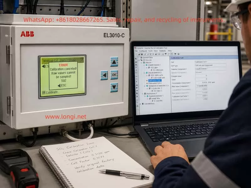
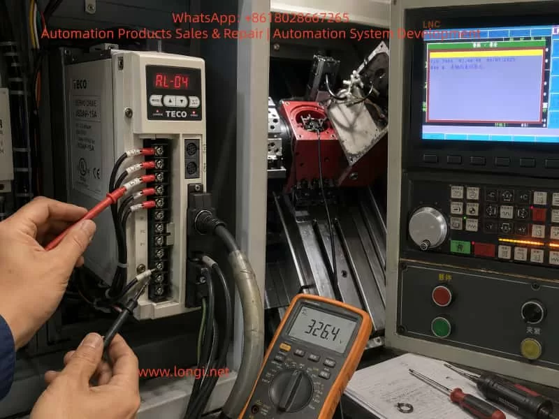
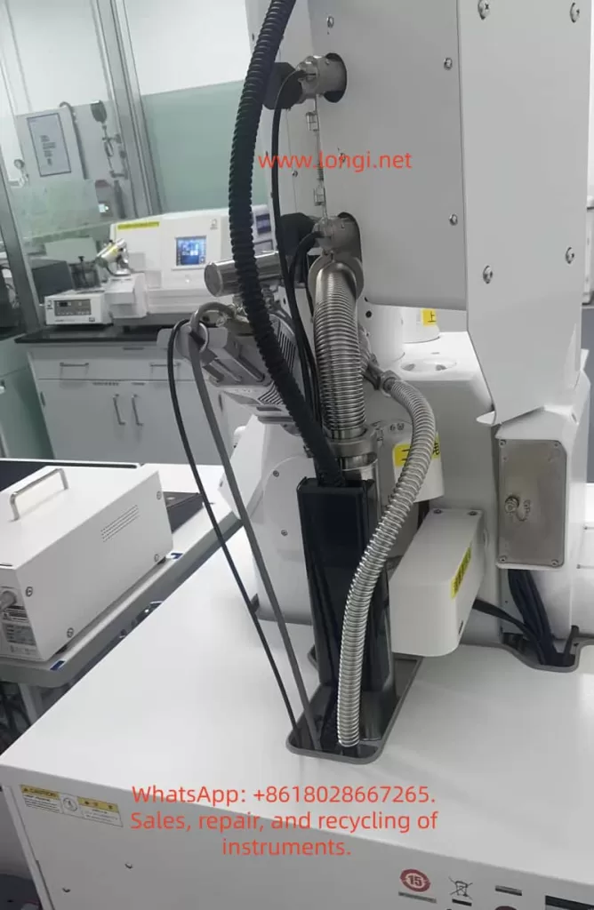
In CNC machine tools, turret mechanisms, feeder axes, clamping axes, and automated special-purpose machines, servo systems are responsible for precise positioning, fast response, and closed-loop control. Compared with a standard inverter driving an induction motor, a servo system has much higher requirements for motor power wiring, encoder feedback wiring, parameter matching, mechanical load condition, and control sequence. Once any of these links becomes abnormal, the servo drive may not merely show unstable speed or positioning deviation. Instead, it may directly trigger protective alarms such as overcurrent, encoder fault, overload, or excessive position deviation.

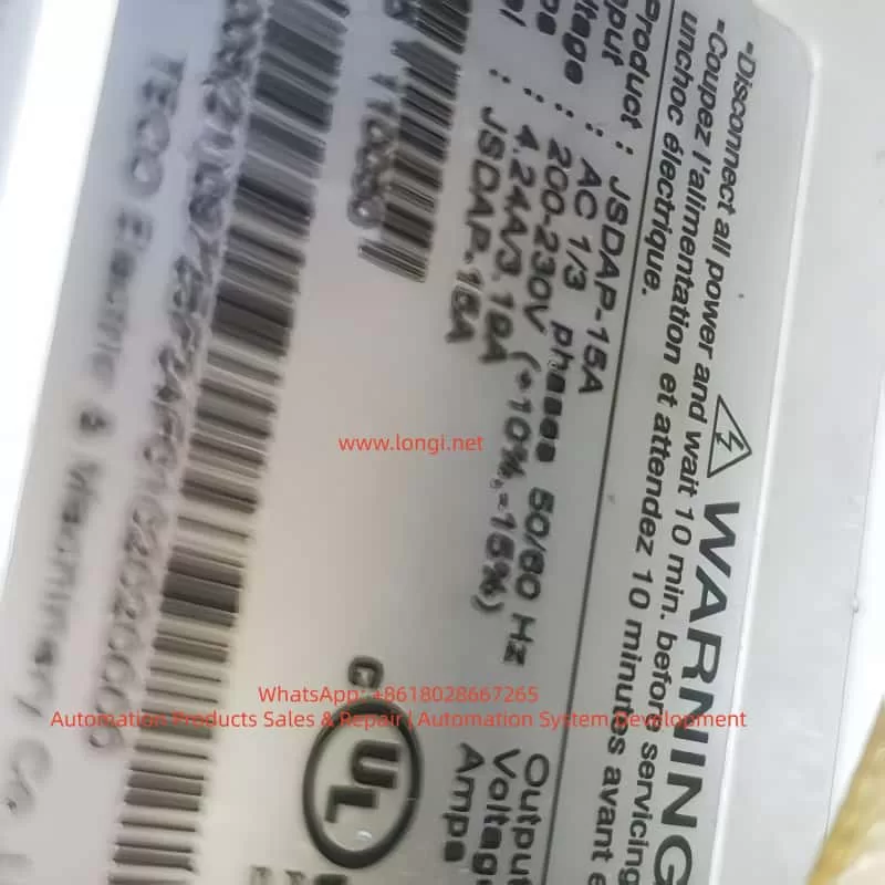
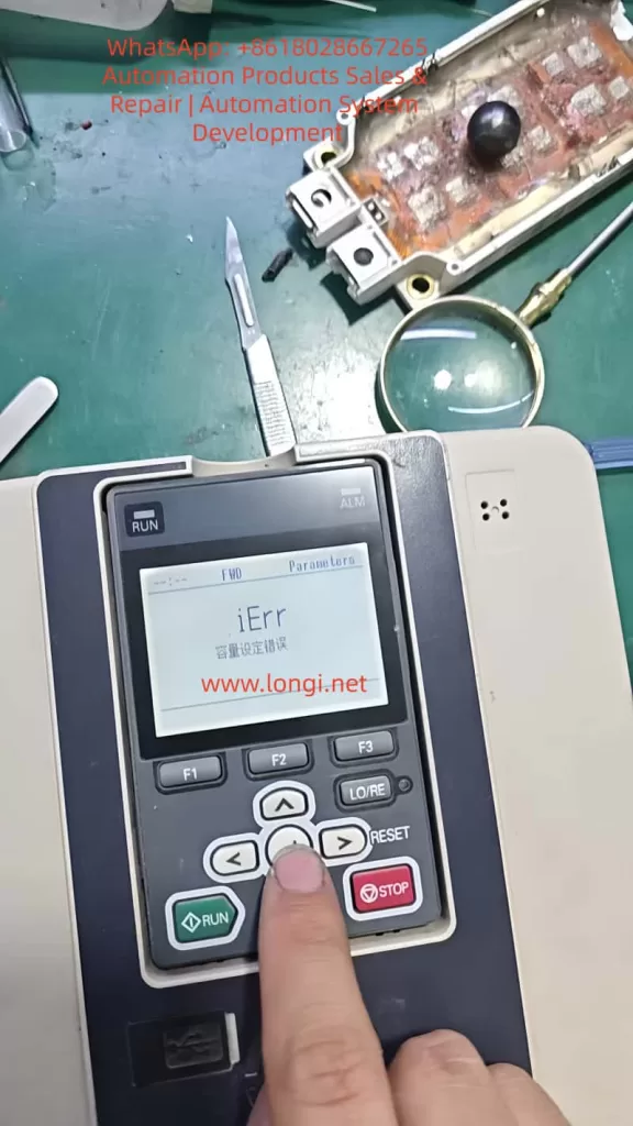
In the TECO JSDAP series servo drive, one common field alarm is RL-04, AL-04, or simply 04 on the keypad display. In actual repair work, many users tend to interpret this alarm as “high motor current” or “heavy load.” However, from a maintenance perspective, alarm 04 should not be treated as a simple overload. It is closer to an instantaneous abnormal current protection in the main power circuit. Possible causes include incorrect U/V/W motor phase wiring, abnormal encoder feedback, servo motor winding defects, damaged drive power module, mismatch between parameter Cn030 and the actual motor, mechanical jamming, or a brake that has not been released.

When a machine-tool customer reports that “the servo motor should normally rotate two turns, but now it only moves briefly and then reports RL-04 overcurrent,” this symptom has strong diagnostic value. It usually means the system is not completely faulty at power-on. Instead, the alarm occurs when the servo is enabled, the drive begins outputting current, and the motor just starts to respond. The diagnostic focus should therefore be placed on why the current rises abnormally at the moment of operation, rather than only looking at the auxiliary alarm displayed on the CNC screen.

TECO JSDAP-15A servo drive showing an RL-04 overcurrent alarm during CNC machine troubleshooting, with visible drive label, wiring terminals, technician test probes, and LNC control panel in the background.

1. Basic Meaning of the TECO JSDAP RL-04 Alarm

On the TECO JSDAP series servo drive, alarm 04 generally corresponds to drive overcurrent. From the drive’s protection logic, overcurrent does not simply mean that the load is slightly higher than usual. It means that the main circuit has detected current exceeding the protection threshold. To protect the IGBT/IPM power module, motor windings, and mechanical system, the drive immediately cuts off output and issues an alarm.

For alarm 04, the diagnostic direction normally includes checking whether the motor-side U, V, W wiring and encoder wiring are normal, and confirming that the wiring follows the standard connection diagram. If the alarm still exists after the power has been turned off for a period and then reapplied, the fault may involve the internal power transistor module of the servo drive or severe electrical noise interference.

This means RL-04/04 is not caused by one single fixed fault. It is a protective result for a class of abnormal output-current conditions. Maintenance personnel must judge the cause together with the timing of the alarm: whether it appears immediately after power-on, after servo enable, after the motor moves briefly, after a period of running, under mechanical load, or even when the motor is disconnected. Different timing points correspond to completely different fault ranges.

2. Why “The Motor Moves Once and Then Reports 04” Is Important

In field service, customers often describe the problem as “the servo motor moves a little and then alarms,” “normally it should rotate two turns, but now it stops immediately,” or “after reset, the same thing happens again.” This simple description actually contains several important clues.

First, the drive is not completely unable to power up. If the drive reports 04 immediately after control power or main power is applied, the first suspects would be the drive power module, current detection circuit, main-circuit short circuit, or serious internal component failure. In this case, however, the alarm occurs after operation begins, which means the drive can at least complete part of its initialization. The fault is triggered during output.

Second, the motor has made a short movement. If the motor can move briefly, it means the main circuit has probably output three-phase current, and the servo enable signal and part of the control logic are present. But when the motor starts and the alarm immediately appears, it suggests that the drive detects an abnormal closed-loop control condition. The current response may be much higher than expected, or the motor feedback may not match the drive output, causing the servo amplifier to increase current sharply before tripping.

Third, if the motor should normally complete two revolutions but now cannot, the axis may be involved in homing, turret indexing, clamping-axis positioning, or a fixed travel sequence. If the CNC screen also displays a message such as “clamping axis not returned to home,” that CNC message may not be the root cause. It may simply be the interlock result after the servo axis fails to complete its action. The true primary fault should still be judged from the servo drive display.

Therefore, “one brief movement followed by RL-04” should not be directly judged as motor failure, nor should it immediately be judged as drive failure. The correct approach is to distinguish mechanical load problems, motor feedback problems, power wiring problems, parameter mismatch, and drive hardware failure.

3. Common Cause 1: Incorrect, Loose, or Poorly Insulated U/V/W Motor Wiring

The U, V, W three-phase power wires of a servo motor cannot be swapped casually like those of a standard induction motor. For an ordinary three-phase induction motor, swapping any two phases mainly changes the rotation direction. But an AC servo system is closed-loop controlled. The current vector output by the drive must strictly correspond to the rotor position feedback from the encoder. If the U/V/W phase sequence is wrong, or if one phase is loose or intermittently connected, the drive may find that the motor feedback direction, speed, or phase does not match the expected response. It may then rapidly increase current to correct the error, eventually causing overcurrent protection.

In real field cases, U/V/W problems commonly occur in the following situations:

The motor or drive has been removed for repair, and the wiring was restored without a reference photo.

The terminal screws are aged or not tightened, and vibration causes poor contact during operation.

The motor cable has been worn by the drag chain, sheet-metal edge, or oil-contaminated area, damaging the insulation.

The motor connector has oil or water ingress, causing leakage or short circuits between pins.

The motor cable was replaced, but the wire colors do not match the original factory definition.

The drive output cables are bundled together with other strong-current cables, causing interference or insulation damage.

For field maintenance, wire color alone should not be used as the final judgment. The motor nameplate, connector pinout, original wiring diagram, and actual terminal marks must all be compared. After power-off and full discharge, check whether U, V, and W correspond correctly from the drive to the motor. Then measure the resistance of U-V, V-W, and W-U with a multimeter. The three values should be basically balanced. Next, measure insulation from U/V/W to the motor frame or ground. A standard multimeter can only detect serious short circuits. If insulation degradation is suspected, a megohmmeter should be used. In servo motors, insulation problems may not appear as a complete static short circuit, but may become obvious only when the drive outputs PWM voltage.

JSDAP-15A

4. Common Cause 2: Abnormal Encoder Feedback

The core of a servo system is closed-loop control. The drive not only outputs three-phase current to the motor, but also reads encoder feedback in real time to determine rotor position, speed, and direction. If encoder feedback is lost, reversed, distorted, intermittent, or affected by broken wires or poor connector contact, the drive’s judgment of motor status becomes unreliable.

Encoder faults do not always immediately appear as a dedicated encoder alarm. In some cases, the encoder signal seems normal while stationary, but once the motor starts, vibration causes an internally broken conductor to lose contact, or the feedback position jumps. The drive may then output abnormal current and finally show overcurrent protection. In machine-tool environments, oil mist, coolant, metal chips, long-term vibration, and repeated drag-chain bending can all cause hidden encoder cable damage.

Encoder troubleshooting should be performed systematically. First, power off and unplug the encoder connector. Check whether the pins are bent, retracted, oxidized, or contaminated by oil. Second, inspect the cable sheath for crushing, pulling, or excessive bending. Third, check whether the encoder power supply is normal. Many systems use 5 V encoder power, but the actual value should be confirmed according to the motor and manual. Fourth, if a same-model motor or cable is available, cross-substitution is the most effective method. Encoder cables are one of the most easily overlooked but most common fault points in field service.

If the motor is separated from the mechanical load and still shakes, rushes briefly, or reports 04 as soon as it is enabled, while U/V/W wiring shows no obvious short circuit, encoder feedback should be placed very high on the suspect list.

5. Common Cause 3: Mechanical Jamming, Brake Not Released, or Clamping Mechanism Not Open

In machine tools, a servo motor often does not drive a light free-running load. It may be connected through a coupling, timing belt, reducer, ballscrew, turret, clamping mechanism, homing mechanism, or other mechanical transmission. If the mechanical side is not fully released, the servo motor may face a near-stall load at startup. The current rises instantly, and the drive may report RL-04.

The word “no-load rotation” must be clarified. Customers may use it in two different ways. One means the motor is physically disconnected from the machine and the motor shaft is truly unloaded. The other simply means the machine is running an “empty cycle” or homing program, while the motor is still connected to the mechanical structure. These two meanings are completely different for diagnosis.

If the motor remains connected to the mechanism, the following problems may cause overcurrent:

The mechanical brake has not released.

The turret clamping mechanism has not opened.

Hydraulic or pneumatic pressure is insufficient, so unclamping is incomplete.

The reducer is internally damaged or jammed.

The ballscrew, bearing, or guideway resistance is too high.

The coupling is eccentric, over-tightened, or deformed during installation.

The home switch or limit switch state is incorrect, causing the axis to drive into a mechanical stop.

The machine has been idle for a long time, and oil sludge, chips, or dried coolant has blocked the mechanism.

For servo motors with mechanical brakes, the brake power supply must be checked carefully. A brake usually requires an external DC 24 V control supply to release. The brake wires must not be mistaken for ordinary signal wires. If the brake is not released, the motor is effectively starting against a locked rotor, and overcurrent is almost unavoidable.

The most effective way to identify a mechanical problem is to disconnect the coupling, timing belt, or reducer and let the motor truly run without load. If the motor runs normally after being disconnected and no longer reports 04, the drive and motor are probably not the main cause. The fault should be traced to the mechanical side. If the motor is completely disconnected and still reports 04 immediately after movement, the mechanical side can largely be excluded, and the electrical system should be checked first.

6. Common Cause 4: Incorrect Cn030 Motor Matching Parameter

The TECO JSDAP series drive cannot run any motor arbitrarily. The drive must know the connected motor’s power, rated current, rated speed, encoder type, inertia class, and related characteristics. The parameter Cn030 is used for the motor/drive series matching setting. The diagnostic item dn-08 can be used to check the currently configured drive and motor combination. If the displayed combination does not match the actual motor, Cn030 must be corrected.

This point is especially important for second-hand machine tools, old equipment repair, drive replacement, and parameter initialization. Many field failures are not caused by damaged hardware, but by a mismatch between the drive parameters and the actual motor. For example, the drive may be a JSDAP-15A, but the connected motor may have a different encoder type, rated current, or power class. If Cn030 is set for another motor combination, the drive’s understanding of motor electrical angle, rated current, and feedback resolution will be wrong. The result may be vibration, abnormal movement, or overcurrent immediately after operation.

Parameter mismatch is common in the following situations:

The drive has been replaced, but the original parameters were not imported.

The drive was repaired and reset to default parameters.

A used drive was installed as a substitute, with similar appearance but wrong parameter settings.

The motor was replaced, but the old drive parameters were retained.

Only part of the motion parameters was restored, while the motor-series parameter was ignored.

Different JSDAP capacity ranges or encoder specifications were mixed incorrectly.

Therefore, when troubleshooting RL-04, hardware measurement alone is not enough. The drive’s diagnostic item dn-08 should be checked and compared with the actual motor nameplate. If the motor model, power, speed, or encoder specification does not match the drive setting, Cn030 must be corrected before trial operation. Repeated testing under wrong parameter conditions not only fails to solve the problem, but may also expand the damage.

7. Common Cause 5: Servo Motor Failure

Servo motor failure can also trigger RL-04. Common motor faults include winding turn-to-turn short circuit, three-phase imbalance, insulation breakdown to ground, encoder internal failure, bearing seizure, rotor demagnetization, or brake mechanism failure.

Turn-to-turn short circuit is a relatively hidden fault. It may not show as a complete U/V/W short circuit. When measured with a standard multimeter, one phase resistance may only be slightly different, or the difference may not be obvious. However, once the drive outputs PWM current, the shorted turns generate abnormal current and heat, causing the drive to trip on overcurrent. Motors that have overheated, been contaminated by oil or water, or suffered insulation aging are more likely to develop this fault.

Insulation degradation to ground is also common. In machine-tool environments, coolant, oil mist, and metal powder can enter the motor connector or junction area, causing leakage to ground. Servo drives are sensitive to output-side leakage and current abnormalities. When leakage current becomes large, the drive may report 04 or another main-circuit alarm.

Motor bearing seizure should not be ignored either. If the motor shaft feels tight, has periodic sticking points, produces abnormal noise, or feels as though it is scraping internally, the bearing, brake, or internal mechanical structure may be damaged. A motor with a brake cannot be rotated normally unless the brake is released, so the brake-release condition must be confirmed before judgment.

For the motor itself, the most effective method is still cross-substitution. If a same-model normal motor is available, install the original motor on a known-good axis, or connect a known-good motor to the faulty drive. If the fault follows the motor, the motor or encoder is confirmed as the likely cause. If the fault remains with the original drive or original machine axis, continue checking the drive, cable, and mechanical load.

8. Common Cause 6: Drive Power Module or Current Detection Circuit Failure

If the motor, cable, encoder, parameters, and mechanical load have all been excluded, the drive itself must be considered. The power module inside the JSDAP servo drive converts the DC bus voltage into three-phase output current for the servo motor. If the IGBT/IPM module is aged, partially shorted, or if the gate drive circuit or current detection circuit is abnormal, alarm 04 may appear during operation.

Drive hardware failure often appears in the following ways:

The drive reports 04 even when the motor is disconnected.

Any connected motor causes the same 04 alarm.

The drive runs briefly when cold but frequently reports 04 after warming up.

The output three-phase current is obviously unbalanced.

The motor produces abnormal squealing or vibration before alarm.

There is a burnt smell, visible explosion mark, heavy oil contamination, or dust accumulation inside the drive.

The power module shows abnormal readings in diode-mode testing.

After power-off and full discharge, an experienced technician may perform a preliminary diode-mode check between U/V/W and the DC bus points. However, this type of inspection must be done by qualified personnel. A servo drive contains high-voltage capacitors, and dangerous voltage may remain after power is turned off. Touching internal circuits before the charge indicator is off is unsafe.

If the drive power module is confirmed to be damaged, parameter reset or external cable replacement will not solve the problem. The drive must be inspected internally, including the IPM/IGBT, gate drive optocouplers, current sensors, DC bus capacitors, snubber circuit, power supply board, and control board. For old machine tools, the external motor and cables should also be checked for the original cause. Otherwise, the repaired drive may fail again after installation.

9. Correct On-Site Troubleshooting Sequence

For alarms like RL-04, the diagnostic sequence is very important. If the drive is removed and repaired immediately, time may be wasted. If the mechanical system is jammed and the operator repeatedly resets and retries the machine, the drive power module may be damaged. A reasonable diagnostic procedure is as follows.

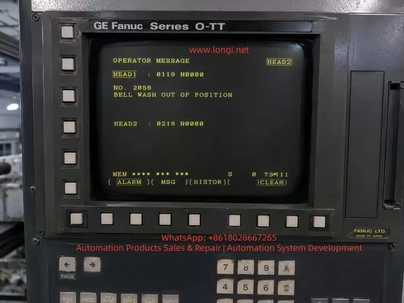
First, confirm the true alarm source. CNC screen messages such as “clamping axis not returned to home,” “servo abnormal,” or “axis not ready” are often system interlock messages, not necessarily the root cause. A clear photo of the servo drive display must be taken to confirm whether the alarm is 04, AL-04, or RL-04.

Second, observe the alarm timing. If the alarm appears immediately after power-on, suspect the drive body, main-circuit short circuit, or serious wiring error first. If it appears after servo enable, focus on motor wiring, encoder wiring, and parameters. If it appears only at a fixed mechanical position, mechanical jamming, limit status, clamping mechanism, and program sequence become more suspicious.

Third, disconnect the mechanical load. Separate the motor from the coupling, timing belt, or reducer so the motor can truly run unloaded. If it runs normally unloaded, the mechanical side is the priority. If it still alarms unloaded, the electrical side is the priority.

Fourth, check U/V/W and encoder wiring. Confirm phase order, terminal tightness, connector condition, shielding, grounding, insulation, and possible internal cable breakage. Pay special attention to drag-chain cables and oil-contaminated connectors.

Fifth, check Cn030 and dn-08. Confirm whether the drive model, motor model, power, speed, and encoder specification match. This step is essential for second-hand machines and machines whose drives have been replaced or repaired.

Sixth, test the motor. Check three-phase resistance balance, insulation to ground, brake release, shaft rotation resistance, and encoder feedback condition.

Seventh, perform cross-substitution. Use a known-good same-model motor, cable, or drive for comparison. Cross-substitution is more reliable than guessing.

Eighth, evaluate drive hardware. If the drive reports 04 without the motor connected, or if the same alarm remains after replacing the motor and cable, the drive should enter the internal repair process.

10. Analysis of the CNC “Clamping Axis Not Returned to Home” Message

On some CNC lathes or special-purpose machines, the servo axis may not be a standard X/Z feed axis. It may be used for a clamping axis, turret, indexing table, feeder mechanism, or auxiliary homing mechanism. When the CNC screen displays “clamping axis not returned to home,” this does not necessarily mean the home switch is faulty. It may mean the servo axis reported RL-04 immediately after starting during the homing process, so the PLC never received the home-complete signal.

In this situation, the fault chain should be divided into two layers.

The lower-level fault is the servo drive 04 overcurrent alarm.
The upper-level fault is the CNC/PLC message caused by the servo axis failing to complete the required motion.

If only the upper-level alarm is handled, such as replacing the home switch, changing the PLC input, or forcing home completion, the real problem may remain. The correct method is to make the servo axis run stably first, then handle the homing logic. For clamping, unclamping, turret positioning, and similar mechanisms, pneumatic or hydraulic signals are often required before servo movement. If the unclamp signal is not complete and the servo axis is forced to move, the motor is effectively starting against a mechanical lock, so overcurrent is a reasonable result.

For JSDAP servo alarms on clamping-axis or turret mechanisms, the following items should be checked at the same time:

Whether the unclamping solenoid valve operates.

Whether air pressure or hydraulic pressure meets the required level.

Whether the clamped and unclamped position switches provide correct feedback.

Whether the mechanical lock pin has fully retracted.

Whether the homing direction is correct.

Whether the servo enable sequence occurs after unclamping is completed.

Whether an abnormal PLC input causes the servo to start under the wrong condition.

11. Maintenance Precautions

When dealing with RL-04, frequent reset and forced operation are not recommended. Every overcurrent trip stresses the power module, motor winding, and DC bus capacitors. If the actual fault is U/V/W short circuit, unreleased brake, or mechanical jamming, repeated trial operation can turn a repairable minor fault into a damaged power module.

U/V/W should also not be swapped casually to “test direction.” In a servo system, direction should be corrected through parameters, command settings, or proper motor matching, not by randomly swapping output phases like an induction motor. Incorrect phase sequence may cause closed-loop runaway and instantaneous current shock.

Encoder wiring must not be modified randomly either. Encoder feedback is a low-voltage high-speed signal. It should use proper shielded cable and be routed away from power wiring. Shield grounding should follow the original design. Multiple random grounding points can create interference loops. If the encoder cable has been soaked in oil or repeatedly bent in the drag chain, replacing the cable is often more effective than merely cleaning the connector.

For old machine tools, the cabinet environment also matters. Oil mist, metal dust, poor heat dissipation, fan failure, poor grounding, supply voltage fluctuation, and strong electrical interference can all reduce servo system stability. The drive should be installed in an environment with proper ventilation, limited dust and oil mist, reliable grounding, and sufficient heat dissipation.

12. Conclusion

The TECO JSDAP servo drive RL-04 or 04 alarm is essentially a drive overcurrent protection. It may be caused by a damaged drive power module, but in machine-tool field service, more common causes include abnormal U/V/W motor power wiring, encoder feedback problems, mechanical jamming, unreleased brake, clamping mechanism not open, or mismatch between parameter Cn030 and the actual motor.

For the symptom “the servo motor only moves briefly and then reports RL-04, while it should normally rotate two turns,” the most important diagnostic method is to disconnect the motor from the mechanical load and perform a true no-load test. If the motor runs normally after being disconnected, focus on the mechanical lock, brake, reducer, turret, or clamping-axis mechanism. If it still reports 04 when disconnected, focus on U/V/W wiring, encoder cable, motor body, Cn030/dn-08 matching, and drive hardware.

When repairing this type of fault, do not rely only on the CNC screen message, and do not immediately assume the drive is damaged. The correct procedure is: confirm the alarm source, observe the alarm timing, disconnect the mechanical load, check power wiring, check encoder feedback, verify parameters, test the motor, perform cross-substitution, and then repair the drive if necessary. This sequence reduces misjudgment, lowers unnecessary replacement cost, and prevents repeated trial operation from expanding the fault.

In actual machine-tool maintenance, RL-04 is not an isolated alarm. It is the protective result of interaction among the servo drive, motor, cable, mechanical structure, and PLC sequence. Only by analyzing it as a complete system can the real cause be found.

Posted on

Analysis and Repair Method for Yaskawa GA700 A1-03 Initialization Error iErr “Capacity Setting Error”

When servicing, commissioning, or restoring parameters on a Yaskawa GA700 inverter, technicians may encounter a common but easily misunderstood problem: when setting A1-03 = 2220 to perform 2-wire sequence initialization, the keypad does not complete initialization and instead displays iErr, meaning capacity setting error.

This error is often misjudged as a wrong key operation, insufficient access level, keypad failure, or corrupted software. In reality, for the GA700 series, the key issue is usually not A1-03 itself, but a mismatch between the inverter’s internal capacity setting and the actual power unit.

Yaskawa GA700 control boards have a certain level of interchangeability. In repair work, a control board may be taken from another GA700 unit and installed onto a different power section. However, “physically compatible” does not mean “automatically matched.” The control board must know the correct inverter capacity. If the capacity code stored in the control board does not match the actual power unit, the inverter may power up and display normally, but initialization, auto-tuning, or operation may fail.

iErr fault of the GA700 Inverter

1. What A1-03 = 2220 Actually Does

In GA700 parameters, A1-03 is the initialization parameter.

Common settings include:

1110: Initialize using user-saved parameters.
2220: 2-wire sequence initialization.
3330: 3-wire sequence initialization.

When A1-03 = 2220 is executed, the inverter restores many parameters to factory settings and assigns terminals S1 and S2 as forward run and reverse run inputs. However, this does not mean every parameter is reset. Several fundamental parameters are excluded from normal initialization, including capacity-related settings such as o2-04.

The important point is that “factory setting” is not one fixed parameter set for all GA700 drives. A 5.5 kW inverter, a 15 kW inverter, a 22 kW inverter, and a 75 kW inverter cannot share the same rated current, carrier frequency limit, overload curve, motor default values, or protection settings. Therefore, before the inverter can restore factory settings, it must first know its correct model and capacity.

If the capacity information is wrong, initialization cannot be safely completed.

2. The Real Meaning of iErr Capacity Setting Error

The iErr message is not a normal running fault such as overcurrent, overvoltage, undervoltage, or overload. It is closer to a parameter-processing error caused by failed capacity verification.

In simple terms, the inverter detects that:

the control board thinks it belongs to one capacity,
but the actual power unit appears to be another capacity,
or the capacity selection parameter has not been correctly written.

As a result, the inverter cannot safely generate the correct factory parameter set, so it refuses to complete initialization and displays iErr.

This protection logic is reasonable. If the inverter uses the wrong capacity data, it may apply the wrong rated current, wrong overload protection, wrong module thermal protection, wrong carrier frequency limit, and wrong control gain. The result may range from poor performance to IGBT damage, driver board damage, current detection errors, or motor damage.

The key parameter is:

o2-04 — Inverter Capacity Selection

This parameter sets the inverter model/capacity. After replacing the control circuit board, o2-04 must be correctly set according to the actual inverter model. If o2-04 is wrong, the protection functions may not operate correctly, and the inverter may be damaged.

Therefore, when A1-03 = 2220 causes iErr, the first parameter to check is not A1-03, but o2-04.

3. Why This Happens After Replacing the Main Control Board

Many technicians know that Yaskawa inverter control boards are often partly universal within the same series. This is true, but it must not be misunderstood.

The correct understanding is:

The control board may be hardware-compatible, but its capacity setting must match the actual power unit.

A GA700 inverter’s identity is determined by several items together:

  1. Nameplate model;
  2. Input voltage class;
  3. Rated output current;
  4. Power unit specification;
  5. Control board software version;
  6. o2-04 inverter capacity selection;
  7. C6-01 heavy-duty/light-duty selection;
  8. Capacity-dependent factory parameters.

If a control board is replaced but o2-04 is not corrected, the inverter may still power up, enter menus, and accept some parameter changes. However, problems may appear during initialization, auto-tuning, or trial operation. iErr during A1-03=2220 is a typical symptom.

4. o2-04 Is the Core Parameter

o2-04 is not a motor power parameter. It is not a parameter where the technician simply enters a motor kW value. It is a capacity selection code corresponding to the actual GA700 inverter model.

For example, for common 400 V class GA700 models:

Inverter Model Suffixo2-04 Setting
400292
400493
400594
400795
400996
401297
401899
40239A
40319C
40389D
40449E
40609F
4075A1
4089A2
4103A3
4140A4
4168A5
4208A6
4250A7
4296A8
4371A9
4389AA
4453AC
4568AD
4675AE
4810B0
4930B1
4H11B2
4H12B3

For example:

CIPR-GA70B4031o2-04 = 9C
CIPR-GA70B4060o2-04 = 9F
CIPR-GA70B4018o2-04 = 99

This value must be selected according to the inverter nameplate model, not according to the motor power at the site.

CIPR-GA70B4002ABBA-AAAAAA

5. What Happens If o2-04 Is Set Incorrectly

Some people think the capacity parameter only affects the displayed model or rated power. This is dangerous.

An incorrect o2-04 setting may affect:

Rated Current Judgment

The drive’s overload protection, electronic thermal protection, and current limit are based on the correct inverter rated current. If a 15 kW inverter is set as a 7.5 kW unit, it may trip too early. If a 7.5 kW inverter is set as a 15 kW unit, protection may become too slow, and the power module may be damaged.

Carrier Frequency Limit

Different capacity drives have different allowable carrier frequency ranges. Larger drives generate more heat, and an excessive carrier frequency may cause the IGBTs to overheat.

Motor Default Parameters

After initialization, motor rated capacity, motor rated current, V/f base values, and other defaults may depend on the inverter capacity.

Protection Curves

Overload, overheat, module protection, and braking protection are all related to capacity. A wrong capacity setting may make protection inaccurate.

Control Performance

Vector control, current loop response, speed loop response, torque response, and low-speed performance all require correct capacity-based settings. If the capacity is wrong, the drive may still run, but it may show poor torque, vibration, overcurrent, unstable speed, or acceleration failure.

6. Correct Field Repair Procedure

When A1-03=2220 displays iErr, follow this procedure.

Step 1: Stop Repeating Initialization

Do not keep entering A1-03=2220. If the capacity data is wrong, repeating the same operation will not solve the problem.

Step 2: Check the Inverter Nameplate

Record the complete model number, especially:

  1. Full inverter model;
  2. Voltage class;
  3. Rated output current;
  4. Rated power;
  5. Production information;
  6. Whether it is a special version.

Example:

CIPR-GA70B4031xxxx

The key section is 4031.

Step 3: Set Parameter Access Level

Set:

A1-01 = 2

This allows access to advanced parameters. If the access level is too low, some parameters may not be visible or editable.

Step 4: Check Current o2-04

Enter parameter o2-04 and check whether the displayed value matches the nameplate model suffix.

Examples:

GA70B4018o2-04 = 99
GA70B4023o2-04 = 9A
GA70B4031o2-04 = 9C
GA70B4038o2-04 = 9D
GA70B4060o2-04 = 9F

If the value is obviously different, this is very likely the cause of iErr.

Step 5: Correct o2-04

Set o2-04 according to the actual inverter model.

After changing o2-04, power off the inverter. Wait until the CHARGE indicator is completely off and the DC bus voltage has dropped to a safe level. Then power on again.

This restart allows the drive to reload capacity-related internal settings.

Step 6: Execute A1-03 = 2220 Again

After power cycling, set:

A1-03 = 2220

If the capacity setting was the cause, initialization should now complete normally.

After initialization, recheck:

  1. A1-02 control method;
  2. C6-01 heavy-duty/light-duty selection;
  3. Motor rated voltage;
  4. Motor rated current;
  5. Motor rated frequency;
  6. Motor rated speed;
  7. Run command source;
  8. Frequency reference source;
  9. Acceleration/deceleration time;
  10. Multi-function terminal settings.

Do not assume that the drive is ready for load operation immediately after initialization. Application parameters must still be set correctly.

7. If iErr Still Appears After Correcting o2-04

If o2-04 matches the nameplate but A1-03=2220 still causes iErr, check deeper hardware and data issues.

Control Board and Power Board Version Mismatch

The control board may not be suitable for this voltage class, capacity range, or hardware version. Similar appearance does not guarantee compatibility.

Power Board Identification Circuit Problem

Some drives read capacity-related information from the power section, driver board, or internal identification circuit. Check:

  1. Control board-to-driver board ribbon cable;
  2. Connector oxidation;
  3. Bent pins;
  4. Loose or reversed cable connection;
  5. Low-voltage supply on the driver board;
  6. Identification resistors or related circuits.

EEPROM or Parameter Memory Error

If the drive has been affected by water, lightning, abnormal control power, failed repair, or incorrect programming, parameter memory may be corrupted. In this case, keypad operation may not be enough. The unit may require engineering software, special tools, EEPROM repair, or control board replacement.

Unknown Second-Hand Assembly

Used drives may be assembled from different units. The outer nameplate, control board, power board, and keypad may not belong to the same original inverter. In such cases, the technician must identify the actual power section rather than blindly trusting the nameplate.

Incorrect Capacity Code Entry

o2-04 values are not simple decimal numbers. Codes such as 9A, 9C, 9F, and A1 must be entered exactly. Misreading or mistyping these values will continue to cause problems.

8. Example Case

Suppose the nameplate shows:

CIPR-GA70B4031

This is a 400 V class GA700 with model suffix 4031. The corresponding o2-04 setting is 9C.

If a technician installs a control board taken from a GA70B4060, that control board may still store o2-04 = 9F. The drive may power on normally, but when A1-03=2220 is executed, it displays iErr.

The correct repair is:

  1. Set A1-01 = 2;
  2. Set o2-04 = 9C;
  3. Power off and wait until the CHARGE light goes out;
  4. Power on again;
  5. Set A1-03 = 2220;
  6. Reconfigure motor and application parameters.

If the initialization succeeds after this procedure, the original problem was capacity mismatch.

9. Common Mistakes to Avoid

Do not set o2-04 to a larger capacity just to avoid overload trips. This may delay protection and damage the inverter.

Do not set o2-04 according to motor power. It must be set according to the inverter’s actual model and power unit.

Do not assume initialization can fix capacity mismatch. Initialization itself depends on correct capacity data.

Do not skip power cycling after changing o2-04.

Do not ignore C6-01. Heavy-duty/light-duty selection affects rated current and overload characteristics.

10. Trial Operation After Repair

After correcting the capacity setting and completing initialization, perform a staged test.

First, power on the drive without load. Confirm that there is no fault, the keypad displays normally, the fan works normally, DC bus voltage is normal, and there is no abnormal smell or noise.

Second, check basic parameters, including:

A1-02 control method;
b1-01 frequency reference source;
b1-02 run command source;
C1-01 acceleration time;
C1-02 deceleration time;
E1-01 input voltage setting;
E1-04 maximum output frequency;
E2-01 motor rated current;
C6-01 heavy-duty/light-duty selection.

Third, run the motor without mechanical load at low frequency, such as 5 Hz, 10 Hz, and 20 Hz. Observe output current balance, motor rotation direction, vibration, and any abnormal alarm.

Fourth, gradually apply load. Do not immediately start with full load.

Fifth, perform motor auto-tuning if vector control or high-performance operation is required.

11. Professional Explanation for Customers

A clear explanation to the customer can be:

When the Yaskawa GA700 displays iErr during A1-03=2220 initialization, it indicates a capacity setting error. This is usually not caused by incorrect keypad operation or by the initialization command itself. The more likely cause is that the control board’s inverter capacity selection does not match the actual power unit. Although the GA700 control board has some interchangeability, after replacing the control board, parameter o2-04 must be set according to the actual inverter model. If the capacity setting is wrong, the drive cannot safely generate the correct factory parameter set, so it refuses initialization and displays iErr. The correct repair is to verify the nameplate model, set the proper o2-04 capacity code, power cycle the drive, and then execute A1-03=2220 again.

12. Conclusion

When a Yaskawa GA700 inverter reports iErr while setting A1-03=2220, the key point is not the initialization command itself but the inverter capacity selection parameter o2-04.

The GA700 control board may be reusable across certain models, but it must be matched to the actual power unit through the correct capacity code. If o2-04 is wrong, the inverter cannot safely restore factory parameters and will report a capacity setting error.

The correct repair logic is:

Check the inverter nameplate,
identify the model suffix,
set the correct o2-04,
power cycle the inverter,
execute A1-03=2220,
then reconfigure motor parameters and perform trial operation.

This fault looks like an initialization failure, but its real cause is usually a mismatch between the control board identity and the actual power unit capacity. For used GA700 drives, repaired units, replaced control boards, and mixed assemblies, this point is especially important.

Posted on

Troubleshooting Vacuum System Faults on a JEOL JSM-IT700HR/LA Scanning Electron Microscope: From EVAC Failure to Successful Recovery

1. Background: When an SEM Cannot Work, the Electron Gun Is Not Always the Problem

A scanning electron microscope is a precision analytical instrument that depends heavily on a stable vacuum environment. For a field emission SEM such as the JEOL JSM-IT700HR/LA, the vacuum system is not just an auxiliary subsystem. It is one of the fundamental conditions that determines whether the instrument can enter observation mode.

When users report problems such as “the SEM cannot work,” “the software remains on the vacuum page,” “the system cannot enter observation,” or “there is no image,” the first suspicion is often directed toward the electron gun, high-voltage system, main computer, detector, or EDS analysis system. In many real service cases, however, the root cause is not located in the electron optical system. It is often related to the sample chamber, vacuum pump, vacuum valve, compressed air supply, vacuum sensor, or vacuum interlock logic.

This article discusses a real troubleshooting case involving a JEOL JSM-IT700HR/LA analytical field emission scanning electron microscope. The customer provided several photos of the instrument and a video of the fault condition. The instrument software was stopped on the Vacuum System page, and the customer repeatedly pointed to a rear-side module related to the vacuum system. Based on the visual evidence and operating condition, the initial diagnosis was that the SEM had failed to complete the normal EVAC sequence, preventing the system from entering Observation mode.

After the customer followed a low-risk troubleshooting procedure involving the sample chamber door, O-ring, air supply, EVAC/VENT status, pump operation, and valve action, the instrument resumed normal operation. This confirmed that the fault was not a serious failure of the electron gun, EDS, display, or computer system. It was a typical vacuum interlock or vacuum sequence issue.


Technician troubleshooting a JEOL JSM-IT700HR scanning electron microscope in a laboratory, with the computer monitor showing a vacuum system fault and recovery status beside the SEM workstation.

2. Instrument Overview: Why the JSM-IT700HR/LA Depends So Much on Vacuum Conditions

The JEOL JSM-IT700HR/LA is a high-performance field emission SEM with analytical capability. Compared with a conventional tungsten-filament SEM, a field emission SEM is much more sensitive to vacuum quality, especially around the electron gun, column, and sample chamber isolation system.

A typical configuration includes:

  1. Electron gun system
    This generates the electron beam. A field emission gun is highly sensitive to contamination, moisture, and poor vacuum. It should never be forced to operate when the required vacuum has not been achieved.
  2. Electron optical column
    This includes condenser lenses, objective lens, scanning coils, stigmator system, and other beam control components.
  3. Sample chamber
    This is where the user loads samples. It is also the part of the instrument that is opened and closed most frequently, making it one of the most common sources of vacuum problems.
  4. Vacuum system
    This includes the roughing pump, turbo molecular pump, ion pump, vacuum valves, vent valve, gauges, pipelines, and pneumatic actuators.
  5. Control system and software interface
    The control software displays vacuum status, pump status, valve status, alarms, beam parameters, and imaging status.
  6. EDS and analytical accessories
    The “LA” configuration generally indicates an analytical version, often with an EDS system or related analytical hardware.

The key point is this: whether the SEM can enter Observation mode does not depend only on the computer or software. It depends on whether all vacuum, pump, valve, pressure, door, and high-voltage interlock conditions are satisfied.

Therefore, when the software stays on the Vacuum System screen, the first direction should be the vacuum system rather than the electron gun or main control board.


JEOL JSM-IT700HR/LA analytical scanning electron microscope front view with sample chamber, electron column, ion pump, camera, control monitor, and labeled SEM components in a laboratory.

3. Fault Symptoms: The System Stayed on the Vacuum System Page

In this case, the video showed the SEM control interface displaying the vacuum system status diagram. Several important signs were visible:

  • The software was stopped at the Vacuum System page.
  • Status indicators such as VENT, EVAC, LV, and LLC were visible.
  • The VENT/EVAC status did not appear to be in a normal completed state.
  • Several valves, pumps, or vacuum paths appeared in abnormal colors.
  • The customer focused attention on a rear-side module with a fan and nearby control board.
  • The system could not smoothly enter normal observation mode.

These signs indicate that the fault was not simply “no image.” The SEM had not completed its vacuum preparation sequence. Before a scanning electron microscope can generate an image, the sample chamber must be evacuated from atmospheric pressure to the required vacuum level. Only after the required pressure and valve conditions are satisfied will the instrument allow the system to open the necessary valves, enable the electron beam, and enter observation mode.

Therefore, the correct diagnostic question is not:

“Why is there no SEM image?”

The correct question is:

“Why did the sample chamber or column vacuum sequence fail to complete?”

This distinction is critical. Once the fault direction is correctly limited to the vacuum system, unnecessary work on the computer, monitor, EDS system, electron gun, or detector can be avoided.


Rear-side view of a JEOL JSM-IT700HR/LA scanning electron microscope showing vacuum hoses, metal bellows, cables, pump connections, and rear vacuum system components.

4. Basic SEM Vacuum Sequence

To understand this type of fault, it is necessary to understand the normal vacuum sequence of an SEM.

A simplified operating sequence is as follows:

  1. The user presses VENT to bring the sample chamber to atmospheric pressure.
  2. The chamber reaches atmospheric pressure and the chamber door can be opened.
  3. The sample is loaded.
  4. The chamber door is closed.
  5. The user presses EVAC.
  6. The roughing pump starts to evacuate the sample chamber.
  7. The sample chamber pressure decreases.
  8. Vacuum valves switch in a defined sequence.
  9. The turbo molecular pump or high-vacuum system becomes effective.
  10. The pressure reaches the required range.
  11. The system allows Observation mode.
  12. The electron beam is enabled and imaging begins.

Every step is controlled by interlocks. The system may check:

  • Whether the sample chamber door is closed.
  • Whether the chamber is leaking.
  • Whether the O-ring is sealing correctly.
  • Whether the vent valve is fully closed.
  • Whether the EVAC valve is open.
  • Whether the roughing pump has started.
  • Whether the backing pressure is suitable for the turbo pump.
  • Whether the turbo pump has reached its required speed.
  • Whether the vacuum gauges are giving reasonable feedback.
  • Whether compressed air pressure is sufficient.
  • Whether valve position feedback is correct.
  • Whether the gun vacuum is safe for beam operation.

If any one of these conditions fails, the SEM may remain on the vacuum page and refuse to enter observation mode.

That is why an SEM vacuum fault often appears as a complete machine failure, even though the actual cause may be a small interlock condition.


JEOL JSM-IT700HR/LA field emission scanning electron microscope side view showing the electron column, ion pump, sample chamber, camera module, and laboratory gas pressure gauge.

5. Most Probable Causes in This Case

Based on the photos, the video, and the later successful recovery, the likely causes are concentrated in the following areas.

5.1 Sample Chamber Door Not Properly Sealed

The sample chamber door is one of the most common vacuum leak points in an SEM. It is opened and closed frequently, so its sealing surface and O-ring are exposed to dust, sample debris, carbon tape fragments, conductive adhesive, and mechanical wear.

Common problems include:

  • The chamber door is not fully closed.
  • The sample stage is too high and physically interferes with the chamber door.
  • A sample holder, screw, or specimen edge touches the chamber wall.
  • Dust or particles are present on the O-ring.
  • Carbon tape, powder, metal particles, or adhesive remain on the sealing surface.
  • The O-ring has cracks, compression marks, hardening, or deformation.
  • The chamber door hinge or locking mechanism is slightly misaligned.

If the sample chamber door is not pulled inward by vacuum after pressing EVAC, or if evacuation takes much longer than usual, the first component to inspect should be the chamber door seal. In many cases, cleaning the O-ring and sealing surface is enough to restore normal evacuation.

5.2 VENT Valve Not Fully Closed

The VENT valve is used to admit air or nitrogen into the chamber so that the door can be opened. If the VENT valve does not fully close, the roughing pump will continuously pull against an air leak. The chamber pressure will not decrease properly.

A VENT valve problem may show the following symptoms:

  • A slight air inlet sound after pressing EVAC.
  • Very slow pressure decrease.
  • Abnormal VENT status on the vacuum page.
  • The system recovers after repeated VENT and EVAC operations.
  • Intermittent valve sticking or poor sealing.

If the instrument recovers after repeated EVAC/VENT operation, the VENT valve or related pneumatic valve may have been sticking or not fully seated.

5.3 EVAC Valve or Pneumatic Valve Action Abnormal

The EVAC valve opens the evacuation path between the sample chamber and the pumping line. If the EVAC valve does not open, the pump may run but the chamber will not be evacuated.

Many SEM vacuum valves are not directly driven by small solenoids alone. They may use compressed air through pneumatic actuators. The control board sends an electrical signal, the solenoid valve switches, and compressed air moves the vacuum valve. If compressed air pressure is insufficient, the software may command the valve to move, but the valve may not actually reach its correct position.

Therefore, the technician should check:

  • Whether the compressed air supply is on.
  • Whether the air pressure is within the required range.
  • Whether the regulator is set correctly.
  • Whether air tubing is loose or kinked.
  • Whether the filter/regulator contains water.
  • Whether a clear valve actuation sound can be heard when pressing EVAC or VENT.
  • Whether the valve body is sticking.
  • Whether valve position feedback is correct.

Low compressed air pressure can cause slow valve motion, incomplete valve travel, inconsistent feedback, or a vacuum sequence stop.

5.4 Roughing Pump or Dry Pump Not Starting Correctly

The roughing pump is essential for bringing the sample chamber down from atmospheric pressure to a low-vacuum level. If it does not start, or if its pumping capacity is severely reduced, the chamber cannot reach the conditions required for the next stage.

Typical symptoms include:

  • No pump sound after pressing EVAC.
  • Cooling fan runs but the pump does not actually pump.
  • Pump body overheats.
  • Pump control board has no output.
  • A fuse is blown.
  • Power cable or control cable is loose.
  • The pump is worn and has reduced pumping speed.
  • The roughing line is blocked or leaking.

In the video, the customer pointed to a rear module with a fan and nearby control board. This suggests that the on-site operator already suspected a module related to the pump, power supply, valve control, or vacuum I/O. It is important to confirm whether the pump is truly operating after EVAC, not merely whether a fan is spinning.

5.5 Turbo Molecular Pump or High-Vacuum System Not Reaching Required Conditions

For a field emission SEM, the high-vacuum section can only work normally after the roughing stage reaches an acceptable pressure. If the backing pressure is too high, the turbo molecular pump may not start correctly or may fail to reach rated speed.

A turbo pump-related issue may show:

  • The roughing pump operates, but the pressure remains too high.
  • TMP speed does not reach the required value.
  • A TMP error or controller alarm appears.
  • The vacuum sequence stops halfway.
  • The system cannot enter high-vacuum mode or Observation.

However, in this case, because the instrument recovered after basic external checks, a serious turbo pump failure is less likely. A damaged turbo pump usually does not fully recover simply by cleaning the chamber seal or repeating the EVAC sequence.

5.6 Vacuum Sensor Feedback Abnormal

The vacuum control system depends on sensor feedback. If a vacuum gauge gives incorrect information, the SEM may refuse to proceed even if the actual pressure is acceptable.

Possible causes include:

  • Contaminated vacuum gauge.
  • Aging gauge.
  • Loose sensor cable.
  • Oxidized connector.
  • Control board input fault.
  • Abnormal sensor power supply.
  • Software reading error.

For this kind of issue, it is not enough to look at the color of the vacuum diagram. The actual pressure values must be recorded, including:

  • Chamber pressure.
  • Column pressure.
  • Gun pressure.
  • Turbo pump speed.
  • Ion pump current.
  • Error log.
  • Valve status.

If a pressure value does not change at all during evacuation, the sensor or its signal path should be suspected.


Close-up of the JEOL JSM-IT700HR/LA nameplate showing the model number and analytical scanning electron microscope identification label made in Japan.

6. Why the Electron Gun or Main Board Should Not Be Disassembled First

High-end field emission SEM troubleshooting must follow a safe order: from external to internal, from low risk to high risk, from interlock conditions to core hardware.

The electron gun and column should not be opened without strong evidence.

There are several reasons:

  1. The field emission gun is extremely sensitive to contamination
    Air exposure, moisture, particles, and oil vapor can cause unstable emission, low beam current, or permanent gun damage.
  2. Column disassembly requires clean conditions and calibration
    Random disassembly may introduce dust, mechanical misalignment, and vacuum contamination.
  3. Forcing beam operation under poor vacuum is risky
    Poor vacuum can cause high-voltage interlock, discharge, contamination, or emission instability.
  4. When the system is stopped at the Vacuum System page, the electron optical system may not even be active yet
    No image at this stage does not prove detector failure or electron gun failure. It may only mean that the system has not allowed beam operation.
  5. Control board potentiometers must not be adjusted randomly
    A visible trimmer or adjustable component on a control board may be used for threshold, feedback, drive calibration, or sensor adjustment. Without the service manual and original setting, it should not be turned.

Therefore, for this type of case, the correct approach is not to start with the most expensive component. The correct approach is to verify whether the most basic vacuum conditions are satisfied.


7. Recommended On-Site Troubleshooting Procedure

The following procedure can be used for SEM vacuum-related faults.

Step 1: Identify the Stage Where the Fault Occurs

The technician should first determine whether the problem occurs during:

  • VENT;
  • EVAC;
  • transition to high vacuum;
  • Observation entry;
  • beam enable;
  • imaging after the beam is already on.

Different stages correspond to different fault areas.

If the system is stuck on the Vacuum System page and cannot enter Observation, the vacuum system should be checked first.

Step 2: Observe Mechanical Response After Pressing EVAC

After pressing EVAC, observe:

  • Does the roughing pump start?
  • Is there a pump sound?
  • Is the chamber door pulled tight by vacuum?
  • Is there a valve actuation sound?
  • Does the compressed air system move any valves?
  • Does the chamber pressure decrease?
  • Does the system produce an error message?
  • Does it automatically return to VENT?

If there is no sound at all, check power, interlocks, pump control, and control signals.
If the pump runs but the door is not pulled inward, check for a large leak or EVAC valve failure.
If the door seals but the pressure decreases slowly, check for a small leak, weak pump, or leaking VENT valve.

Step 3: Inspect the Sample Chamber Seal

The recommended procedure is:

  1. Vent the chamber.
  2. Open the sample chamber.
  3. Remove the sample.
  4. Check whether the sample stage is too high.
  5. Inspect the sample holder, screws, and specimen edges.
  6. Inspect the chamber O-ring.
  7. Inspect the sealing surface.
  8. Clean the O-ring and sealing face carefully with suitable lint-free material.
  9. Close the chamber door again.
  10. Press EVAC and observe the result.

Do not use ordinary paper tissue that sheds fibers. Do not use aggressive solvent on the O-ring.

Step 4: Check the Compressed Air Supply

If the instrument uses pneumatic valves, compressed air must be checked.

Inspect:

  • Air pressure.
  • Air supply valve.
  • Regulator setting.
  • Loose air tubes.
  • Kinked tubes.
  • Water in the filter/regulator.
  • Valve actuation sound during EVAC and VENT.

Insufficient air pressure is a hidden but common cause of SEM vacuum sequence failure. It may not always appear as a direct air pressure alarm, but it can stop valves from reaching their correct position.

Step 5: Check the Roughing Pump

Inspect:

  • Whether the pump starts.
  • Whether the pump sound is normal.
  • Whether there is abnormal vibration.
  • Whether the pump is overheating.
  • Whether exhaust flow is present.
  • Whether power input is normal.
  • Whether the control cable is loose.
  • Whether the fuse is blown.
  • Whether the pipe connection is leaking.
  • Whether the pump is overdue for maintenance.

If it is an oil pump, check oil level and oil condition. If it is a dry pump, check sound, temperature, and alarm indicators.

Step 6: Record Actual Vacuum Values and Error Logs

The technician should not rely only on colors in the vacuum diagram. Actual data should be recorded:

  • Sample chamber pressure.
  • Column pressure.
  • Gun pressure.
  • Roughing pressure.
  • Turbo pump speed.
  • Ion pump current.
  • Valve status.
  • Error log.
  • Time required for evacuation.

These values help distinguish between leakage, weak pump performance, valve failure, and sensor feedback errors.

Step 7: Verify Repeatability

After recovery, the test should not stop immediately. Perform repeated cycles:

  1. VENT.
  2. Open and close the chamber.
  3. EVAC.
  4. Enter Observation.
  5. VENT again.
  6. EVAC again.
  7. Repeat at least two or three times.

If the sequence succeeds every time, the system is likely stable.
If the problem appears intermittently, there may still be valve sticking, air pressure fluctuation, poor sealing, or unstable sensor feedback.


8. Checks Required After the Instrument Recovers

In this case, the customer recovered the instrument after following the basic troubleshooting procedure. However, further verification is still necessary.

8.1 Check Evacuation Time

Record the time from pressing EVAC to reaching Observation-ready status. If this time becomes longer in future use, it may indicate a small leak or declining pump performance.

8.2 Save a Normal Vacuum System Screenshot

A screenshot of the normal Vacuum System page should be saved, including valve states, pump states, and pressure readings. This is an important reference for future troubleshooting.

8.3 Confirm Actual SEM Imaging

Vacuum recovery is only the first step. The user should also confirm:

  • Observation mode can be entered.
  • The electron beam is stable.
  • An image can be obtained.
  • Magnification change is normal.
  • Focus works correctly.
  • Stigmation adjustment is effective.
  • Detector signal is normal.
  • EDS or analytical functions work normally.

8.4 Watch for Recurrence

If EVAC failure returns soon after recovery, the likely suspects are:

  • Aging O-ring.
  • Leaking VENT valve.
  • Sticking pneumatic valve.
  • Fluctuating compressed air pressure.
  • Reduced roughing pump performance.
  • Unstable vacuum gauge.
  • Loose connector on a vacuum control board.

9. Practical Value of This Case

This case demonstrates an important principle in high-end instrument repair:

Do not be intimidated by the complexity of the instrument. Understand the system logic first, then check the basic conditions.

Although the JSM-IT700HR/LA is a high-end field emission SEM, its vacuum control still follows basic physical logic. When the system cannot enter Observation mode, the first questions should be:

  • Is the chamber door closed correctly?
  • Is the O-ring clean?
  • Has EVAC been executed properly?
  • Is the VENT valve closed?
  • Has the roughing pump started?
  • Is compressed air pressure sufficient?
  • Are the valves moving?
  • Is the chamber pressure decreasing?
  • Are the sensor readings reasonable?

These questions seem simple, but they solve many real SEM field failures. By contrast, immediately suspecting the electron gun, high-voltage power supply, main control board, or software may lead to misdiagnosis, unnecessary disassembly, and high repair risk.

In this case, the fact that the customer solved the fault through basic checks indicates that the actual problem was probably one of the following:

  • Incomplete sample chamber sealing.
  • VENT/EVAC sequence stuck.
  • Pneumatic valve not fully actuated.
  • Roughing pump or valve interlock temporarily abnormal.
  • Vacuum system status restored after re-operation.

This is a vacuum sequence fault, not a core electron optical failure.


10. Preventive Maintenance Recommendations

To reduce recurrence of similar problems, laboratories should establish routine maintenance practices.

10.1 Check Sample Height Before Every Evacuation

A sample that is too high can interfere with the chamber, holder, or objective area. Large, irregular, or screw-mounted samples should be checked carefully.

10.2 Keep the Sample Chamber Clean

Sample powder, conductive adhesive, carbon tape fragments, and metal particles can affect sealing and contaminate the vacuum system. The chamber should be cleaned regularly.

10.3 Inspect the O-Ring Regularly

The O-ring is a consumable part. If it becomes cracked, flattened, hardened, or contaminated, it should be cleaned or replaced.

10.4 Avoid Unnecessary VENT/EVAC Cycling

Frequent venting and evacuation increase the workload on pumps, valves, and seals. Samples should be arranged in batches when possible.

10.5 Maintain Stable Compressed Air

Low or unstable air pressure can cause valve movement problems. Filters should be drained regularly, and the regulator setting should remain stable.

10.6 Record Normal Vacuum Parameters

A maintenance log should include:

  • Evacuation time.
  • Sample chamber pressure.
  • Column pressure.
  • Gun pressure.
  • TMP status.
  • Ion pump status.
  • Alarm history.

When a fault occurs, these records help compare normal and abnormal conditions.

10.7 Do Not Adjust Internal Boards Without Evidence

Potentiometers, jumpers, and internal control settings should not be changed randomly. Any adjustment should be supported by service documentation and original position records.

10.8 Do Not Force Beam Operation Under Poor Vacuum

Operating the electron beam under poor vacuum conditions can cause contamination, discharge, emission instability, and possible gun damage. Vacuum conditions must be restored first.


11. Common Symptoms and Diagnostic Directions

SymptomPossible CausePriority Check
No sound after pressing EVACPump not starting, power fault, control signal faultPump power, fuse, interlock, control board
Pump runs but chamber door is not pulled tightLarge leak, door not closed, EVAC valve not openChamber door, O-ring, valve, air supply
Chamber seals but evacuation is slowSmall leak, weak pump, leaking VENT valveO-ring, pipeline, pump performance, VENT valve
System returns to VENT after evacuation attemptVacuum not achieved, valve feedback error, protectionError log, valve state, sensor readings
Turbo pump does not reach speedBacking pressure too high, TMP controller faultRoughing pump, TMP controller, pressure values
Vacuum value does not changeGauge or signal problemSensor, cable, connector, control board input
Intermittent success and failureSticking valve, air pressure fluctuation, bad connectionAir supply, valve body, connectors, sealing
Vacuum normal but no imageBeam, detector, or parameter issueHV, beam current, working distance, detector

12. Conclusion

When a JEOL JSM-IT700HR/LA scanning electron microscope cannot operate normally and the software remains on the Vacuum System page, especially with abnormal VENT, EVAC, LV, LLC, valve, or pump status, the first diagnostic direction should be the vacuum system. It is not correct to immediately assume that the electron gun, EDS system, main computer, or display system is damaged.

In this case, the instrument recovered after basic checks, which strongly indicates that the root cause was related to chamber sealing, VENT/EVAC valve status, compressed air, roughing pump operation, or vacuum interlock conditions.

The correct troubleshooting sequence is:

Check the sample chamber seal first, then the compressed air supply, then the pump, then the valves, then the actual pressure values and error logs. Only after these checks should deeper hardware faults such as sensors, control boards, or high-vacuum components be considered.

For a field emission SEM, vacuum is the foundation of operation. If the vacuum sequence is not completed, the system will not allow normal observation. Many faults that look like serious whole-machine failures are actually caused by a dirty O-ring, an incompletely closed vent valve, insufficient air pressure, a slow valve, or a failed EVAC sequence.

The safest and most effective repair strategy is not blind disassembly, but understanding the interlock logic of the instrument. By checking the vacuum process step by step, many SEM field failures can be restored without opening the electron gun, disturbing the column, or replacing expensive components.

Posted on

Hailipu HIP320 VFD EFO Fault: Causes, Diagnosis, and Repair Guide

On Hailipu HIP320 series variable frequency drives, the EFO alarm is not a normal parameter warning. It is a power module fault. According to the HIP320 manual, EFO fault code 10 may be caused by output short circuit or grounding, instantaneous overcurrent, control board abnormality or severe interference, and damaged power components.

The unit shown in the photo is HIP320-11C3_F, with AC 380–440V input, 11kW output power, 25A rated output current, and 0–400Hz output frequency. When this type of drive reports EFO during operation, the fault should be diagnosed around the output circuit, motor cable, motor insulation, load condition, IGBT module, current detection circuit, driver board, and control board.

1. What EFO Means on the HIP320 Series

EFO means that the inverter has detected a serious abnormal condition in the power output section. It is more severe than a simple overload alarm.

A normal overload fault usually develops over time. For example, the motor is overloaded for a long period, the motor rated current is set incorrectly, or the load is too heavy. However, EFO often appears suddenly, especially during starting, acceleration, or when the inverter output is under stress.

Typical EFO symptoms include:

The inverter powers on normally, but trips as soon as RUN is pressed.

The inverter runs for several seconds or minutes, then trips with EFO.

The inverter runs normally without the motor, but trips when the motor is connected.

The inverter still reports EFO even when U, V, and W are disconnected.

The fault can be reset, but returns quickly after another start command.

These symptoms show that EFO must not be treated as a simple resettable alarm. Repeated reset and restart may damage the IGBT module, rectifier bridge, DC bus capacitors, or driver circuit.

EFO fault

2. Official Fault Causes

The HIP320 manual defines EFO as a power module fault. The listed causes are:

Output short circuit or grounding.

Instantaneous inverter overcurrent.

Control board abnormality or serious interference.

Damaged power device.

The corresponding countermeasures are to check motor wiring, refer to overcurrent countermeasures, and seek service when the control board or power devices are suspected.

In real field service, these causes are often connected. A motor cable insulation problem may cause output leakage. Output leakage may trigger instantaneous overcurrent. Repeated overcurrent may damage the IGBT module. A damaged IGBT may then cause EFO even with no motor connected.

3. First Determine When the Fault Appears

The most important step is to identify the fault condition.

3.1 EFO Appears Immediately After Power-On

If the drive displays EFO as soon as power is applied, before pressing RUN, the fault is usually inside the inverter. Possible causes include:

Shorted IGBT module.

Abnormal driver circuit.

Current detection circuit fault.

Control board misjudgment.

Abnormal switching power supply.

DC bus detection problem.

Moisture, dust, corrosion, or carbonized contamination on the PCB.

In this situation, do not connect the motor for testing. Disconnect power, wait for the DC bus capacitors to discharge, and inspect the main power circuit first.

3.2 EFO Appears Immediately After Pressing RUN

If the drive powers on normally but trips immediately after a run command, check the output side first:

U, V, W output short circuit.

Motor winding short circuit.

Motor cable insulation damage.

Output cable touching the cabinet or ground.

Loose terminal strands touching another terminal.

Water inside the motor terminal box.

A contactor, capacitor, or unsuitable device connected on the inverter output side.

Acceleration time too short.

Torque boost too high.

Incorrect V/F curve.

The manual clearly states that U, V, and W are inverter outputs for motor connection. Output wires must not be shorted or connected to the enclosure, and the PE terminal must be properly grounded.

HIP320-11G3

3.3 EFO Appears After Running for Some Time

If the drive starts and runs for a short period before tripping, possible causes include:

Sudden mechanical load change.

Motor or load jamming.

Bearing damage.

Pump, fan, conveyor, reducer, or screw mechanism blockage.

Abnormal current rise at a certain frequency.

Motor insulation deteriorating after heating.

Poor inverter cooling.

IGBT thermal instability.

Driver board component thermal drift.

In this case, use the monitor parameters to observe running status. The HIP320 manual lists monitor parameters such as output frequency d-00, set frequency d-01, output voltage d-02, DC bus voltage d-03, output current d-04, input terminal status d-09, and temperature d-10. These parameters are useful for fault analysis.

3.4 EFO Only Appears When the Motor Is Connected

If the inverter runs normally with U, V, and W disconnected, but trips after connecting the motor, the external system is the first suspect:

Motor cable short circuit.

Motor insulation failure.

Motor winding short circuit.

Motor power mismatch.

Motor locked rotor.

Heavy starting torque.

Incorrect motor parameters.

Acceleration time too short.

Torque boost too high.

In this case, do not immediately judge the inverter as defective. Test the motor, cable, and mechanical load separately.

3.5 EFO Appears Even Without the Motor

If U, V, and W are disconnected and the inverter still reports EFO after a run command, the problem is probably inside the inverter:

IGBT leakage or short circuit.

Driver optocoupler or driver IC fault.

Upper/lower bridge driver abnormality.

Current sampling resistor, Hall sensor, or current transformer fault.

Module temperature detection abnormality.

Control board PWM output abnormality.

Control board power supply ripple.

Moisture or contamination on the control board.

This condition normally requires professional repair.

4. Check the Motor Cable, Grounding, and Insulation First

The most common external causes of EFO are output short circuit and grounding fault.

4.1 Power Off and Confirm DC Bus Discharge

For a 380V class inverter, the DC bus voltage can exceed 500VDC. After power-off, wait for discharge and confirm the DC voltage has dropped to a safe level before touching terminals.

4.2 Disconnect U, V, and W

Remove the motor wires from the inverter output terminals. Separate the inverter from the external motor circuit before measurement.

4.3 Measure Phase-to-Phase Resistance

Use a multimeter to measure:

U–V

V–W

U–W

The three readings should be balanced. If one pair is obviously much lower, the motor winding or cable may be shorted.

4.4 Measure Phase-to-Ground Insulation

Use a 500V megohmmeter to test:

U to PE

V to PE

W to PE

If insulation resistance is low or unstable, the inverter may trip with EFO under PWM output even if a normal multimeter does not show a direct short.

4.5 Inspect the Motor Terminal Box

Many EFO faults are caused by problems inside the motor terminal box:

Moisture.

Oil contamination.

Loose terminals.

Burned terminal block.

Carbon tracking.

Copper strands touching the enclosure.

Wrong star/delta connection.

Motor voltage mismatch.

In humid or dusty environments, leakage inside the terminal box is very common.

5. Check the Inverter Power Module

If the motor and cable are normal, or if the drive trips even without the motor, inspect the inverter main power circuit.

5.1 Check the Rectifier Section

With power disconnected and the DC bus discharged, use diode mode to check the rectifier bridge from R, S, T to DC+ and DC-. The readings should be consistent. A shorted rectifier usually causes input breaker tripping, but partial abnormalities can also destabilize the DC bus.

5.2 Check the IGBT Section

Measure:

U to DC+

U to DC-

V to DC+

V to DC-

W to DC+

W to DC-

U, V, W between phases

The readings should be generally balanced. If one phase is shorted, reads nearly zero, or conducts abnormally in both directions, the IGBT module is likely damaged.

5.3 Static Test May Not Find Every Fault

Some IGBT faults only appear under voltage, temperature, or dynamic switching. Static multimeter readings may look normal while the inverter still trips under operation. Possible hidden problems include:

High-voltage leakage.

Thermal leakage.

Insufficient gate drive voltage.

Distorted driver waveform.

Current detection error.

PWM control abnormality.

If the inverter trips with no motor connected, further bench testing is required.

6. Instantaneous Overcurrent and Parameter Problems

The HIP320 manual also connects EFO with instantaneous overcurrent. Overcurrent faults in the manual include hardware acceleration overcurrent, hardware deceleration overcurrent, hardware constant-speed overcurrent, software acceleration overcurrent, software deceleration overcurrent, and software constant-speed overcurrent. Listed causes include short acceleration time, short deceleration time, undersized inverter, improper V/F curve, improper torque boost, low supply voltage, sudden load change, and IGBT damage.

These conditions may also trigger EFO.

6.1 Acceleration Time Too Short

For high-inertia loads such as fans, centrifuges, mixers, conveyors, and pumps, short acceleration time can cause a large current surge.

Check and adjust:

F0.14 first acceleration time.

Increase acceleration time from 10s to 20s, 30s, or longer for heavy loads.

Observe d-04 output current.

Do not solve starting difficulty only by increasing torque boost.

6.2 Deceleration Time Too Short

Short deceleration time usually causes overvoltage, but in some mechanical systems it may also cause abnormal current. Increase F0.15 first deceleration time. If rapid stopping is required, check whether the braking resistor is correctly selected. The manual provides braking resistor recommendations for different power ratings.

6.3 Torque Boost Too High

F1.01 is the torque boost setting. Excessive torque boost increases low-frequency output voltage and motor magnetizing current. This may cause low-speed overcurrent, motor heating, vibration, noise, or EFO.

Corrective actions:

Reduce F1.01.

Check F1.02 torque boost cutoff frequency.

Use suitable V/F settings.

Check mechanical load before increasing boost.

6.4 Incorrect Motor Parameters

Check F9 group motor parameters:

Rated power.

Rated voltage.

Rated current.

Rated speed.

Rated frequency.

Stator resistance.

No-load current.

Incorrect motor data may distort protection behavior. Also confirm that the motor is suitable for inverter operation and matches the drive rating.

7. Check Input Power and DC Bus

Although EFO is a power module fault, unstable input power may indirectly cause it.

Check:

R–S voltage.

S–T voltage.

R–T voltage.

Input voltage balance.

Input contactor condition.

Breaker condition.

Loose terminals.

Cable crimp quality.

If one phase is loose or voltage drops under load, the inverter output current may become abnormal and trigger EFO.

The HIP320 monitor parameter d-03 shows DC bus voltage. If d-03 drops sharply during starting, inspect the input power supply before blaming the motor or inverter.

8. Control Board Abnormality and Interference

The manual also lists “control board abnormality or serious interference” as an EFO cause. This is common in industrial cabinets.

Possible interference sources include:

Large contactors.

Welding machines.

High-frequency heaters.

Servo drives.

Lightning surge.

Long control cables.

Analog signal wires routed together with power cables.

Poor grounding.

Several drives sharing a poor ground point.

Check whether control wires are separated from input power cables and motor cables. Analog signals should use shielded cable where necessary. The shield should be grounded properly.

Also check the control terminals COM, X1–X5, GND, AVI, ACI, AO, +10V, and relay output wiring. The HIP320 manual lists these terminal functions and confirms that COM is the digital signal common, while GND is the analog signal common.

Poor PE grounding can also cause random alarms, analog drift, communication instability, and control board malfunction.

9. Recommended Field Diagnosis Procedure

Use the following sequence.

First, record the fault condition:

Does EFO appear at power-on?

Does it appear after pressing RUN?

Does it happen only with the motor connected?

Does it happen at a certain frequency?

What is the output current before trip?

Has the motor, cable, load, parameter, or power supply been changed recently?

Second, disconnect U, V, and W and run the inverter without the motor.

If the inverter runs normally without the motor, check the motor, cable, insulation, grounding, mechanical load, and parameters.

If the inverter still reports EFO without the motor, inspect the inverter power module, driver board, current detection circuit, and control board.

Third, test the motor and cable with a megohmmeter.

Fourth, disconnect the mechanical load and test the motor alone.

Fifth, check key parameters:

F0.14 acceleration time.

F0.15 deceleration time.

F1.01 torque boost.

F1.03 carrier frequency.

F9.00–F9.04 motor parameters.

FA.05 current limit level.

FA.14 and FA.15 cycle-by-cycle current limit settings.

Sixth, inspect the inverter main circuit after power-off and discharge.

Seventh, if static measurements are normal but EFO remains, inspect the driver waveform, current sampling circuit, control board power supply, and PCB condition.

10. Can Factory Reset Solve EFO?

HIP320 parameter F0.17 is parameter initialization. The manual lists:

0: No operation.

1: Restore factory settings.

2: Fault clear.

Factory reset can help only if the fault is caused by incorrect parameters. It cannot repair a shorted motor cable, damaged IGBT, bad driver board, or contaminated control board.

Factory reset may be considered when:

The previous parameter settings are unknown.

The inverter hardware tests normal.

The inverter runs normally without load.

The fault is suspected to be caused by acceleration time, torque boost, V/F curve, command source, or motor parameter mismatch.

Do not rely on factory reset when:

EFO appears at power-on.

EFO appears with U, V, and W disconnected.

There is burning smell or visible damage.

IGBT measurement is abnormal.

Motor insulation is poor.

Before resetting, record important parameters such as motor data, command source, frequency source, digital input functions, relay output function, and process settings.

11. When Field Repair Is Possible

Field correction is usually possible when:

The inverter runs normally without the motor.

The motor cable insulation is poor.

The motor terminal box is wet or contaminated.

The mechanical load is jammed.

Acceleration time is too short.

Input voltage is unbalanced.

Grounding is poor.

Control wiring interference is obvious.

These are external system faults.

12. When Professional Repair Is Required

Send the inverter for repair when:

EFO appears with no motor connected.

EFO appears immediately after power-on.

IGBT static measurement is abnormal.

U, V, W output terminals show short circuit.

There is internal burning or explosion damage.

The driver power supply is abnormal.

The control board is corroded, wet, or burned.

Different motors produce the same EFO fault.

In professional repair, the technician should check not only the IGBT module but also the driver circuit, gate resistors, driver optocouplers, gate protection components, current detection circuit, DC bus capacitors, rectifier bridge, control board power supply, cooling fan, and heatsink condition.

13. Preventing EFO from Returning

To reduce future EFO faults:

Keep the motor cable as short as possible. The manual recommends that the motor cable should preferably not exceed 50 meters to reduce leakage current.

Do not install a contactor on the inverter output side unless the system is correctly interlocked and switching occurs only when the inverter has stopped output.

Check motor insulation regularly, especially in humid, dusty, oily, or outdoor environments.

Set acceleration and deceleration times according to actual load inertia.

Do not use excessive torque boost.

Separate control wiring from power wiring.

Use shielded cable for analog signals when required.

Ensure reliable PE grounding.

Clean the cooling fan, air duct, and heatsink regularly.

Conclusion

The EFO fault on a Hailipu HIP320 VFD is a power module protection alarm. It may be caused by output short circuit, grounding fault, motor insulation failure, cable damage, load jamming, instantaneous overcurrent, severe interference, driver circuit failure, current detection error, or damaged IGBT power devices.

The correct diagnostic principle is:

Check external wiring before internal hardware. Isolate the motor before testing the inverter. Measure before resetting. Find the cause before replacing components.

If the inverter runs normally with U, V, and W disconnected, focus on the motor, cable, grounding, load, and parameters. If the inverter still reports EFO without the motor, the fault is most likely inside the inverter and should be repaired professionally. Repeated reset and forced restarting are not recommended, because they may turn a minor output fault into serious power module damage.

Posted on

Troubleshooting Standardization Failure and Low Count Rate Faults in InnoV-X Alpha Series Handheld XRF Analyzers

Handheld XRF analyzers are widely used for alloy identification, scrap metal sorting, incoming material inspection, PMI testing, and field-grade composition screening. The InnoV-X / Innov-X Systems Alpha series is an older generation handheld XRF platform commonly used in alloy analysis applications. Although the instrument is compact, its internal structure includes an X-ray tube, high-voltage power supply, detector, preamplifier, digital pulse processing circuit, power management system, and PDA or embedded control terminal. After years of field use, these instruments may develop standardization failures, low count rate faults, unstable results, abnormal spectra, or poor repeatability.

A typical fault case is an InnoV-X Alpha series handheld XRF analyzer showing the following message during standardization in Alloy Analysis mode:

Standardization Failed: Error in count rate

The instrument also prompts the operator to check whether the standardization clip is in place. In the information screen, the following diagnostic values are displayed:

ItemMeasured ValueExpected Value
Total counts4741966
Test resolution187176
Peak check Fe327.1326
Peak check Mo887.0888

These values are very important. They show that the analyzer is not completely dead, and the problem is not caused by the alloy library or match cutoff setting. The main fault is that the total count rate during standardization is far lower than expected.

In XRF analysis, a low count rate usually means that the detector is receiving insufficient effective X-ray fluorescence signal. The cause may be in the standardization clip, analyzer window, X-ray tube output, shutter, collimator, detector, or signal-processing chain.

Innov-X Alpha series handheld XRF alloy analyzer displaying “Standardization Failed: Error in count rate” warning during alloy analysis calibration process

1. What Standardization Does in a Handheld XRF Analyzer

Many users misunderstand standardization as a normal software setting. In fact, standardization is a critical self-check and normalization process before reliable XRF measurement.

During XRF analysis, the X-ray tube emits primary X-rays onto the sample or standardization target. The atoms in the material generate characteristic fluorescent X-rays. The detector receives these signals and converts them into an energy spectrum. The software then calculates elemental composition based on peak position, peak intensity, background, and calibration algorithms.

Standardization is used to confirm several key conditions:

The X-ray tube must have enough output.
The detector must receive sufficient counts.
The energy scale must not be seriously shifted.
The characteristic peaks must appear at the correct positions.
The detector resolution must still be within an acceptable range.
The instrument must be normalized to its current operating condition.

For the InnoV-X Alpha series, standardization normally requires a dedicated standardization clip or check standard installed over the analyzer window. This clip contains a known standard material. The analyzer uses this known target to check whether the measuring system is working correctly.

Therefore, when the instrument says:

Please check that the standardization clip is in place and try standardizing again

it is not just a general reminder. The software is detecting that the expected XRF signal is too weak, similar to the situation where the standardization clip is missing, not seated properly, or blocked.

2. Why This Is a Count Rate Fault, Not a Library Problem

The core error is:

Standardization Failed: Error in count rate

The diagnostic screen shows:

Total counts: 474
Expected counts: 1966

The actual count is only about 24% of the expected value. This difference is too large to ignore. It means the analyzer is receiving only a small fraction of the signal it should receive during standardization.

The screen also shows:

Selected libraries: All
Match cutoff = EXACT MATCH

These settings are related to alloy grade matching after a measurement has been taken. They affect which alloy libraries are searched and how strictly the software matches the measured composition to known alloy grades. They do not control the physical X-ray count rate during standardization.

Changing the alloy library, match cutoff, or grade database will not solve a low standardization count rate fault. The correct diagnostic direction is the XRF signal chain: standardization clip, analyzer window, X-ray tube, high-voltage supply, shutter, collimator, detector, and preamplifier.

Female electronics engineer repairing an Innov-X Alpha series handheld XRF analyzer on a laboratory workbench with diagnostic tools and opened internal components visible

3. Interpreting the Fe and Mo Peak Check Values

The information screen also gives peak check data:

Peak check Fe = 327.1, factory set = 326
Peak check Mo = 887.0, factory set = 888

These values are close to the factory-set positions. This means the instrument can still identify the Fe and Mo peak positions. The energy calibration is not severely shifted.

This is an important diagnostic point. If the energy scale were seriously wrong, the peaks would appear in incorrect positions, the instrument might misidentify elements, or the spectrum would be unstable. In this case, however, the Fe and Mo peak positions are close to normal.

Therefore, the main problem is not energy calibration. The instrument can still “see” the peaks, but the signal strength is too low.

A practical way to summarize this fault is:

Peak position is basically correct, but total counts are seriously low.

This points more strongly to weak excitation, blocked X-ray path, poor standardization target contact, window contamination, tube output weakness, shutter obstruction, or detector count efficiency loss.

4. Understanding the Resolution Value

The screen shows:

Test resolution = 187
Expected resolution = 176

Detector resolution is normally a measure of how sharply the detector can separate nearby energy peaks. A lower value is generally better. The measured value of 187 is worse than the expected value of 176, but it is not the main reason for the current error.

If resolution were the primary fault, the instrument would usually report a resolution failure, broad peaks, unstable element identification, or poor separation between adjacent peaks.

In this case, the displayed error is clearly:

Error in count rate

So the first priority is to solve the low count rate problem. The slightly worse resolution should be treated as a secondary warning. If the count rate problem is solved but the analyzer still fails standardization due to resolution, then the detector, cooling, preamplifier, or signal-processing electronics should be checked further.

5. The Standardization Clip Is the First Suspect

For this type of older handheld XRF analyzer, the standardization clip is extremely important. It is not just a protective cover, and it cannot be replaced by any random piece of metal.

The standardization clip has a defined material, geometry, thickness, and position. The analyzer expects a specific response from this target. If the clip is missing, loose, reversed, damaged, or contaminated, the count rate can drop sharply.

Possible clip-related causes include:

The clip is not installed at all.
The clip is not fully seated on the analyzer nose.
The clip is installed in the wrong direction.
The internal standard plate has fallen off or moved.
The wrong clip from another model is being used.
The standard plate is dirty, oxidized, scratched, or covered with oil.
There is a gap between the standard plate and the analyzer window.
Plastic film, tape, dust, or debris is between the window and the clip.

In the reported case, the total counts are only 474 while the expected value is 1966. Such a large drop is very consistent with the analyzer not seeing the standardization target correctly.

Before opening the instrument, the operator should take clear photos of the standardization clip installed on the analyzer nose and check whether the clip is fully locked into position.

6. Analyzer Window Contamination or Damage

The analyzer window is another common cause of low count rate. The front window of an XRF analyzer is usually a very thin film designed to allow X-rays to pass while protecting the detector and internal optical path.

If the window is contaminated or blocked, both outgoing primary X-rays and incoming fluorescent X-rays may be attenuated. This can cause standardization failure.

Common window-related problems include:

Oil contamination.
Dust or metal powder on the window.
Transparent tape or plastic film covering the window.
A protective film left on the nose.
Sample debris stuck near the aperture.
Window film deformation or dents.
Cracked or torn window film.
Internal contamination after window damage.

Some operators apply tape or plastic film to protect the analyzer window. This may look harmless, but it can seriously affect XRF performance, especially during standardization and low-energy element detection.

The analyzer window and standardization plate should be clean and unobstructed. If the window is broken, continued testing is not recommended because dust and metal particles may enter the internal X-ray path and contaminate the detector or collimator.

7. Weak X-Ray Tube Output or High-Voltage Problem

If the standardization clip is correct, the standard plate is clean, and the analyzer window is not blocked, but the total counts remain far below the expected value, the next major suspect is weak X-ray excitation.

The excitation system includes:

X-ray tube.
High-voltage power supply.
Tube current control circuit.
High-voltage feedback circuit.
Safety interlock circuit.
Shutter mechanism.
Collimator and beam path.

An aging X-ray tube may still produce X-rays, but the output intensity can become too weak. This would allow the analyzer to detect some Fe and Mo peaks, while the total counts remain too low to pass standardization.

A weak high-voltage supply can produce a similar fault. The tube voltage or tube current may not reach the required operating value. The result is weak excitation, low peak intensity, and low total counts.

A partially closed shutter can also cause this problem. If the shutter does not open fully, the beam path may be partially blocked. The analyzer may still receive some signal, but not enough for standardization.

A blocked or misaligned collimator can produce the same symptom: detectable peaks with greatly reduced intensity.

These faults require professional repair. The X-ray tube and high-voltage section involve radiation safety and high voltage, so the instrument should not be opened casually by an unqualified operator.

8. Detector and Signal-Processing Faults

Although the current case points first to the standardization clip, window, or X-ray output, detector-related problems cannot be completely excluded.

The detector converts incoming X-ray photons into electrical pulses. These pulses are then processed by the preamplifier, shaping circuit, digital pulse processor, and software.

Detector or signal-chain problems may cause:

Low total count rate.
Poor resolution.
Broad peaks.
High noise.
Unstable spectra.
Large variation between repeated tests.
Temperature-related drift.
Intermittent standardization success and failure.

The resolution value in this case is 187 compared with the expected 176, which means the detector condition may not be perfect. However, because the primary error is count rate, the detector should be considered after the external target, window, X-ray source, shutter, and collimator have been checked.

If the count rate remains low on all known samples and the spectrum is noisy or unstable, then the detector bias, preamplifier power supply, pulse output, temperature control, and digital signal-processing board should be inspected.

9. Meaning of the Software Reset Prompt

The instrument also displays a message recommending that the operator shut down the Innov-X software, power off the instrument for 30 seconds, and restart.

This is a useful first step because older PDA-based or Windows CE-based XRF analyzers can occasionally suffer from software state errors, communication interruptions, or incomplete measurement sequences.

A restart may solve:

Temporary PDA software freeze.
Interrupted standardization process.
Temporary communication error.
Software cache or state fault.
Previous test not exiting correctly.

However, if the same count rate error returns after a full restart, the problem should no longer be treated as a simple software problem. The diagnostic direction should move to the physical measurement chain.

10. Recommended Field Troubleshooting Procedure

The troubleshooting process should go from simple to complex and from external to internal.

First, fully power off the instrument. Close the Innov-X software, turn off the analyzer, remove or disconnect the battery if possible, wait at least 30 seconds, restart the instrument, enter Alloy Analysis mode, install the standardization clip, and repeat standardization.

Second, inspect the standardization clip. Confirm that it is the original correct clip for this analyzer, that it is fully seated, that it is not reversed, and that the internal standard plate is present and clean.

Third, clean the standardization plate. Use a clean lint-free cloth. If there is oil or heavy dirt, a small amount of isopropyl alcohol may be used on the metal standard plate, but liquid must not enter the analyzer nose.

Fourth, inspect the analyzer window. Check for dust, oil, tape, plastic film, cracks, dents, torn film, or metal powder. The window must be clean and unobstructed.

Fifth, if the instrument allows testing, measure a known stainless steel sample such as 304 or 316 stainless steel. Observe whether Fe, Cr, and Ni peaks appear normally. If all peaks are extremely weak, the problem is not limited to the standardization clip.

Sixth, view the spectrum if the software allows it. Peak position, peak height, background, noise, and peak width can help separate excitation problems from detector problems.

11. Repair-Level Diagnostic Direction

If the external checks do not solve the problem, the analyzer needs internal repair-level diagnosis.

The X-ray tube output should be checked to confirm whether tube voltage and tube current are reaching the required levels.

The high-voltage power supply should be checked for weak output, excessive ripple, insulation leakage, or load failure.

The shutter mechanism should be checked to confirm whether it opens fully during measurement.

The collimator and internal beam path should be checked for blockage, contamination, or mechanical misalignment.

The detector and preamplifier should be checked for bias voltage, power supply stability, pulse output amplitude, noise, resolution, and thermal stability.

The main board and PDA communication should also be checked, although the presence of valid counts and peak check values suggests that this is not simply a communication failure.

12. How to Explain the Fault to the Customer

A clear technical explanation should be based on the diagnostic values.

The analyzer failed standardization because the standardization count rate is too low. The total counts are 474, while the expected counts are 1966. The analyzer is receiving only about one quarter of the expected signal.

The Fe and Mo peak positions are close to the factory-set values, so the energy calibration is basically normal. The main problem is not the alloy library or match cutoff setting. The problem is insufficient XRF signal during standardization.

The customer should first check the original standardization clip, standard plate cleanliness, analyzer window condition, and whether anything is blocking the window. If these are normal, the instrument should be inspected for weak X-ray tube output, high-voltage supply fault, shutter problem, blocked collimator, or detector count performance problem.

13. Can the Analyzer Continue to Be Used?

If standardization fails, the analyzer should not be used for formal inspection. Even if it can still enter measurement mode, the results may be unreliable.

Low count rate affects:

Detection sensitivity.
Low-concentration element identification.
Alloy grade matching.
Repeatability.
Quantitative accuracy.
Weak peak recognition.
Measurement statistics.

The analyzer may still show element results, but the statistical error will be much higher. In scrap sorting, this may cause wrong grade identification. In quality control, it may cause false acceptance or false rejection.

14. Final Technical Conclusion

The InnoV-X Alpha series handheld XRF analyzer in this case fails standardization in Alloy Analysis mode due to a count rate error. The total counts are only 474, while the expected count value is 1966. The actual signal is only about 24% of the expected signal.

The Fe and Mo peak check values are close to the factory-set values, which means the energy scale is basically normal. The main fault is not library selection, match cutoff, or alloy database configuration. The main fault is insufficient XRF signal strength during standardization.

The most likely causes are:

Incorrectly installed standardization clip.
Missing, damaged, dirty, or wrong standardization clip.
Dirty, covered, or damaged analyzer window.
Weak X-ray tube output.
Abnormal high-voltage or tube current control.
Shutter not fully opening.
Blocked collimator or internal beam path.
Detector efficiency loss or signal-processing fault.

The correct diagnostic sequence is:

standardization clip → standard plate → analyzer window → X-ray tube output → high-voltage supply → shutter → collimator → detector and preamplifier.

A practical repair rule is:

If the peak positions are basically correct but the total counts are seriously low, the energy calibration is not the main problem. The main problem is weak signal generation, signal blockage, or poor count collection.

Posted on

GE Fanuc Series O-TT Twin-Turret CNC Lathe: Diagnosis and Repair of “BELL WASH OUT OF POSITION” Alarm

1. Fault Overview

On a CNC lathe equipped with a GE Fanuc Series O-TT control, the operator screen may display an OPERATOR MESSAGE such as:

NO. 2056
BELL WASH OUT OF POSITION

The screen may also show channel-related information such as:

HEAD1 : 0119 N0000
HEAD2 : 0219 N0000

This indicates that the machine is most likely a twin-turret, twin-channel CNC lathe, not a simple single-channel turning machine. The alarm is not a standard Fanuc servo alarm, spindle alarm, or CNC main board alarm. It is a machine-builder PMC/operator message, generated by the ladder logic written for the machine’s peripheral mechanisms.

The key phrase is:

BELL WASH OUT OF POSITION

This can be understood as:

The Bell Wash mechanism is not in the correct position.

“Bell Wash” is not a universal Fanuc standard term. It is usually a machine-builder name for a washing, flushing, spraying, or cover-type cleaning mechanism. The word “Bell” may refer to a bell-shaped cover or a moving cleaning hood, while “Wash” refers to washing or flushing.

Therefore, this alarm should not be interpreted as a general coolant pump fault, spindle cooling failure, or Fanuc CNC control failure. The real meaning is that a certain washing mechanism has not reached the required home, retracted, extended, or safe position, or the PMC has not received the correct position confirmation signal.


GE Fanuc Series O-TT twin-channel CNC lathe control panel displaying NO.2056 BELL WASH OUT OF POSITION operator alarm message

2. System Background: GE Fanuc Series O-TT

The GE Fanuc Series O-TT is commonly used on more complex CNC turning machines, especially those with:

  • Twin turrets;
  • Twin machining channels;
  • Upper and lower turrets;
  • One or two spindles;
  • Multiple hydraulic and pneumatic auxiliary mechanisms;
  • Automatic loading or unloading devices;
  • Workpiece washing or flushing systems;
  • Complex M-code controlled peripheral functions.

Compared with a simple single-turret lathe, a twin-channel machine has far more interlocks. One auxiliary mechanism may affect both channels. For example, if a washing cover is not retracted, it may prevent turret movement, spindle start, automatic cycle start, or work transfer.

This is why the screen may display HEAD1 and HEAD2 information. The fault may be related to one channel, or it may be a shared peripheral interlock that blocks both channels.

When diagnosing this type of alarm, the technician must consider:

  • Whether the alarm is associated with HEAD1 or HEAD2;
  • Whether the Bell Wash mechanism serves one channel or both channels;
  • Whether the machine is in manual, automatic, or interrupted cycle mode;
  • Whether the alarm blocks turret movement, spindle rotation, loading, or washing operation;
  • Whether both channels require a safe-position confirmation signal before the alarm clears.

3. Meaning of “BELL WASH OUT OF POSITION”

The term Bell Wash may refer to several possible mechanisms depending on the machine builder’s design:

  1. A bell-shaped workpiece washing cover;
  2. A chuck or spindle-area flushing mechanism;
  3. A movable coolant or washing nozzle;
  4. A cleaning arm driven by a pneumatic cylinder;
  5. A washing unit used during automatic loading/unloading;
  6. A cover or nozzle that must extend for washing and retract before machining;
  7. A machine-builder-specific washing device with a custom name.

The important part of the message is OUT OF POSITION. This means the PMC does not see the required position state.

The expected position may be:

  • Home position;
  • Retracted position;
  • Extended washing position;
  • Safe position;
  • Cycle-ready position;
  • A valid combination of position sensor signals.

In most machines, the Bell Wash unit will have at least one position confirmation switch. Many designs use two switches:

Mechanism StatusPossible Sensor State
Bell Wash retracted / homeHome or retract sensor ON
Bell Wash extended / wash positionForward or wash sensor ON

A typical two-sensor logic may be:

Bell Wash StatusHome SensorForward Sensor
Retracted home positionONOFF
Extended wash positionOFFON
Stuck in middle positionOFFOFF
Sensor logic abnormalONON

If the PMC expects the mechanism to be home but the home signal is missing, it may generate BELL WASH OUT OF POSITION.
If the PMC commands the mechanism to the washing position but the forward signal does not appear, it may also generate the same message.
If both sensors are ON at the same time, the ladder logic may judge the status as contradictory and raise an alarm.


Female engineer troubleshooting a GE Fanuc Series O-TT twin-turret CNC lathe with Bell Wash out of position alarm in an industrial workshop

4. Why This Is a PMC Interlock Alarm

This type of fault is normally controlled by the machine’s PMC logic.

The typical control sequence is:

  1. CNC or PMC issues a command.
  2. A PMC output drives a solenoid valve.
  3. The solenoid valve actuates an air cylinder or hydraulic cylinder.
  4. The Bell Wash mechanism moves.
  5. A proximity switch or limit switch confirms position.
  6. The signal returns to a PMC input.
  7. The PMC confirms that the motion is complete.
  8. The next machine step is allowed.

If any part of this sequence fails, the machine can report an operator message.

The fault chain includes:

  • Mechanical movement;
  • Pneumatic or hydraulic pressure;
  • Solenoid valve action;
  • Position sensor switching;
  • Wiring to the I/O module;
  • PMC input recognition;
  • Channel interlock logic.

This is why replacing Fanuc CNC boards or changing CNC parameters is usually the wrong first step.


5. Difference from a Chuck Jaw Sensor Alarm

A machine may previously have had a chuck jaw or chuck clamping sensor alarm. That type of fault and the Bell Wash alarm are different in component location, but similar in logic.

ItemChuck Jaw Sensor AlarmBell Wash Position Alarm
ComponentChuck clamp/unclamp mechanismWashing cover/nozzle/arm
Control logicPMC ladderPMC ladder
FeedbackClamp/unclamp sensorHome/forward Bell Wash sensor
ActuatorHydraulic cylinder or chuck drawtubeAir cylinder, hydraulic cylinder, or solenoid
Common faultsSensor misalignment, hydraulic failure, wiring faultMechanism stuck, low air pressure, sensor failure, wiring fault
Safety roleChuck clamping confirmationMechanism clearance and cycle interlock

Both alarms belong to the same broad category: machine-side position confirmation faults.

The CNC is waiting for a position signal. If the signal is missing, wrong, or contradictory, the PMC stops the machine and displays an operator message.


6. Common Causes

6.1 Bell Wash Mechanism Not Returned to Home Position

The simplest cause is that the mechanism is physically out of position.

Possible reasons include:

  • Chips blocking the washing cover;
  • Coolant sludge around the sliding mechanism;
  • Deformed washing nozzle or cover;
  • A workpiece interfering with the washing unit;
  • A bent cylinder rod;
  • Dry or rusted guide rods;
  • Loose linkage;
  • Shifted mechanical stop;
  • Incorrect manual movement after maintenance;
  • Machine guard deformation.

In this case, the sensor and wiring may be normal. The problem is mechanical: the Bell Wash device has not actually reached the position required by the PMC.

The technician must inspect the actual mechanism before replacing electrical parts.


6.2 Low Air Pressure or Hydraulic Pressure

Many Bell Wash mechanisms are pneumatic because the motion is light, fast, and repetitive. If air pressure is low, the cylinder may move only partially and fail to reach the end position.

Possible pneumatic causes include:

  • Low main air supply;
  • Regulator pressure set too low;
  • Air valve not fully opened;
  • Air hose disconnected;
  • Bent or blocked air tubing;
  • Cylinder seal leakage;
  • Solenoid valve leakage;
  • Flow control valve closed too much;
  • Muffler blocked;
  • Water separator clogged;
  • Worn air cylinder.

If the mechanism moves slowly, stops halfway, or lacks force, the pressure system must be checked before the sensor circuit.

The same principle applies if the unit is hydraulically driven. In that case, check hydraulic pressure, solenoid valves, cylinder movement, oil level, filters, and leakage.


6.3 Solenoid Valve Not Switching

The Bell Wash unit is usually controlled by a solenoid valve. If the valve does not switch, the cylinder will not move.

Common causes include:

  • Burned solenoid coil;
  • No coil voltage;
  • Loose connector;
  • Sticking valve spool;
  • Contaminated valve body;
  • Faulty output relay;
  • No PMC output;
  • Blown fuse;
  • 24 VDC supply problem.

Field checks include:

  1. Observe whether the valve LED turns ON.
  2. Listen for the clicking sound of the coil.
  3. Measure voltage at the coil.
  4. Press the manual override on the valve.
  5. Watch whether the cylinder moves.
  6. Check exhaust air from the valve ports.

If the mechanism works when the manual override is pressed, the air supply, valve body, and cylinder are probably functional, and the fault may be in the electrical command or PMC output.
If the mechanism does not move even with manual override, check air supply, valve body, cylinder, and mechanical binding.


6.4 Misadjusted Position Sensor

The Bell Wash mechanism usually uses one or more position sensors, such as:

  • Inductive proximity switch;
  • Magnetic cylinder switch;
  • Mechanical limit switch;
  • Photoelectric sensor;
  • Microswitch.

These sensors are exposed to vibration, coolant, oil, chips, and occasional mechanical impact. A slight shift in sensor position can prevent the switch from detecting the target.

Typical symptoms include:

  • The mechanism appears to move correctly;
  • The alarm occurs intermittently;
  • The sensor LED is unstable;
  • The alarm disappears when the mechanism is pushed manually;
  • The alarm disappears after adjusting the sensor gap;
  • Vibration makes the alarm more frequent.

The sensor should be adjusted so that it is not at the edge of its detection range. After adjustment, the machine should be tested repeatedly.


6.5 Damaged Position Sensor

The sensor itself may also fail.

Typical symptoms include:

  • 24 VDC supply is present but there is no output;
  • LED never turns ON;
  • LED remains ON all the time;
  • Output voltage does not change;
  • Signal changes when the cable is moved;
  • Sensor head is cracked or damaged;
  • Sensor face is covered with metal chips or oil sludge.

When replacing a sensor, the following specifications must match:

  • Voltage;
  • NPN or PNP output;
  • Normally open or normally closed logic;
  • Two-wire, three-wire, or four-wire type;
  • Sensing distance;
  • Thread size and mounting style;
  • Protection rating;
  • Cable type and wiring color.

Using the wrong sensor type may reverse the logic or make the alarm harder to diagnose.


6.6 Wiring or Terminal Fault

Older Fanuc machines often suffer from wiring faults in peripheral circuits. The Bell Wash unit is usually located near coolant, chips, and moving machine parts, so cables and connectors are vulnerable.

Common wiring problems include:

  • Broken sensor power wire;
  • Broken sensor output wire;
  • Loose 0 V common line;
  • Oil-contaminated connector;
  • Loose terminal strip;
  • Oxidized relay contact;
  • Loose I/O module connector;
  • Wrong reconnection after maintenance;
  • Damaged cable insulation.

The key diagnostic method is to compare three points:

  1. Sensor LED condition;
  2. Sensor output voltage;
  3. Corresponding Fanuc PMC X input state.

If the sensor LED changes but the PMC input does not change, the signal is not reaching the CNC I/O. The technician must trace the wiring from the sensor to the terminal strip and then to the I/O module.


6.7 PMC Input or Output Fault

If the mechanism, valve, sensor, and wiring are confirmed good, then the I/O module or PMC control path should be considered.

Possible issues include:

  • Defective PMC input point;
  • Defective PMC output point;
  • I/O Link problem;
  • Interface board fault;
  • Common power supply problem;
  • Relay fault;
  • Fuse fault;
  • Incorrect keep relay condition;
  • Ladder condition not satisfied.

However, Fanuc board failure should not be the first assumption. In most real field cases, this type of alarm is caused by mechanical sticking, air pressure, sensors, valves, wiring, or terminals.


7. Diagnostic Procedure

Step 1: Confirm When the Alarm Appears

Record when the alarm occurs:

  • Immediately after power-on;
  • After reset;
  • During manual operation;
  • During automatic cycle start;
  • Before spindle start;
  • Before turret movement;
  • After an M-code command;
  • After washing operation;
  • In HEAD1 or HEAD2 operation.

If the alarm appears immediately after power-on, focus on the home/retracted signal.
If it appears after a washing command, focus on the forward or completed-position signal.
If it appears during automatic cycle start, focus on safe-position interlocks.
If it appears in one channel only, check the relationship between HEAD1, HEAD2, and shared peripherals.


Step 2: Locate the Bell Wash Mechanism

Since “Bell Wash” is a machine-builder name, the physical unit must be identified on the machine.

Check these areas:

  • Chuck area;
  • Main spindle area;
  • Sub-spindle area;
  • Upper/lower turret area;
  • Workpiece transfer area;
  • Automatic loader area;
  • Machine door area;
  • Coolant flushing unit;
  • Small pneumatic cover or nozzle mechanism.

In the electrical drawings, look for terms such as:

  • BELL WASH;
  • WASH;
  • BW;
  • B.W.;
  • WASH HOME;
  • WASH EXTEND;
  • WASH RETRACT;
  • WASH POSITION;
  • IN POSITION;
  • CYLINDER;
  • SOLENOID.

Once located, inspect:

  • Cylinder;
  • Solenoid valve;
  • Proximity switch;
  • Limit switch;
  • Sensing target;
  • Mechanical stop;
  • Linkage;
  • Air or hydraulic tubing;
  • Cable route.

Step 3: Check for Mechanical Obstruction

With the machine in a safe condition, inspect whether the mechanism is stuck between positions.

Check for:

  • Chips;
  • Coolant sludge;
  • Workpiece interference;
  • Bent bracket;
  • Bent cylinder rod;
  • Damaged guide;
  • Loose linkage;
  • Worn sliding parts;
  • Impact damage;
  • Interference with turret, chuck, or guard.

If the mechanism is mechanically stuck, correct the mechanical fault first. Do not force the valve or repeatedly command the mechanism, because this may damage the cylinder, sensor, bracket, or surrounding components.


Step 4: Check Air or Hydraulic Pressure

If pneumatic, check:

  • Main air pressure;
  • Regulator pressure;
  • Air gauge;
  • Air shutoff valve;
  • Water separator;
  • Air hose;
  • Flow control valve;
  • Cylinder leakage;
  • Valve exhaust.

A normal pneumatic movement should be quick and positive. Slow or incomplete motion usually indicates pressure, leakage, or flow restriction.

If hydraulic, check:

  • Hydraulic pressure;
  • Oil level;
  • Filters;
  • Solenoid valve;
  • Cylinder stroke;
  • Leakage;
  • Return line restriction.

Step 5: Check the Solenoid Valve

Identify the solenoid valve that controls the Bell Wash mechanism.

Check:

  1. Whether the valve LED turns ON when commanded;
  2. Whether coil voltage is present;
  3. Whether the valve clicks;
  4. Whether manual override moves the mechanism;
  5. Whether the cylinder moves fully;
  6. Whether air exhaust changes.

Diagnostic interpretation:

ResultLikely Direction
Coil has voltage but valve does not moveValve spool stuck, coil fault, air problem
Coil has no voltage but PMC output is ONWiring, relay, fuse, terminal issue
Coil has no voltage and PMC output is OFFLadder condition not satisfied
Manual override worksAir circuit and mechanism mostly OK; check electrical control
Manual override does not workCheck air supply, valve, cylinder, mechanical binding

Step 6: Check Position Sensors

Find the home and forward position sensors of the Bell Wash unit.

Observe sensor LEDs while moving the mechanism.

Typical logic:

Mechanism StatusHome SensorForward Sensor
RetractedONOFF
ExtendedOFFON
Stuck halfwayOFFOFF
Abnormal logicONON

If the mechanism is physically home but the home LED is OFF, check sensor distance, target position, sensor power, and sensor condition.
If the LED is ON but the alarm remains, check PMC input.
If both sensors are ON, check sensor placement, target design, or wiring short.
If both sensors are OFF, check whether the mechanism is really between positions or whether sensor power is missing.


Step 7: Check Fanuc PMC Diagnosis

The most reliable electrical confirmation is to check the PMC input state.

The general operation path is usually:

  1. Press SYSTEM.
  2. Enter PMC.
  3. Select PMCDGN or PMC DIAGNOSIS.
  4. Display the related X input address.
  5. Operate the Bell Wash mechanism.
  6. Observe whether the input bit changes.

If the electrical drawings are available, use them to identify the exact X input address. Without drawings, an experienced technician can observe changing X bits while operating the mechanism, but this must be done carefully, especially on a twin-channel machine where many signals may change simultaneously.


8. Repair Methods

8.1 Clean and Restore the Mechanism

If chips or sludge block the mechanism:

  • Remove chips;
  • Clean coolant sludge;
  • Clean the guide;
  • Inspect nozzle and cover;
  • Lubricate sliding parts;
  • Repair bent brackets;
  • Confirm there is no workpiece interference;
  • Return the mechanism to its proper home position.

After cleaning, cycle the unit repeatedly.


8.2 Restore Air or Hydraulic Supply

For pneumatic systems:

  • Adjust air pressure;
  • Replace damaged air hoses;
  • Clean the water separator;
  • Adjust flow controls;
  • Repair air leakage;
  • Replace cylinder seals;
  • Replace faulty solenoid valves.

For hydraulic systems:

  • Check hydraulic pressure;
  • Check oil level;
  • Replace filters;
  • Check valve operation;
  • Repair leakage;
  • Confirm cylinder stroke.

8.3 Adjust Position Sensors

If the mechanism reaches position but the sensor does not switch:

  • Clean the sensor face;
  • Clean the sensing target;
  • Adjust the sensing distance;
  • Avoid edge-of-range adjustment;
  • Tighten the bracket;
  • Confirm stable LED switching;
  • Verify corresponding PMC input change.

Do not rely only on the LED. The signal must reach the PMC input.


8.4 Replace Defective Sensors

If the sensor is defective, replace it with the correct type.

Confirm:

  • Voltage;
  • NPN/PNP type;
  • NO/NC logic;
  • Wiring system;
  • Sensing distance;
  • Mechanical size;
  • Cable and connector style;
  • Protection rating.

After replacement, test both manual and automatic operation.


8.5 Repair Wiring

If the sensor output is good but PMC input is missing:

  • Tighten terminals;
  • Clean connectors;
  • Replace damaged cables;
  • Check intermediate relays;
  • Check I/O module terminals;
  • Measure 24 VDC and 0 V;
  • Confirm wire numbers;
  • Eliminate loose or intermittent connections.

8.6 Check I/O and PMC Signals

If all external components are good:

  • Check whether the PMC input responds;
  • Check whether the PMC output activates the valve;
  • Check I/O module power;
  • Check common terminals;
  • Check fuses;
  • Check relays;
  • Check connector condition;
  • Compare with known good input or output points.

PMC ladder modification should not be attempted without correct documentation and proper authorization.


9. Why Parameters Should Not Be Changed First

When BELL WASH OUT OF POSITION appears, the following actions should not be the first response:

  • Changing CNC parameters;
  • Initializing the control;
  • Clearing PMC data;
  • Replacing the Fanuc main board;
  • Permanently shorting sensors;
  • Bypassing the alarm;
  • Forcing automatic cycle;
  • Forcing spindle or turret movement.

This is a peripheral position interlock alarm. Bypassing it may allow a washing cover, nozzle, or cleaning arm to remain in the path of a turret, spindle, chuck, or workpiece. On a twin-channel lathe, that can cause serious mechanical collision.

Temporary signal simulation is only acceptable for controlled troubleshooting by qualified personnel, with the machine made safe and original wiring restored immediately after testing.


10. Special Considerations on Twin-Channel Lathes

A GE Fanuc Series O-TT machine can have complex synchronization between channels.

Important points include:

  1. HEAD1 and HEAD2 relationship
    One mechanism may be commanded by one channel but required as a safe interlock by both channels.
  2. M-code waiting logic
    One channel may wait for a Bell Wash complete signal while the other channel waits for synchronization.
  3. Turret interference area
    If the Bell Wash unit is not retracted, it may block upper or lower turret movement.
  4. Spindle and sub-spindle interlocks
    The washing mechanism may be related to chuck cleaning, work transfer, or sub-spindle handling.
  5. Automatic loading/unloading
    If the machine has a loader, the Bell Wash position may be part of the loading sequence.
  6. Signal stability
    Intermittent sensor signals may stop automatic operation even if manual operation appears normal.

After repair, the machine must be tested not only in manual mode but also in automatic operation, preferably with low-speed dry run and careful observation.


11. Post-Repair Verification

After repair, verify the complete sequence:

  1. Reset the alarm.
  2. Manually extend the Bell Wash mechanism.
  3. Manually retract the Bell Wash mechanism.
  4. Observe sensor LEDs.
  5. Observe PMC input status.
  6. Check cylinder movement speed.
  7. Check for mechanical interference.
  8. Perform a dry run.
  9. Test HEAD1 operation.
  10. Test HEAD2 operation.
  11. Test related M-codes.
  12. Confirm spindle, turret, and automatic cycle recovery.
  13. Repeat several cycles to ensure stability.

If the alarm clears in manual mode but returns in automatic mode, check program sequence, M-code completion signals, PMC timers, and twin-channel synchronization logic.


12. Field Repair Conclusion

When a GE Fanuc Series O-TT twin-channel lathe displays:

NO. 2056 BELL WASH OUT OF POSITION

the most likely meaning is:

The Bell Wash washing mechanism is not in the position required by the CNC/PMC, or the correct position confirmation signal is not reaching the PMC input.

This is not normally a Fanuc CNC main board fault. It is not a standard coolant pump alarm. It is not necessarily a spindle cooling problem.

The most likely fault points are:

  1. Bell Wash mechanism blocked by chips, sludge, or a workpiece;
  2. Washing cover, nozzle, or arm not returned home;
  3. Low air pressure causing incomplete cylinder movement;
  4. Solenoid valve not switching;
  5. Cylinder leakage or sticking;
  6. Home or forward position sensor misadjusted;
  7. Proximity switch or limit switch damaged;
  8. Sensor cable broken or terminal loose;
  9. PMC input not receiving the signal;
  10. Twin-channel interlock condition not satisfied.

The correct troubleshooting method is to start from the physical mechanism, then check air or hydraulic supply, solenoid valve, sensors, wiring, and PMC inputs.


13. Summary

BELL WASH OUT OF POSITION is a typical peripheral mechanism position alarm on older twin-channel Fanuc CNC lathes. The key diagnostic point is not the CNC control itself, but the relationship between the washing mechanism and the PMC interlock logic.

The correct principle is:

First confirm whether the mechanism is physically in position. Then confirm whether the sensor detects that position. Finally confirm whether the PMC receives the signal.

The practical sequence is:

  1. Locate the Bell Wash mechanism.
  2. Check for mechanical blockage.
  3. Check air or hydraulic pressure.
  4. Check the solenoid valve.
  5. Check position sensors.
  6. Check wiring.
  7. Check Fanuc PMC inputs.
  8. Verify both HEAD1 and HEAD2 automatic operation.

A reliable repair must restore the real movement and true position feedback of the Bell Wash mechanism. Long-term bypassing, shorting, or disabling the alarm is unsafe, especially on a twin-turret/twin-channel lathe where one misplaced auxiliary device can cause turret collision, spindle interference, or automatic cycle failure.