Posted on

In-depth Analysis of Vacuum Anomalies and the “Pump Makes Sound but Fails to Adhere” Fault in Laurell WS-650 Spin Coaters

In the field of spin coating processes, operators often encounter a seemingly contradictory fault phenomenon: the equipment powers on normally, the program interface can be accessed, and after pressing the vacuum button, the external vacuum pump seems to be working (as indicated by the sound it makes), but the substrate cannot be firmly adhered, preventing the equipment from entering a stable operating state. Sometimes, messages like “Need CDA” or “Need Vacuum” even appear on the screen. Many users immediately attribute the fault to a “broken vacuum pump” and proceed to replace or disassemble it for inspection, only to find that the issue remains unresolved after much effort. In fact, for Laurell WS-650 spin coaters, the root cause of such faults often does not lie in the vacuum pump itself but rather in a failure of one of the components within the vacuum retention, pneumatic control, sealing interlock, and sample clamping systems.

This type of problem is prone to misdiagnosis because many people focus solely on “whether there is a sound” and overlook the fact that the vacuum system of a spin coater is not merely a “pump + suction cup” structure. It actually comprises multiple parts, including an external vacuum source, pneumatic vacuum valves, sealing purge gas sources, vacuum piping, fixtures, O-rings, sample coverage area, control interlock logic, and vacuum feedback detection. Any deviation in any of these components can result in the phenomenon of “the pump making a sound but the sample not adhering.” For engineers, equipment managers, and third-party maintenance personnel, only by adopting a system-level approach to understand the vacuum retention logic of the Laurell WS-650 can they quickly and accurately locate the fault, avoiding ineffective disassembly and incorrect part replacements.
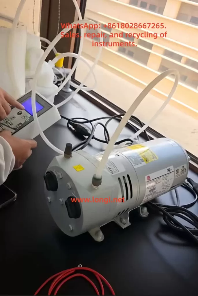
WS-650 Spin Coaters Control Pump Start

1. Why “Hearing the Pump Make a Sound” Does Not Equate to a Normal Vacuum System

In industrial equipment maintenance, a common misconception is to equate “having an action” with “normal functionality.” For example, just because a contactor closes does not mean the main circuit is necessarily conducting; just because a fan is running does not mean the air pressure is sufficient; similarly, just because the vacuum pump makes a sound does not mean that the substrate clamping vacuum in the spin coater has been truly established.

The vacuum retention in a Laurell WS-650 does not simply involve the pump starting up and immediately adhering the substrate. Several conditions must be met simultaneously: First, the external vacuum source must provide sufficient negative pressure; second, the controller must allow the pneumatic vacuum valve to open; third, the vacuum channel must be well-sealed with no leaks; fourth, the sample must correctly cover the O-ring to form an effective sealing surface; fifth, the vacuum detection value must meet the interlock requirements. In other words, the vacuum pump is merely one of the “sources” in the entire system and should not be the sole basis for fault judgment.

If the external pump is running but the pneumatic vacuum valve does not open, the negative pressure will not reach the chuck surface. Even if the valve opens, if the sample does not cover the O-ring, the system will continuously leak air. If the O-ring is aged, contaminated with glue, or installed in the wrong position, continuous leakage will also occur. If the vacuum path has been contaminated with chemical liquids, the valve spool may become sticky and jammed, resulting in the pump working at the rear end but no effective adsorption force at the front end. Therefore, when facing such faults, maintenance personnel should not停留在 (remain stuck at) the superficial judgment of “whether the pump is making a sound” but should focus on the core issue of “whether the negative pressure truly reaches the chuck surface and forms stable retention.”

2. Working Principle of the Laurell WS-650 Vacuum System

To truly understand this fault, it is essential to first grasp the vacuum control structure of the Laurell WS-650. The vacuum retention function of this model is not fully electrically driven but incorporates a certain pneumatic control logic. Simply put, the external vacuum source is responsible for providing negative pressure, and the internal vacuum valves of the equipment determine whether this negative pressure is introduced to the chuck. The action of these valves is related to other interlock conditions of the equipment, with the most typical being the sealing purge gas from CDA (Clean Dry Air) or N2.

Many users do not realize the direct causal relationship between the “Need CDA” message on the screen and the “vacuum not adhering” issue. In fact, CDA or N2 is not just an auxiliary gas source; it is also related to the internal sealing purge and some interlock actions of the equipment. As long as there is a lack of this gas source, insufficient pressure, or incorrect connection, the equipment may not allow the vacuum valve to operate normally or may determine in its logic that the system does not meet the operating conditions. At this point, a typical phenomenon occurs: the external vacuum pump makes a sound, but there is no adsorption force on the substrate, and the screen simultaneously displays a CDA-related alarm.

From the perspective of equipment design logic, this approach is reasonable. During high-speed rotation of the spin coater, if the shaft seal protection is insufficient, the cavity interlock is not established, the vacuum retention is unreliable, the risks of sample fly-off, liquid backflow, bearing contamination, and process failure significantly increase. Therefore, manufacturers incorporate multiple conditions, such as vacuum retention, sealing gas, cover status, and exhaust status, into the interlock system rather than allowing the equipment to operate勉强地 (reluctantly or suboptimally) in a “semi-normal” state.
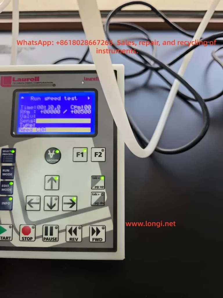
WS-650 Spin Coaters run speed test

3. The Most Common Misjudgment: Treating “Need CDA” as an Irrelevant Prompt

When troubleshooting on-site, a common erroneous approach is to focus solely on “vacuum not working” and ignore other prompt messages at the bottom of the screen. In fact, if the screen displays “Need CDA,” it is no longer a mere附属 (supplementary) prompt but may very well point to the root cause of the fault. In Laurell WS-650 equipment, CDA or N2 compressed gas is not optional. As long as its pressure is insufficient, the valve is not open, the gas pipe is connected incorrectly, or the pressure regulator is set too low, the equipment may determine that the seal purge condition is not met, thereby affecting the opening or maintenance of the vacuum valve.

At this point, if maintenance personnel do not first check the gas source but instead directly disassemble the vacuum pump, replace it, or disassemble the control board, they are likely to go astray. Especially when third-party service personnel take over fault cases at customer sites, customers often describe the problem in very simplified terms, such as “the vacuum not working” or “pump has sound but no hold.” If maintenance personnel only take these descriptions at face value, they may overlook the true clues on the control screen.

Therefore, when dealing with such faults, the first principle is to first look at the complete prompts on the screen and not just rely on the customer’s verbal description. Just because the customer says “the vacuum is not working” does not mean the fault is solely related to the vacuum; if the screen already tells you “Need CDA,” it indicates that the controller has detected that the gas source conditions are not met, rather than a simple pump failure.

4. Why CDA or N2 Gas Source Anomalies Can Cause Vacuum Malfunctions

Many people wonder why insufficient compressed air can affect the vacuum. This actually involves the internal pneumatic valve structure and sealing logic of Laurell equipment. For such spin coaters, some valves rely on pneumatic control for switching, and the equipment also uses dry gas to protect motor seals and specific cavity areas. If the gas source pressure is insufficient, on the one hand, the internal valves may not switch correctly; on the other hand, the controller will prevent the system from entering normal operating status.

More critically, in addition to participating in the interlock, the sealing purge gas also serves a protective function. During the spin coating process, media such as photoresist, solvents, and cleaning liquids are often used. Without sufficient positive gas pressure protection, these liquids may infiltrate the vacuum channel or mechanical seal areas along unwanted paths. Over time, not only will the vacuum retention deteriorate, but the vacuum valve itself may also become contaminated, resulting in stickiness, adhesion, or even jamming. In other words, an initial lack of CDA may be just a gas source problem, but if the equipment continues to operate with the fault, it may gradually evolve into a mechanical fault of the vacuum valve.

The most typical on-site situations include: the gas source valve is not open; the pressure regulator output is lower than required; the dry air shares a gas source with other equipment, causing pressure fluctuations; the white gas pipe is plugged into the wrong interface; the quick-connect fitting is not fully inserted; the filter is clogged, resulting in low downstream pressure; or a temporary gas source is used for testing on-site, and although there is airflow, the pressure does not meet the equipment requirements. For third-party engineering personnel, these problems are often more common and worth prioritizing for inspection than damage to the electronic control board.

5. Incorrect Sample Coverage of the O-ring: The Most Common “Non-equipment Fault”

In addition to gas source problems, another high-frequency cause is that the sample does not correctly cover the O-ring. Many users assume that as long as they place the substrate on the chuck and press the vacuum button, it should adhere. However, the vacuum retention of a spin coater relies on the formation of a sealing surface between the sample and the O-ring. If the sample size is too small, the position is off-center, the wrong fixture is used, or a fragmented substrate is placed on an inappropriate adapter, even if the vacuum pump and vacuum valve are functioning perfectly, the system will leak air and fail to establish sufficient negative pressure due to the lack of a proper seal.

This problem is most likely to occur when working with small samples, glass sheets, or fragmented substrates. Many laboratory users, for the sake of convenience, directly place a small glass sheet on a large chuck and then complain about “vacuum problems.” In fact, this is not an equipment fault but rather a mismatch between the tooling and the sample. For small-sized samples, a corresponding fragment adapter must be used, and only an O-ring of the matching size should be installed. If the wrong O-ring is selected, two O-rings are installed simultaneously, or the sample does not press against the sealing ring, the system will inevitably leak air.

Therefore, when judging vacuum faults, it is essential to distinguish between “equipment abnormalities” and “unsatisfied usage conditions.” Otherwise, it is common for engineers to disassemble the equipment for a long time only to find that the customer simply placed a sample that was too small and did not cover the O-ring. Such low-level misjudgments not only waste time but also undermine the professionalism of the maintenance judgment.

6. O-ring Contamination, Aging, or Incorrect Installation: Important Causes of Unstable Vacuum

Although an O-ring may seem like just a small rubber ring, it plays a crucial role in the vacuum system of a spin coater. It serves as both the sealing interface between the sample and the chuck and the first barrier to prevent liquids from entering the vacuum channel. As long as the O-ring is deformed, cracked, gapped, chemically swollen, has adhesive residue on its surface, or is not installed properly, the system will continuously leak air during the vacuum establishment process, resulting in weak adsorption force, an inability to reach the required vacuum value, or even a complete failure to start the program.

Many on-site faults are related to the condition of the O-ring. For example, after long-term use of certain solvents, the material of the O-ring may swell, changing its cross-sectional dimensions and leading to poor sealing; if the user does not clean it properly, photoresist residue may remain near the O-ring, causing an uneven contact surface; or the customer may install the O-ring backward, askew, or twisted when replacing the adapter. In laboratory environments, these problems are almost more common than hardware damage.

When third-party maintenance personnel receive such repair requests, they should develop a basic habit: first visually inspect the O-ring and the chuck surface and not rush to suspect the control board. As long as there is an abnormality in the sealing surface of the O-ring, the vacuum value will inevitably be unstable, and this instability is often misdescribed by customers as a “pump problem” or “vacuum valve issue.” If on-site conditions permit, a comparison test can also be conducted using a flat, appropriately sized dummy wafer. If the vacuum returns to normal after replacing it with a standard substrate, hardware faults in the pump and valve can be largely ruled out.

7. Vacuum Valve Contamination by Chemical Liquids: A Typical and Stubborn Fault in Spin Coaters

In the repair cases of Laurell WS-650 spin coaters, vacuum valve contamination is a very typical and often overlooked underlying fault. During the operation of a spin coater, the工艺 (process) liquids are usually located on the upper surface of the sample. However, if the vacuum retention is insufficient, the O-ring fails, or the user operates improperly during cleaning, liquids may seep into the vacuum channel along the gaps. Once photoresist, polyimide, or other viscous liquids enter the vacuum path, they may adhere to the internal piston or sealing surface of the vacuum valve, causing the valve spool to move sluggishly, jam, or seal poorly.

The most troublesome aspect of this fault is that its manifestations are very similar to those of insufficient external gas source pressure. On-site, it may also appear as a lack of stable adsorption after pressing the vacuum button, with the pump seemingly making a sound but poor front-end performance. The difference is that if the CDA is normal, the sample coverage is correct, the O-ring condition is good, but the vacuum still cannot be established, then there is a high suspicion of internal contamination of the vacuum valve.

Many users, when cleaning the spin coating cavity, spray a large amount of acetone or other solvents for the sake of convenience and sometimes even directly flush the chuck or sealing area. This approach may seem clean in the short term but can easily introduce dissolved photoresist and impurities into the vacuum path over the long term. Some people also use compressed air to directly blow into the vacuum hole to speed up drying, which can同样 (likewise) press liquids or particles into the interior. For small pneumatic components like vacuum valves, once the interior is contaminated, the valve may move sluggishly at best and become completely jammed at worst, ultimately resulting in what customers describe as a “broken vacuum.”

Therefore, in fault analysis, if the customer’s equipment has a history of long-term use of photoresist, thick coatings, polyimide, viscous coatings, or frequent solvent cleaning, the probability of vacuum valve contamination increases significantly. In terms of maintenance strategy, this type of fault usually cannot be determined solely through external observation but requires a comprehensive analysis based on the front-end vacuum performance, gas source status, piping status, and historical usage habits.

8. The External Vacuum Source Itself May Indeed Have Problems, but It Is Usually Not the First Priority

Of course, the vacuum pump itself or the external vacuum piping is not entirely immune to faults. For example, pump blade wear, pump cavity blockage, filter clogging, air intake leaks, piping aging and cracking, hose kinking and collapse, fitting loosening, and abnormal exhaust can all lead to insufficient vacuum. However, in Laurell WS-650 cases, if the screen clearly displays a CDA prompt, the external pump itself should not be the first suspect.

The scenarios where it is truly necessary to prioritize checking the pump itself are as follows: the CDA is normal, and the screen no longer displays gas source-related prompts; the sample and O-ring are fully matched; the O-ring is clean and intact; the vacuum valve action can be confirmed; but the system still cannot reach the required vacuum value. Only then is it logical to suspect insufficient pump performance. Otherwise, immediately replacing the pump upon seeing a lack of adhesion is often a typical error in maintenance sequence.

From engineering experience, external pump faults usually exhibit more explicit characteristics, such as a long-term inability to reach the required vacuum value, abnormal pump noise, abnormal temperature rise, abnormal exhaust at the pump outlet, and an inability to reach basic negative pressure even when disconnected from the equipment for separate testing. If the customer only says “the pump can be heard making a sound,” it actually only indicates that the pump motor may be running and does not prove that the pump efficiency is normal, let alone that the internal interlock of the equipment has been released.

9. How to Quickly Establish a Correct Fault Judgment Logic Based on On-site Phenomena

For third-party readers, the most valuable aspect is not memorizing the name of a specific part but establishing a replicable judgment path. When facing the problem of “the vacuum pump makes a sound, but the spin coater does not adhere,” the best approach is not to immediately disassemble the machine but to first narrow down the scope in a logical order.

Step 1: Look at the screen prompts. If there are messages like “Need CDA,” prioritize addressing the gas source problem; if there are only vacuum-related prompts, then proceed to check the sample, O-ring, and vacuum path. Step 2: Examine the sample status. Check whether the sample is large enough, whether it fully covers the O-ring, whether the correct adapter is used, and whether the position is centered. Step 3: Inspect the O-ring status. Check for aging, deformation, adhesive contamination, or incorrect installation. Step 4: Check the external connections. Verify whether the vacuum and gas pipes are connected correctly, whether the quick-connect fittings are loose, and whether the hoses are kinked. Step 5: Only then consider vacuum valve contamination or insufficient external pump performance.

The advantage of this troubleshooting path is that it prioritizes the exclusion of the most common, least expensive, and easiest-to-verify problems, minimizing the risk of disassembly. Because many on-site faults ultimately turn out not to be caused by a damaged main board or pump but rather by issues such as an unopened gas source, an incorrectly placed sample, a dirty O-ring, or a loose fitting. True professionalism lies not in immediately replacing parts but in using the fewest actions to eliminate the most uncertainties.

10. A Typical On-site Misconception: Interpreting Program Run Failures as Electronic Control Faults

In the program running logic of the Laurell WS-650, vacuum retention is just one of the startup conditions. If the equipment’s vacuum retention is not satisfied, the program may not enter the normal running state at all or may stop running immediately after starting. Some operators, upon seeing that the program cannot run, immediately suspect problems with the controller, keypad, or program parameters and even believe that there are issues with interface elements such as F1, F2, and Run Mode. In fact, in many cases, the controller itself is completely normal; it is simply faithfully executing the interlock logic.

This is also why third-party maintenance personnel should not focus solely on the表象 (superficial phenomenon) of “the program not running” during troubleshooting. A spin coater is essentially a process equipment, not an ordinary household appliance. Its controller integrates many mechanical and pneumatic conditions for comprehensive judgment. As long as the vacuum retention is insufficient, the cover is not closed, the sealing gas pressure is insufficient, or the exhaust status is incorrect, the controller will prohibit running or interrupt the running process. Therefore, program failures are not necessarily program problems, and interface error codes do not necessarily indicate board card problems; often, they are simply reminding the operator that the peripheral conditions are not met.

11. Why Third-party Maintenance Personnel Must Pay Attention to Customers’ Usage Habits and Cleaning Methods

Industrial equipment faults are never just about “parts being broken”; in many cases, they are the cumulative result of usage methods. This is especially true for spin coaters. Many vacuum problems do not occur suddenly on a particular day but are the result of long-term non-standard usage. For example, regularly placing small samples directly on a large chuck; frequently using O-rings of inappropriate materials; extensively flushing the sealing area during cleaning; allowing sample coating leakage without timely treatment; not cleaning the adapter after use and directly reinstalling it; mixing different chemical systems, causing seal expansion; and failing to restore the standard O-ring configuration in a timely manner after shutdown, etc.

These behaviors may not immediately cause faults in the short term but can gradually damage the vacuum path and valves. By the time the customer realizes that “the vacuum cannot be established no matter what,” it is often no longer a single minor issue but a combination of usage, maintenance, and interlock condition problems. If third-party maintenance personnel ignore this aspect and simply replace parts mechanically, they are likely to only provide a temporary
Posted on

Mechanism Analysis and Maintenance-Level Troubleshooting Guide for A.410 Undervoltage Fault in Yaskawa Σ-5 (SGDV) Servo Drives

I. Fault Definition and Engineering Background

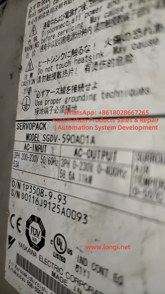
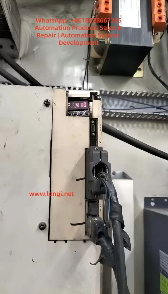
In the Yaskawa Σ-5 series servo system (SERVOPACK, with a typical model like SGDV-590A01A), the alarm code A.410 indicates:

The DC bus voltage in the main circuit is below the allowable threshold (Undervoltage Fault).

This alarm does not simply imply a low input voltage. Instead, the drive detects internally that:

  • The DC bus voltage after rectification is insufficient.
  • Or the bus voltage drops abnormally during operation.

According to the definition in the Σ-5 series manual, this alarm is usually triggered under the following conditions:

  • For an AC200V system: The bus voltage is below approximately DC170V.
  • For an AC400V system: The bus voltage is below approximately DC340V.

This means:

The essence of A.410 is an “energy chain break” problem, not a single-point voltage issue.

SGDV-590A01A

II. Main Circuit Structure and Fault Logic of SGDV

To fully understand A.410, it is essential to first understand the main circuit topology of SGDV:

Three-phase AC input

Diode bridge (rectifier)

Pre-charge resistor

Pre-charge relay (bypass relay)

DC bus capacitor (bulk capacitor)

IGBT inverter module

Core detection points:
The drive continuously monitors the voltage of the DC BUS (P+ / N-).

III. Three Major Root Causes of A.410 Triggering

1️⃣ External Power Supply Anomalies (System-Level Issues)

Typical causes:

  • Three-phase phase loss
  • Low input voltage (< 180V)
  • Excessive impedance in the power supply line
  • Poor contact of contactors

Characteristics:

  • The alarm occurs immediately upon power-up.
  • All drives may be abnormal simultaneously.

2️⃣ Instantaneous Voltage Drops (Dynamic Issues)

Typical causes:

  • Simultaneous startup of large-load equipment
  • Grid fluctuations
  • Abnormal braking energy feedback

Characteristics:

  • Occurs occasionally during operation.
  • Recovers after resetting.

3️⃣ Internal Faults in the Drive (Focus of Maintenance)

This is the part that maintenance personnel must focus on:

Key fault points:

PartFailure Mode
Diode bridgeOpen-circuit/short-circuit of diodes
Pre-charge resistorOpen-circuit
Pre-charge relayFailure to engage
DC bus capacitorReduced capacitance/increased ESR
Voltage detection circuitAbnormal voltage division
A410 FAULT

IV. Engineering-Level Diagnostic Process (Standard Steps)

Step 1: Input Power Confirmation

Measure:

  • L1-L2
  • L2-L3
  • L1-L3

Standard:

  • For a 200V system: 200 – 230V
  • Phase-to-phase deviation < 5%

Judgment logic:

  • ❌ If any phase is missing → External problem.
  • ❌ If the voltage is low → Power supply problem.

Step 2: DC Bus Voltage Measurement (Core Step)

Measurement point:

  • P+ and N-

Normal values:

Input VoltageDC Bus Voltage
200V AC280 – 320V DC

Result judgment:

Measured ValueConclusion
NormalRule out main circuit issues.
Significantly lowInternal fault.
No voltageRectifier/pre-charge problem.

Step 3: Pre-charge Process Analysis

Normal process:
Power-up → Current-limited charging through resistor → Bus voltage rises → Relay engages (bypass resistor).

Abnormal manifestations:

  • No “relay engagement sound”.
  • Bus voltage does not rise.

Direct conclusion:
Pre-charge circuit fault.

Step 4: Dynamic Operation Detection

Observe:

  • Whether there is a power drop during startup.
  • Whether the alarm occurs during acceleration.

If the alarm only occurs during operation:
Focus on checking the bus capacitor and grid stability.

V. In-Depth Maintenance-Level Analysis

1️⃣ Diode Bridge Fault

Manifestations:

  • Low DC bus voltage.
  • Large voltage fluctuations.

Detection method:
Use a multimeter in diode mode to test in six directions.
Check for single-phase rectification.

2️⃣ Pre-charge Circuit Fault (Most Common)

Components:

  • Pre-charge resistor
  • Relay
  • Control drive circuit

Fault manifestations:

  • Bus voltage stalls at a low value (e.g., 100 – 200V).
  • No relay engagement sound.

Judgment technique:
Observe the voltage change curve during power-up.

3️⃣ DC Bus Capacitor Degradation

Manifestations:

  • Normal startup.
  • Voltage drop during operation.

Causes:

  • Increased ESR.
  • Reduced capacitance.

Detection method:
Test with an ESR meter.
Observe the ripple voltage.

4️⃣ Voltage Detection Circuit Anomaly

Components:

  • Voltage-dividing resistors
  • Operational amplifier
  • ADC input

Manifestations:

  • The actual voltage is normal, but the alarm is triggered.

Action required:
Compare the actual measured value with the drive’s displayed value.

VI. Typical Case Studies (Practical Examples)

Case 1: A.410 Alarm Immediately upon Power-up

  • Normal input.
  • DC bus voltage is only 120V.

Conclusion:
The pre-charge relay did not engage.

Case 2: Occasional A.410 Alarm during Operation

  • Normal startup.
  • Alarm during acceleration.

Conclusion:
High ESR of the capacitor.

Case 3: Alarm after Replacing the Power Supply

Conclusion:
Input phase sequence or voltage mismatch.

VII. Quick Location Techniques (On-Site Practical)

Technique 1: Listen to the Relay

  • “Click” sound → Normal.
  • No sound → Pre-charge problem.

Technique 2: Observe the Bus Voltage Curve

  • Smooth rise → Normal.
  • Stagnation → Pre-charge resistor problem.
  • Sudden drop → Capacitor problem.

Technique 3: Compare Multiple Devices

  • Alarms occur simultaneously → Power supply problem.
  • Alarm on a single device → Internal problem.

VIII. Maintenance Recommendations and Replacement Strategies

Priority of must-replace components:

  1. Pre-charge relay
  2. Electrolytic capacitor
  3. Diode bridge

Do not blindly replace:

  • Control board
  • CPU module

Unless it is confirmed that there is an anomaly in the detection circuit.

IX. Preventive Measures (Engineering Level)

Power Supply Side:

  • Use a voltage stabilizer.
  • Avoid long-distance power supply.

Equipment Side:

  • Regularly replace capacitors (every 5 – 7 years).
  • Check contactors.

System Design:

  • Add bus monitoring.
  • Reasonably configure braking units.

X. Summary

A.410 is not simply a “low voltage” alarm but a comprehensive manifestation of anomalies in the servo system’s energy supply chain.

From a maintenance perspective, the core of diagnosis lies in:

  • Determining whether it is an external or internal problem.
  • Focusing on the DC bus voltage as the key variable.
  • Prioritizing the troubleshooting of the pre-charge circuit.

In actual maintenance:

  • Over 80% of A.410 faults are caused by pre-charge or bus issues.
  • Mastering the system structure and voltage change patterns is more crucial than simply checking the alarm code.
Posted on

Siemens SINAMICS S120 Fault F07453: Meaning, Root Cause Analysis, and Practical Troubleshooting Guide

1. Fault Overview

In Siemens SINAMICS S120 drive systems, F07453 is a position feedback-related fault. Its typical meaning is:

LR: Position actual value preprocessing error

In practical terms, this means the drive cannot correctly process the actual position feedback required by the position control loop.

This fault is not normally related to a DC bus power failure, rectifier fault, motor overload, or main power module short circuit. It is mainly associated with the encoder feedback chain, position actual value processing, and position loop encoder assignment.

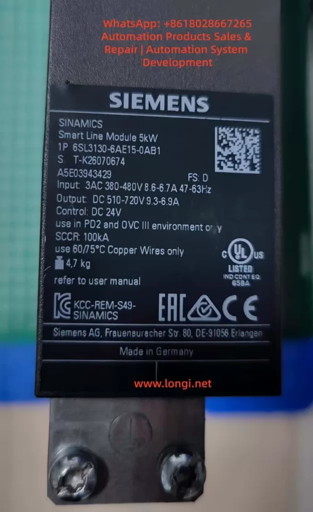
SINAMICS S120 is a modular high-performance multi-axis drive system. A typical system may include a Smart Line Module, Active Line Module, Motor Module, Control Unit, Sensor Module, DRIVE-CLiQ communication network, motor encoder, external measuring system, and BOP20 operator panel. Because of this modular architecture, fault F07453 must be analyzed systematically instead of simply judging the drive as defective.

The key point of F07453 is:

The drive cannot obtain or process a valid actual position value for the position control loop.


F.07453 fault

2. Technical Meaning of F07453

In a servo drive system, the position loop normally depends on three basic values:

  1. Position setpoint
    This is the target position from the PLC, CNC, motion controller, or internal positioning function.
  2. Position actual value
    This is the real mechanical position feedback from the motor encoder, external encoder, linear scale, rotary encoder, or other measuring system.
  3. Position deviation
    This is the difference between the position setpoint and the position actual value.

For SINAMICS S120, the encoder signal cannot always be used directly. The drive must first process the feedback signal. This preprocessing may include:

  • Detecting whether the encoder exists;
  • Identifying the encoder type;
  • Checking encoder communication;
  • Checking encoder supply voltage and signal validity;
  • Reading encoder resolution;
  • Processing incremental or absolute position data;
  • Checking the zero pulse or reference mark;
  • Checking encoder direction;
  • Converting encoder data into mechanical position;
  • Calculating electrical angle when required;
  • Processing multiturn absolute encoder data;
  • Checking the encoder data set;
  • Confirming which encoder is assigned to the position loop;
  • Converting the feedback into an internal actual position value.

This process is called position actual value preprocessing.

Therefore, F07453 does not simply mean “the encoder is bad”. Its more accurate meaning is:

The drive failed while converting the encoder or measuring system feedback into a valid actual position value for the position control loop.

This failure may be caused by hardware, wiring, parameter configuration, DRIVE-CLiQ topology, encoder assignment, data set mismatch, or mechanical feedback problems.


3. Why F07453 Should Not Be First Treated as a Power Module Fault

A SINAMICS S120 booksize system is usually composed of several modules:

ModuleMain Function
Smart Line Module / Active Line ModuleConverts three-phase AC input into DC link voltage
Motor ModuleConverts DC link voltage into three-phase motor output
Control UnitHandles axis control, communication, parameters, and system logic
Sensor ModuleProcesses external encoder or measuring system signals
DRIVE-CLiQInternal high-speed communication link
BOP20Local operation and fault display panel

If the Smart Line Module or Active Line Module is faulty, the fault usually relates to input power, rectification, pre-charging, DC bus voltage, regenerative operation, temperature, or input phase loss.

If the Motor Module power section is faulty, the fault usually relates to overcurrent, ground fault, short circuit, IGBT failure, output phase loss, or motor insulation failure.

However, F07453 belongs to the position feedback and position actual value processing category. The main focus is not the power circuit, but whether the drive can receive and process valid feedback for the position loop.

Therefore, when troubleshooting F07453, the first priority should be:

  1. Encoder;
  2. Encoder cable;
  3. Encoder connector;
  4. Sensor Module;
  5. DRIVE-CLiQ communication;
  6. Encoder parameters;
  7. Position loop encoder assignment;
  8. Motor and encoder data sets;
  9. Drive Object configuration;
  10. Mechanical feedback system.

The Smart Line Module or main power section should only be considered after the feedback chain and parameter configuration have been checked.


6SL3130-6AE15-0AB1

4. Common Causes of F07453

4.1 Encoder Failure

The encoder is the source of the actual position value. If the encoder fails, the drive may not receive valid position feedback and may trigger F07453.

Common encoder-related problems include:

  • Internal encoder circuit failure;
  • Encoder power supply short circuit;
  • Contaminated optical encoder disc;
  • Damaged magnetic encoder ring;
  • Abnormal multiturn absolute encoder data;
  • EnDat, SSI, or DRIVE-CLiQ encoder communication failure;
  • Weak A/B/Z incremental signals;
  • Distorted Sin/Cos signals;
  • Damaged encoder memory data;
  • Moisture, oil, or dust inside the encoder;
  • Poor contact inside the encoder connector.

If the drive reports F07453 immediately after power-on or immediately after enable, the encoder should be checked first. When the motor shaft is turned manually, the actual position value should change continuously in the engineering software. If the value does not change, jumps randomly, changes in the wrong direction, or becomes invalid, the encoder or feedback chain is highly suspicious.


4.2 Encoder Cable, Connector, or Shielding Problem

The encoder cable is one of the most common causes of F07453. Encoder signals are weak signals, especially Sin/Cos, TTL, HTL, SSI, and EnDat signals. They are sensitive to cable quality, shielding, grounding, and connector reliability.

Typical cable and connector problems include:

  • Loose encoder connector;
  • Bent, oxidized, or retracted connector pins;
  • Oil or moisture inside the connector;
  • Broken wire inside a drag chain cable;
  • Damaged shield layer;
  • Poor shield grounding;
  • Encoder cable bundled together with motor power cable;
  • Encoder cable routed near contactors, braking resistors, or other high-interference sources;
  • Incorrect wiring in a custom-made encoder cable;
  • Cable length exceeding the recommended limit;
  • Cable mechanically crushed or stretched.

If F07453 occurs only at a certain machine position or randomly during movement, a broken wire inside the drag chain should be suspected. Static continuity measurement with a multimeter may not reveal the problem. The cable may appear normal when stationary but fail during movement.

In this case, replacing the encoder cable with a known good cable is often more effective than simple continuity testing.


4.3 Encoder Power Supply Problem

Different encoders require different supply voltages, such as 5 V, 10 V, 24 V, or 10–30 V. If the encoder supply is unstable or incorrect, the encoder cannot output valid feedback signals.

Typical problems include:

  • No encoder supply voltage;
  • Low encoder supply voltage;
  • Excessive ripple on the encoder supply;
  • Insufficient current capacity;
  • Poor contact in the supply wires;
  • Internal encoder short circuit pulling down the supply;
  • Abnormal 0 V reference;
  • Incorrect shorting between shield and signal ground;
  • Damaged encoder supply output from the Sensor Module.

The encoder supply should be measured with the encoder connected, not only under no-load conditions. A no-load voltage may appear normal, but the voltage may drop significantly when the encoder is connected and operating.


4.4 Sensor Module Failure or Incorrect Configuration

In many S120 systems, encoder feedback is connected through SMC or SME Sensor Modules rather than directly through the motor. If the Sensor Module fails or is incorrectly configured, F07453 may occur.

Possible Sensor Module-related causes include:

  • Faulty SMC20, SMC30, or other Sensor Module;
  • Abnormal module power supply;
  • Communication problem between Sensor Module and Control Unit;
  • Poor connector contact;
  • Encoder type incompatible with the Sensor Module;
  • Changed DRIVE-CLiQ topology;
  • Module replaced but not re-identified;
  • Actual module type different from the configured module type;
  • Wrong encoder data set assignment.

If several identical Sensor Modules are available on the machine, cross-swapping can be used to determine whether the fault follows the module.


4.5 DRIVE-CLiQ Communication or Topology Problem

DRIVE-CLiQ is the internal communication system used by SINAMICS S120 to connect the Control Unit, Motor Modules, Sensor Modules, and DRIVE-CLiQ motors. Although F07453 is not purely a communication fault, DRIVE-CLiQ problems can prevent encoder data from being correctly identified or used.

Typical DRIVE-CLiQ-related causes include:

  • Loose DRIVE-CLiQ cable;
  • Damaged DRIVE-CLiQ cable;
  • Changed topology sequence;
  • Topology mismatch after module replacement;
  • Dirty or oxidized DRIVE-CLiQ connector;
  • Incorrect cable used instead of a suitable DRIVE-CLiQ cable;
  • Actual wiring different from the project topology;
  • Control Unit unable to identify a node correctly.

The S120 system is sensitive to topology. After replacing modules or reconnecting cables, the actual DRIVE-CLiQ topology must match the project configuration.


4.6 Incorrect Position Loop Encoder Assignment

F07453 is closely related to encoder assignment in the position loop. In a S120 axis, the position feedback source may be:

  • Motor encoder;
  • Second encoder;
  • Load-side encoder;
  • Linear scale;
  • Rotary encoder;
  • Direct measuring system;
  • Virtual encoder;
  • Actual position value from a higher-level controller.

The position loop must know exactly which feedback source to use. If the position loop is assigned to a non-existing, inactive, invalid, or incorrectly configured encoder, F07453 may occur.

Typical examples include:

  • The machine only has a motor encoder, but the position loop is assigned to encoder 2;
  • The system uses a load-side scale, but the project still points to the motor encoder;
  • The encoder data set was not created after motor replacement;
  • A Drive Data Set refers to the wrong Encoder Data Set;
  • Parameters copied from another axis created encoder assignment mismatch;
  • Project download cleared or changed the position feedback source.

In this situation, the hardware may be completely normal, but the drive still cannot use the actual position value because the assignment is wrong.


4.7 Motor, Encoder, and Drive Parameter Mismatch

SINAMICS S120 is a highly parameterized servo system. Motor data, encoder data, power module data, mechanical transmission ratio, control mode, and topology must match each other.

Common mismatch cases include:

  • Motor replaced with a different model;
  • Encoder replaced with a different type;
  • Substitute motor used without parameter update;
  • Motor nameplate data not matching the project;
  • Encoder pulse number set incorrectly;
  • Absolute encoder bit number set incorrectly;
  • Sin/Cos interpolation setting incorrect;
  • Motor pole pair number incorrect;
  • Mechanical transmission ratio incorrect;
  • Encoder direction incorrect;
  • Motor Data Set and Encoder Data Set not matching;
  • Drive Object parameters copied from another machine.

This type of problem is common after maintenance, especially when used spare parts, repaired modules, replacement motors, or copied CF card data are involved. Two motors may look physically similar but have completely different encoder systems.


4.8 Mechanical Feedback System Problem

Although F07453 mainly points to feedback signal processing or parameter assignment, mechanical problems can also cause abnormal actual position feedback, especially when a load-side encoder or linear scale is used.

Possible mechanical causes include:

  • Loose encoder coupling;
  • Broken encoder shaft;
  • Slipping belt;
  • Excessive gearbox backlash;
  • Contaminated linear scale head;
  • Loose scale installation;
  • Load encoder direction opposite to motor encoder direction;
  • Mechanical axis jammed;
  • Reference switch problem;
  • Lost machine zero point;
  • External measuring system shifted from its original position.

If the system uses dual encoders, such as a motor encoder for the speed loop and a load-side encoder for the position loop, checking only the motor encoder is not enough. The actual feedback source used by the position loop must be confirmed.


5. Systematic Troubleshooting Procedure

5.1 Identify the Faulty Drive Object

S120 is a multi-axis system. One Control Unit may manage several Drive Objects. When BOP20 displays F07453, the first step is to identify which Drive Object is reporting the fault.

The following information should be confirmed:

  • Drive No.;
  • Drive Object name;
  • Related Motor Module channel;
  • Related motor;
  • Related encoder;
  • Related Sensor Module;
  • Whether the axis uses position control;
  • Whether EPOS is used;
  • Whether a second encoder or external measuring system is used.

Without identifying the correct axis, troubleshooting may focus on the wrong motor or module.


5.2 Read Fault Records and Fault Values

Fault records should be read through BOP20, STARTER, or Startdrive.

Important information includes:

  • Current fault code;
  • Fault value;
  • Fault time;
  • Faulty Drive Object;
  • Associated alarms or faults;
  • Whether the fault occurs at power-on, enable, running, homing, or positioning;
  • Whether the fault can be reset;
  • Whether it returns immediately after reset.

If F07453 appears together with encoder, DRIVE-CLiQ, encoder supply, or encoder data set alarms, those associated messages should guide the next step.


5.3 Check Encoder Connector and Cable

This is the most practical field inspection step.

Recommended checks:

  1. Power off and reconnect the encoder connector;
  2. Check the connector locking mechanism;
  3. Inspect pins for bending, oxidation, or retraction;
  4. Check the cable jacket for damage;
  5. Inspect drag chain sections;
  6. Check whether the cable is crushed or stretched;
  7. Confirm proper shield connection;
  8. Separate encoder cable from motor power cable;
  9. Check cabinet grounding;
  10. Replace with a known good encoder cable for testing.

Encoder cable problems should not be judged only by static continuity measurement. Signal quality, shielding, dynamic bending, and high-frequency integrity are equally important.


5.4 Check Encoder Supply and Signal

For traditional encoders such as incremental, Sin/Cos, SSI, or EnDat, encoder supply and signal quality should be checked.

Supply checks:

  • Correct supply voltage;
  • No voltage drop under load;
  • Low ripple;
  • Reliable 0 V reference;
  • No short to ground;
  • Sensor Module encoder supply output normal.

Signal checks:

  • A/B signals present;
  • Z pulse or reference mark present if required;
  • Sin/Cos amplitude normal;
  • SSI / EnDat communication stable;
  • Signal changes continuously when shaft rotates;
  • No spikes, missing pulses, or amplitude collapse;
  • Shielding effective.

If an oscilloscope is used, grounding must be handled carefully to avoid creating a short circuit or introducing interference.


5.5 Monitor the Actual Position Value Online

Using STARTER or Startdrive to monitor the actual position value is one of the most important diagnostic methods.

When the motor shaft is manually turned under safe conditions, the actual position value should:

  • Change continuously;
  • Change in the correct direction;
  • Not jump randomly;
  • Not become invalid;
  • Not disappear intermittently;
  • Show normal encoder status;
  • Show normal topology status.

Abnormal symptoms include:

  • Position value does not change;
  • Position value jumps randomly;
  • Direction is reversed;
  • Value suddenly resets;
  • Value becomes invalid;
  • Encoder cannot be detected;
  • Encoder status appears and disappears;
  • Fault occurs immediately when the shaft is turned.

These observations can help distinguish between encoder, cable, Sensor Module, and parameter problems.


5.6 Check Position Loop Encoder Assignment

If the encoder appears online but F07453 remains, the position loop encoder assignment must be checked.

Key points:

  • Whether position control is enabled;
  • Which feedback source is assigned to the position loop;
  • Whether the assigned encoder actually exists;
  • Whether a second encoder is configured;
  • Whether an external measuring system is used;
  • Whether the Encoder Data Set is valid;
  • Whether Drive Data Set switching changes encoder reference;
  • Whether copied parameters created encoder number mismatch;
  • Whether topology changes were updated in the project.

If the position loop is assigned to the wrong encoder, the encoder may appear healthy, but the position control loop still cannot use the actual value.


5.7 Check Motor and Encoder Data Sets

If the motor, encoder, Motor Module, Control Unit, CF card, or project has been replaced or modified, the data sets must be verified carefully.

Important checks include:

ItemPossible Problem
Motor modelControl model does not match actual motor
Encoder typeFeedback cannot be processed correctly
Encoder resolutionPosition value conversion error
Encoder directionPosition loop instability or error
Mechanical ratioIncorrect actual position scaling
Motor pole pair numberIncorrect electrical angle calculation
Encoder Data SetInvalid or wrong data set
Drive Data SetWrong feedback source after switching
TopologyActual hardware does not match project

A module that powers up normally is not necessarily correctly configured. In S120 systems, hardware and parameters must match exactly.


5.8 Perform Cross-Swapping Tests

If identical axes or spare modules are available, cross-swapping is an efficient way to identify the fault source.

Recommended sequence:

  1. Swap encoder cables;
  2. Swap DRIVE-CLiQ cables;
  3. Swap Sensor Modules;
  4. Swap motor encoder or complete motor;
  5. Swap Motor Module channel;
  6. Consider Control Unit or CF card only at the final stage.

Judgment table:

Swapped PartIf the Fault FollowsLikely Cause
Encoder cableYesCable problem
Motor / encoderYesEncoder or motor feedback problem
Sensor ModuleYesSensor Module problem
Motor Module channelYesMotor Module interface or channel problem
Parameter / CF cardYesParameter or project problem
Same mechanical axisYesMechanical side or field wiring problem

Parameters must be backed up before cross-swapping. Randomly exchanging Control Units, CF cards, or project files may create new topology or safety configuration problems.


6. Troubleshooting by Fault Scenario

6.1 Machine Was Working Normally, Then Suddenly Reports F07453

In this case, hardware and connection issues are more likely.

Priority checks:

  • Encoder cable damage;
  • Loose encoder connector;
  • Encoder failure;
  • Sensor Module failure;
  • DRIVE-CLiQ cable problem;
  • Shielding or grounding issue;
  • Increased field interference.

Recommended actions:

  1. Check encoder connector and cable;
  2. Check encoder supply voltage;
  3. Replace encoder cable;
  4. Check Sensor Module;
  5. Monitor actual position value;
  6. Replace encoder or motor if necessary.

If no parameter changes were made, the probability of sudden parameter mismatch is lower.


6.2 F07453 Appears After Module Replacement

In this case, topology and parameter mismatch are more likely.

Possible causes:

  • DRIVE-CLiQ topology changed;
  • Replacement module is not exactly the same;
  • Motor Module channel assignment changed;
  • Sensor Module address or connection order changed;
  • Topology was not re-identified;
  • Wrong encoder data set reference;
  • Wrong position loop encoder assignment.

Recommended actions:

  1. Check the actual module type;
  2. Check DRIVE-CLiQ connection sequence;
  3. Re-identify topology online;
  4. Verify Drive Object mapping;
  5. Check position loop encoder assignment;
  6. Download the correct project;
  7. Check encoder status for all axes.

6.3 F07453 Appears After Motor Replacement

This is often caused by encoder type mismatch or unchanged parameters.

Recommended actions:

  1. Compare the complete old and new motor model numbers;
  2. Compare encoder types;
  3. Compare encoder resolution;
  4. Check encoder connector pin assignment;
  5. Reconfigure motor data;
  6. Re-identify the DRIVE-CLiQ motor if applicable;
  7. Check actual position value;
  8. Perform encoder calibration or reference point setup if required.

Servo motors cannot be replaced only by comparing power, speed, and frame size. Encoder type and data are critical.


6.4 F07453 Appears at Power-On but Can Be Reset Later

This usually suggests temperature-related, contact-related, moisture-related, or aging problems.

Possible causes:

  • Cold-state encoder fault;
  • Sensor Module cold solder joint;
  • Oxidized connector;
  • Aging capacitor in encoder supply circuit;
  • Moisture inside cabinet;
  • Intermittent cable contact;
  • Strong interference during power-up.

Recommended actions:

  1. Read the fault immediately in cold state;
  2. Measure encoder supply in cold state;
  3. Check whether the encoder is online in cold state;
  4. Use heat or freeze spray to locate sensitive components;
  5. Check cabinet moisture and oil contamination;
  6. Replace encoder cable;
  7. Check Sensor Module.

A fault that disappears after warm-up should not be ignored, because it often becomes worse over time.


6.5 F07453 Occurs Randomly During Operation

Random F07453 faults are usually related to signal quality, movement, or interference.

Priority checks:

  • Drag chain encoder cable;
  • Vibration at encoder connector;
  • Shield connection;
  • Motor power cable interference;
  • Cabinet grounding;
  • Sensor Module contact;
  • Encoder signal amplitude;
  • Cable tension at certain axis positions.

Recommended actions:

  1. Move the axis to different positions and gently flex the cable;
  2. Inspect drag chain cable sections;
  3. Replace encoder cable;
  4. Separate encoder cable from motor power cable;
  5. Improve shielding and grounding;
  6. Record the axis position when the fault occurs;
  7. Check whether actual position value jumps.

7. Common Misdiagnoses

7.1 Misdiagnosing the Smart Line Module

F07453 concerns position actual value processing. It is not primarily a DC bus or rectifier fault. Replacing the Smart Line Module first is usually not the correct approach.

7.2 Misdiagnosing the Motor Module Power Stage

Motor Module power stage faults usually produce overcurrent, short circuit, ground fault, or output phase faults. F07453 points more strongly to feedback and position processing.

7.3 Checking Only Motor Power Cables

Servo systems depend heavily on encoder feedback. Encoder cables, connectors, shielding, and signal quality must be checked carefully.

7.4 Checking Encoder Presence but Not Feedback Quality

An encoder may be detected but still provide unstable, incorrect, or mismatched position data. The actual position value must be monitored for continuity, direction, and stability.

7.5 Copying Parameters from a Similar Axis

A similar axis may have different encoder direction, mechanical ratio, zero point, limit direction, or safety settings. Blind parameter copying may create more faults.

7.6 Performing Factory Reset Without Backup

S120 systems contain complex motor, encoder, topology, positioning, and safety parameters. A factory reset without a full backup can make recovery much more difficult.


8. Recommended Repair Logic

A practical troubleshooting sequence for F07453 is:

  1. Confirm the system architecture;
  2. Identify the faulty Drive Object;
  3. Read fault records and fault values;
  4. Check associated encoder or DRIVE-CLiQ alarms;
  5. Inspect encoder connector and cable;
  6. Check encoder supply voltage;
  7. Monitor actual position value online;
  8. Check position loop encoder assignment;
  9. Verify motor and encoder data sets;
  10. Check DRIVE-CLiQ topology;
  11. Check Sensor Module;
  12. Perform cross-swapping tests;
  13. Replace encoder, motor, cable, or Sensor Module if confirmed;
  14. Consider Motor Module, Control Unit, or project data only after previous checks.

The key repair principle is:

Check feedback before power hardware; check cable before module; identify the correct axis before replacing parts; back up parameters before making changes.


9. Practical Diagnostic Logic

When a SINAMICS S120 system reports F07453, the fault should be classified as a position feedback processing problem, not simply as “drive failure”.

The actual position value follows this logical path:

Encoder generates position data → encoder cable transmits the signal → Sensor Module or DRIVE-CLiQ receives the signal → Control Unit identifies the encoder → parameter system assigns the encoder → position loop uses the actual value.

Any failure in this chain may trigger F07453.

If the fault appears after replacing a motor, module, Control Unit, CF card, or project download, parameter and topology mismatch should be the main focus.

If the machine has been running normally for a long time and then suddenly reports the fault, encoder, cable, connector, and Sensor Module should be checked first.

If the fault occurs randomly during movement, shielding, grounding, drag chain cable, connector vibration, and signal quality should be checked first.

If the fault occurs during homing, positioning, or enable, position loop feedback assignment, external measuring system, and mechanical reference system should be checked first.

Correct diagnosis depends on chain-based thinking, not single-part guessing.


10. Conclusion

Siemens SINAMICS S120 fault F07453 means position actual value preprocessing error. It indicates that the drive cannot correctly process the actual position feedback required by the position control loop.

This fault is usually related to:

  • Encoder failure;
  • Encoder cable or connector problem;
  • Encoder power supply issue;
  • Sensor Module fault;
  • DRIVE-CLiQ topology or communication problem;
  • Incorrect position loop encoder assignment;
  • Motor and encoder data mismatch;
  • Invalid Encoder Data Set;
  • External measuring system problem;
  • Mechanical feedback system abnormality.

F07453 should not be diagnosed first as a Smart Line Module failure or main power module failure. The correct troubleshooting direction is the position feedback chain.

The most important questions are:

  • Which Drive Object reports the fault?
  • Which encoder is used by the position loop?
  • Is the encoder online and valid?
  • Is the encoder cable reliable?
  • Is the encoder supply stable?
  • Is the Sensor Module working correctly?
  • Is the DRIVE-CLiQ topology correct?
  • Is the encoder assignment correct?
  • Do the motor and encoder data match the actual hardware?
  • Is the actual position value continuous, stable, and reasonable?

For field repair, the most effective approach is to diagnose online first, inspect encoder wiring and feedback hardware, verify parameters and topology, and then use cross-swapping to confirm the defective component.

The core idea of F07453 troubleshooting can be summarized in one sentence:

The drive is not necessarily lacking power, and the power module is not necessarily defective; the position loop is failing because it cannot obtain a valid and trustworthy actual position feedback value.

Posted on

In-Depth Analysis and Comprehensive Solutions for the E-03 Constant-Speed Overcurrent Fault in SPD990 Inverters by Shanghai People’s Electric Appliance

The SPD990 series high-performance current vector inverters from Shanghai People’s Electric Appliance integrate four core control modes: ordinary V/F control, advanced V/F control, separated V/F control, and open-loop current vector control. With features such as wide voltage adaptability, high-precision speed regulation, and comprehensive overload/overvoltage/overheating protection functions, these inverters are widely compatible with three-phase AC asynchronous motors. They are extensively applied in industrial automation scenarios, including fans, pumps, conveyor belts, machine tools, textile machinery, and constant-pressure water supply systems, serving as the core industrial control equipment for achieving energy-saving speed regulation and stable motor operation in industrial settings.

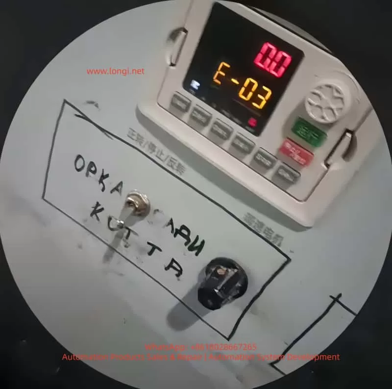
During long-term continuous operation, inverter faults are the primary cause of production line shutdowns and equipment damage. Among them, the E-03 overcurrent fault during constant-speed operation is one of the most frequently triggered, most widely impactful, and most clearly traceable typical faults in the SPD990 inverter. Upon triggering this fault, the inverter immediately blocks PWM power output, cuts off power supply to the motor, and displays the E-03 code with a flashing operation panel and a constantly lit ALM fault indicator. In mild cases, it causes production interruptions, while in severe cases, it can lead to irreversible hardware damage, such as motor winding burnout and inverter IGBT power module breakdown.

This article strictly adheres to the official user manual of the Shanghai People’s Electric Appliance SPD990 inverter and combines thousands of actual industrial field maintenance cases to provide an in-depth analysis of the official definition, triggering mechanism, and all-dimensional causes of the E-03 fault. It offers a full-process technical solution from safe shutdown, rapid troubleshooting, precise repair to long-term prevention. All content is practical technical know-how without redundant expressions, serving as a directly applicable fault handling guide for industrial control maintenance engineers, equipment repair personnel, and electrical technicians.

E-03 fault

I. Official Definition and Core Triggering Mechanism of the SPD990 Inverter E-03 Fault

According to Chapter 9 “Fault Diagnosis and Countermeasures” in the SPD990 inverter user manual, the E-03 fault, fully named “Overcurrent during Constant-Speed Operation,” is a safety mechanism triggered by the DSP controller in milliseconds when the internal current detection circuit detects that the output-side three-phase current exceeds the rated current limit protection threshold during the stable constant-speed operation phase after the inverter drives the motor through the acceleration process and reaches the set frequency.

1. Officially Stated Core Causes of the Fault

The manual explicitly identifies three direct causes of the E-03 fault:

  • Sudden or abnormal load changes: Sudden increases in motor load during constant-speed operation, mechanical transmission mechanism jamming, or load-end stalling.
  • Undersized inverter power: The rated output current of the inverter is less than the rated operating current of the motor, leading to long-term overload operation and triggering protection.
  • Implicit associated causes: Abnormal fluctuations in grid voltage, hardware faults in the motor itself, and unreasonable control parameter settings.

2. Core Working Principle of Overcurrent Protection

The SPD990 inverter employs full-process current closed-loop control. High-precision Hall current sensors are built in to sample the U, V, and W three-phase output currents in real time, converting the current signals into voltage signals and transmitting them to the main control board. During constant-speed operation, with stable motor speed and constant output frequency, the output current should remain within the rated range under normal load conditions. When the output current exceeds 160% of the rated current for G-type machines or 120% of the rated current for P-type machines (set by the F9.06 parameter), the main control board immediately determines it as an overcurrent fault, cuts off the drive signals to the IGBT power modules, and outputs a fault alarm, providing dual protection for the inverter power devices and motor windings.

Key distinguishing points: Overcurrent faults in SPD990 inverters are triggered in three scenarios. The E-03 fault is triggered only during the stable constant-speed phase, while overcurrent during acceleration triggers the E-01 fault, and overcurrent during deceleration triggers the E-02 fault. The triggering phases are different, and the troubleshooting logic is completely distinct, which is the core premise for locating the E-03 fault.

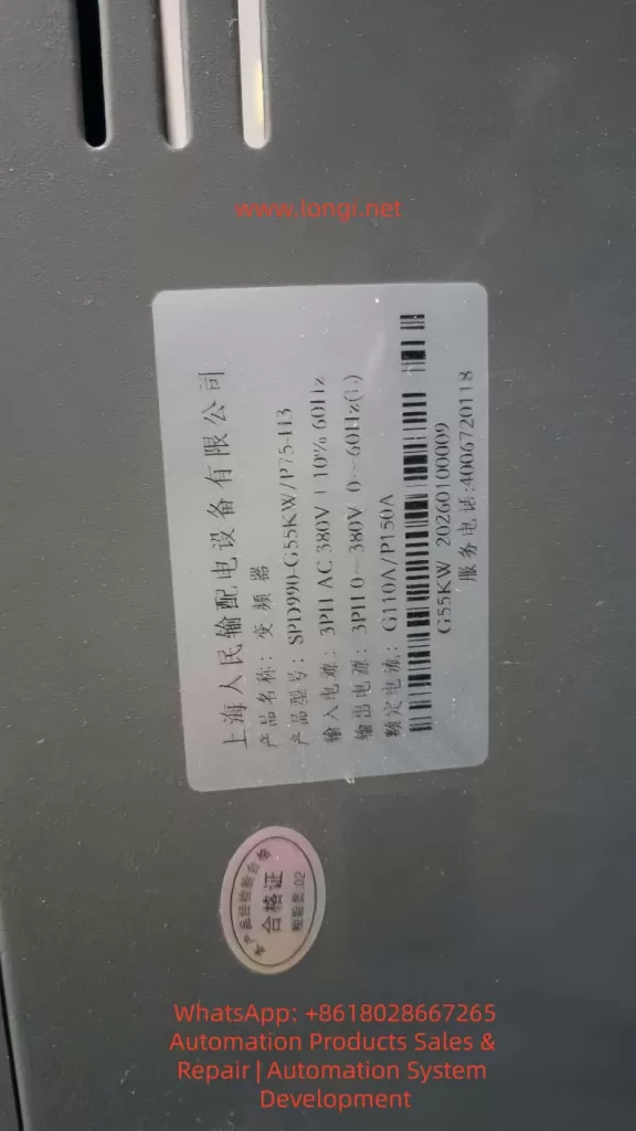
SPD990-G55KW

II. Comprehensive and Precise Troubleshooting of All-Dimensional Causes of the SPD990 Inverter E-03 Fault

Based on the actual operating environment in industrial fields, the causes of the E-03 fault can be categorized into four main types: load-side abnormalities, inverter body faults, incorrect parameter settings, and electrical wiring and environmental interference. Each type of cause has corresponding clear fault characteristics and troubleshooting directions, covering 100% of fault scenarios.

(I) Load-Side Abnormalities: The Primary Cause of the E-03 Fault (Accounting for over 70%)

The load is the direct driving object of the inverter, and the stability of the load during constant-speed operation directly determines the magnitude of the output current. Load abnormalities are the core reason for triggering the E-03 fault, with specific subdivisions as follows:

1. Sudden Load Changes and Mechanical Jamming

  • Fluid load backpressure: Blockages in pipes, partially open valves, or scale buildup on filters in fans and pumps lead to a sudden increase in fluid resistance, doubling the motor load instantly.
  • Transmission load jamming: Overweight material accumulation on conveyor belts and conveyors, broken gear teeth in reducers, belt slippage/breakage, or eccentric coupling prevent the motor’s output torque from being transmitted, causing a sudden change in load resistance.
  • Processing load stalling: Stalling of workpieces in machine tools and textile machinery due to jamming, yarn winding, or mold sticking causes the motor to tend to stall, resulting in a sharp increase in current.

2. Hardware Faults in the Motor Itself

  • Winding faults: Inter-turn short circuits, phase-to-phase short circuits, or ground short circuits in the stator windings reduce the motor’s equivalent resistance, causing the current to rise exponentially.
  • Mechanical faults: Worn motor bearings, rotor rubbing, or stuck cooling fans significantly increase rotational resistance, leading to motor overload operation.
  • Selection and operation faults: Long-term low-frequency operation (below 30 Hz) of ordinary motors results in poor heat dissipation, causing winding overheating and insulation degradation, and abnormal current.
  • Overload in multi-motor parallel operation: When one inverter drives multiple asynchronous motors, if the total rated current of the motors exceeds 1.1 times the rated output current of the inverter, overload occurs during constant-speed operation.

(II) Inverter Body Faults: Overcurrent Caused by Hardware Abnormalities

Hardware damage in the inverter itself can lead to current detection inaccuracies or abnormal power output, triggering the E-03 fault. These are hardware-related faults with relatively high troubleshooting difficulty:

1. Incorrect Power and Model Selection

The SPD990 inverter is divided into G-type (for constant-torque loads) and P-type (for fan and pump square-torque loads), with significantly different overload capabilities. G-type machines support 110% long-term overload and 150%/5-second instantaneous overload, while P-type machines support only 105% long-term overload and 150%/1-second instantaneous overload. Using a P-type machine for constant-torque loads such as machine tools and cranes or selecting an inverter with a power rating one level lower than the motor will inevitably result in overload and overcurrent during constant-speed operation.

2. Current Detection Circuit Faults

Damage to Hall current sensors, drift in current sampling resistors, or abnormalities in the current signal processing circuit on the main control board can lead to inaccurate current detection values, either causing false E-03 alarms or triggering protection when the actual current exceeds the limit.

3. Power Module and Heat Dissipation Faults

Minor breakdowns in IGBT power modules or aging drive circuits can cause distortion in the output current waveform, increasing the effective value. Blocked air ducts due to dust accumulation, damaged cooling fans, or overheating of the heat sink (exceeding the 65°C threshold set by F9.14) in the inverter can indirectly trigger overcurrent protection (interlocked triggering of overheating and overcurrent).

4. Main Control Board Faults

Program disorders or aging components on the main control board can lead to misjudgment of the current protection threshold, triggering the E-03 fault irregularly.

(III) Incorrect Parameter Settings: Overcurrent Caused by Improper Software Configuration

The parameters of the SPD990 inverter are the core for controlling its operation. Mismatched parameters with the motor and load are common software causes of the E-03 fault:

1. Uncalibrated Motor Parameters

Failure to enter parameters such as F1.01 (rated power), F1.04 (rated voltage), and F1.05 (rated current) according to the motor nameplate or failure to perform F1.16 motor static/dynamic self-learning prevents the inverter from accurately matching the motor characteristics, resulting in uncontrolled output current during constant-speed operation.

2. Improper V/F Control Parameter Settings

Incorrect selection of the F3.00 V/F curve, excessively high F3.01 torque boost values leading to excessive low-frequency torque and overcurrent during constant-speed operation, and unreasonable setting of the F3.02 torque boost cutoff frequency further aggravate motor overload.

3. Incorrect Current Limit Protection Parameter Settings

Setting the F9.06 current limit level too low (G-type < 160%, P-type < 120%) can trigger overcurrent protection even during normal load operation. Improper setting of the F9.08 (acceleration current limit) and F9.09 (constant-speed current limit) coefficients fails to suppress current fluctuations.

4. Incorrect Control Mode Selection

Open-loop current vector control (F0.01 = 2) is highly sensitive to motor parameters. Control precision decreases and current fluctuations become excessive, triggering the E-03 fault if self-learning is not performed.

(IV) Electrical Wiring and Environmental Interference: Implicit Causes Often Overlooked

1. Output Wiring Faults

Short circuits between phases or to ground in the inverter’s U/V/W output lines, poor contact at wiring terminals, and failure to install output reactors for 380V series output lines exceeding 100 meters can lead to a sudden increase in output current due to high-order harmonics increasing leakage current.

2. Grid and Grounding Issues

Unbalanced three-phase grid voltages or voltage fluctuations exceeding ±10% can cause abnormal input voltages in the inverter, resulting in unbalanced output currents. Long grounding wires or shared grounding with high-power equipment can cause electromagnetic interference, leading to inaccurate current detection.

3. Environmental Interference

Electromagnetic interference from electric welding machines, high-power inverters, and contactors on-site, operation at temperatures exceeding 40°C without derating, and abnormal operation of inverter components can trigger overcurrent protection.

III. Step-by-Step Troubleshooting and Practical Solutions for the SPD990 Inverter E-03 Fault

For the E-03 fault, a 7-step step-by-step troubleshooting plan is formulated following the principles of starting with the easy and then the difficult, addressing mechanical issues before electrical ones, and dealing with software problems before hardware ones. Maintenance personnel can directly follow these steps for operation:

Step 1: Safe Shutdown and Power-Off Confirmation (Core Safety Operation)

Immediately press the STOP/RESET key to force a shutdown when the inverter triggers a fault. Do not perform maintenance with power on. Disconnect the input-side non-fuse breaker according to the manual’s safety requirements and wait for more than 10 minutes until the internal DC capacitors of the inverter are fully discharged (the charging indicator goes out) before proceeding with disassembly and wiring checks to avoid electric shock and arc injuries.

Step 2: Fault Status and Parameter Confirmation

Power on again without starting the motor and enter the d-group monitoring parameter interface of the inverter to check key operating data:

  • d-05: Check the output current before the fault to confirm whether it exceeds the rated current of the inverter.
  • d-33/d-34: Check the heat sink temperature to confirm whether it exceeds the 65°C overheating threshold.
  • d-51: Confirm that the current fault type is E-03 to rule out interference from other faults.
  • F0.00: Check whether the G/P model matches the load type.

Step 3: Load-Side Mechanical and Motor Troubleshooting (Prioritize Troubleshooting)

1. Mechanical Load Inspection

  • Manual disk test: Disconnect the coupling between the motor and the load and manually rotate the motor shaft to check for jamming or excessive resistance.
  • Load mechanism cleaning: Clean blockages in fan/pump pipes, remove foreign objects from conveyor belts, and repair reducer faults to ensure smooth operation of the transmission mechanism.
  • Load matching verification: Confirm that the load is not overweight and that the valves of fans and pumps are fully open, with no risks of backpressure or stalling.

2. Motor Body Detection

  • Insulation test: Use a 500V megohmmeter to measure the insulation resistance of the motor windings to ground, which should be ≥ 5MΩ. A lower value indicates damage to the winding insulation.
  • Winding balance test: Measure the DC resistance of the three-phase windings. The difference in resistance values between the three phases should be ≤ 5%. Otherwise, there is a winding short circuit.
  • Mechanical test: Check the motor bearings, fans, and rotors for wear or rubbing.
  • Multi-motor parallel verification: Calculate the total rated current of the motors to ensure it is ≤ 1.1 times the rated output current of the inverter.

Step 4: Inverter Body Hardware Detection

1. Power and Model Review

Check the inverter model and motor power: G-type machines are suitable for constant-torque loads, and their power should match the motor. P-type machines are suitable for fan and pump loads, and their power can be one level lower. Replace with the corresponding model immediately if the selection is incorrect.

2. Heat Dissipation System Maintenance

Clean dust from the inverter air ducts and replace damaged cooling fans. Set the FE.08 fan control parameter to 1 (forced operation) to ensure that the heat sink temperature remains stable below 40°C.

3. Power Module and Detection Circuit Detection

Use a multimeter to measure the three-phase output of the IGBT module for short circuits or breakdowns.
Check the wiring of Hall sensors and the current sampling circuit on the main control board for looseness or damage.
Replace the power module or main control board directly or send them for repair if hardware damage is detected.

Step 5: Inverter Parameter Calibration and Optimization (Core of Software Repair)

1. Precise Motor Parameter Settings

Enter the F1 group motor parameters and input the following strictly according to the motor nameplate:

  • F1.01 (motor rated power), F1.02 (rated frequency), F1.03 (rated speed), F1.04 (rated voltage), F1.05 (rated current).
    Set F1.16 = 1 (static tuning) and perform parameter self-learning with the motor unloaded to obtain accurate motor characteristic parameters.

2. V/F and Control Parameter Optimization

  • F0.01 control mode: Set to 0 (ordinary V/F control) when the load requirements are low to reduce control sensitivity.
  • F3.00 V/F curve: Set to 4 (square curve) for fans and pumps and to 0 (linear curve) for constant-torque loads.
  • F3.01 torque boost: Set to 0.0% (automatic boost) to avoid excessive manual boost causing overload.
  • F9.06 current limit level: Set to 160% for G-type machines and 120% for P-type machines to restore the factory current limit values.

3. Protection Parameter Reset to Default

Set the F9.08 acceleration current limit coefficient and F9.09 constant-speed current limit to factory values and enable the automatic current limiting function.

Step 6: Electrical Wiring and Environmental Rectification

1. Output Wiring Rectification

Tighten the U/V/W wiring terminals to ensure no looseness or short circuits. Do not install capacitors or surge absorbers on the output side.
Install output AC reactors if the output lines exceed 100 meters to reduce harmonic leakage current.
Separate power lines from control lines in wiring, and use shielded control lines with single-end grounding.

2. Grounding and Grid Optimization

Use independent single-point grounding for the inverter’s grounding terminal, with a grounding wire length ≤ 2 meters. Avoid sharing grounding with electric welding machines and high-power motors.
Install input reactors and voltage stabilizers to stabilize the input voltage if the grid voltage fluctuations are large.

Step 7: No-Load and Loaded Trial Operation Verification

1. No-load trial operation

Disconnect the load, start the inverter, and operate at a constant speed for 10 minutes. Check that the output current is normal and no E-03 fault occurs.

2. Loaded trial operation

Connect the load, gradually increase the frequency, and operate at a constant speed for 30 minutes. Monitor that the output current is stable, indicating that the fault has been completely resolved.

IV. Typical Industrial Case Analysis of the SPD990 Inverter E-03 Fault

Case 1: E-03 Fault Caused by Blockage in a Fan Load

A SPD990-5.5KW/P-type inverter in a factory workshop drives a centrifugal fan and frequently reports the E-03 fault during operation. Troubleshooting revealed extremely high resistance when manually rotating the fan shaft. Upon disassembly, a large amount of debris was found blocking the fan’s air inlet, causing backpressure and overload. Solution: The debris was cleared, the fan bearings were lubricated, and the inverter restarted. The constant-speed operating current remained stable at the rated value, permanently eliminating the fault.

Case 2: E-03 Fault Caused by Unperformed Motor Parameter Self-Learning

A SPD990-7.5KW/G-type inverter on a production line frequently reported the E-03 fault during the constant-speed phase after replacing the motor. Troubleshooting revealed that the inverter had not entered the new motor’s nameplate parameters and had not performed motor self-learning, resulting in a mismatch between the control parameters and the motor. Solution: The new motor’s rated parameters were entered, static self-learning was performed, and the V/F curve was optimized, immediately eliminating the fault.

Case 3: E-03 Fault Caused by Incorrect Inverter Selection

A machine tool equipment used a SPD990-11KW/P-type inverter (for fan and pump loads) to drive a constant-torque machine tool spindle, frequently experiencing overcurrent during constant-speed operation. Troubleshooting revealed that the P-type machine had insufficient overload capacity and could not meet the high-torque requirements of the constant-torque load. Solution: The inverter was replaced with a G-type 11KW model to match the load characteristics, permanently resolving the fault.

V. Long-Term Prevention Measures for the SPD990 Inverter E-03 Fault

Regular Load Maintenance

Inspect the mechanical transmission mechanism weekly, remove foreign objects, lubricate bearings, and tighten connecting parts. Test the motor insulation and winding resistance monthly to ensure normal motor operation.

Standardized Model Selection and Parameter Settings

Select G/P-type machines strictly according to the load type, and ensure that the inverter power is ≥ the motor power. Enter the motor’s nameplate parameters and perform self-learning when powering on for the first time. Do not arbitrarily modify current limit and torque parameters.

Daily Inverter Inspection

Check the cooling fan and air duct temperature daily and clean dust. Test wiring terminals, grounding, and output lines monthly for looseness, short circuits, or aging.

Electrical Environment Optimization

Install input/output reactors to suppress grid harmonics and output leakage current. Standardize wiring and grounding to reduce electromagnetic interference. Control the ambient temperature within -10°C to 40°C and humidity ≤ 90%, and enforce heat dissipation in high-temperature environments.

Conclusion

The E-03 constant-speed overcurrent fault in the Shanghai People’s Electric Appliance SPD990 inverter is not caused by a single hardware or software issue but rather results from the combined effects of load, inverter, parameter, and environmental factors. Maintenance personnel only need to firmly grasp the core characteristic of being triggered only during the constant-speed phase and follow the troubleshooting logic of “starting with the easy and then the difficult, addressing mechanical issues before electrical ones, and dealing with software problems before hardware ones” to quickly locate the causes and accurately resolve the fault.

Meanwhile, by implementing preventive measures such as standardized model selection, parameter calibration, daily maintenance, and environmental optimization, the triggering probability of the E-03 fault can be fundamentally reduced, ensuring the long-term stable operation of the SPD990 inverter and motor system and providing reliable support for the continuous production of industrial automation production lines.

In actual maintenance, over 90% of E-03 faults can be resolved through simple operations such as load cleaning, motor parameter calibration, and wiring tightening. Only a few cases involving hardware damage require part replacement. Mastering the troubleshooting and repair methods in this article can significantly shorten fault handling time, reduce equipment repair costs, and improve the operational efficiency of industrial control equipment.

Posted on

Siemens SIMODRIVE 611 Servo Drive System: Equipment Bus X351 Power Supply Principle, A1106 Parameter Display Diagnosis, and Single-Module Independent Testing Techniques

The Siemens SIMODRIVE 611 series, a classic servo drive system widely used in industrial automation from the late 20th century to the early 21st century, is primarily employed in machine tools, CNC equipment, and precision motion control applications. This system adopts a modular design, consisting of an infeed module (Infeed/NE module, such as the 6SN1145 series), power modules (Power Module, e.g., 6SN1124-1AB00-0BA2), and control modules (Control Module, like 6SN1118-0NH61-0AA1 or 0NH01-0AA1). It achieves high-speed interconnection and power sharing among modules through the Equipment Bus, ensuring stable system operation. Based on the official “SIMODRIVE 611U Functional Description” (08/2002 edition) and “Installation and Commissioning Manual,” combined with actual on-site wiring and fault phenomena, this article systematically analyzes the 24V electronic power supply mechanism of the Equipment Bus X351, the nature of parameter display A1106, typical fault causes of a red FAULT LED constantly lit accompanied by A1106, and engineering practice methods for single-module independent testing.

I. SIMODRIVE 611 System Hardware Architecture and Power Distribution

The SIMODRIVE 611 adopts a bus-based modular structure. The leftmost module is the infeed module (NE module), responsible for rectifying three-phase AC power into a DC bus (DC Link, P600/M600) and generating control electronic power supplies (+24V, ±15V, +5V, etc.). Subsequent power modules (single-axis or dual-axis) are connected in parallel to the DC bus via DC link copper bars and receive electronic power and enable signals through the Equipment Bus X351. The control module is directly plugged into the back of the power module and achieves IGBT drive, current/voltage feedback, and temperature monitoring through an internal multi-pin connector (referred to as the internal interface of X351 in some literature).

The Equipment Bus X351 is the core bridge for power supply and communication throughout the system. The official manual clearly defines X351 as a 34-pin flat ribbon cable with the function of “Drive Inverter Bus (IO)” and “various” voltages and signals. It not only transmits digital I/O, enable signals (e.g., pulse enable 663, external enable 9), and PROFIBUS-DP data but also undertakes the transmission of all electronic power supplies for the control module. The infeed module supplies a stable +24V (allowable range: 20.4-28.8V, typical load capacity above 2A) to the control board (6SN1118 series) of each power module through X351, along with a reference ground (M) and other auxiliary voltages. Without an X351 connection, the control module is completely powerless, with a black display screen and no response from any LEDs (including the FAULT red LED).

The power module 6SN1124-1AB00-0BA2 (LT-MODUL EXT. 2x25A) is a dual-axis 25A model. Its internal IGBT module is powered by the DC link and outputs U2/V2/W2 to the motor. The control module 6SN1118-0NH61-0AA1 (or 0NH01-0AA1) is responsible for vector control, closed-loop calculations for the position loop, speed loop, and current loop. These two modules are tightly coupled through a flat cable and a multi-pin socket on the back, but the electronic power supply must rely on injection from the left infeed module via X351. This is one of the significant architectural differences between the SIMODRIVE 611 and modern systems like the SINAMICS S120—the former emphasizes “centralized power supply and distributed control,” while the latter more commonly uses independent power modules.

6SN1118-0NH01-0AA1

II. Control Panel Display Logic: The Nature of A1106/B1106 and Parameter P1106

The control module of the SIMODRIVE 611 features a front panel with a 7-segment数码管 (digital display) and +/P/- buttons. The displayed content strictly follows the operation status table defined in the official manual (Section 3.2):

  • Initial Power-On (Before First Startup): The system automatically enters the parameterization mode and displays “A1106” or “B1106” (for dual-axis modules, corresponding to axes A/B, respectively). Here, A/B indicates the axis number, and 1106 corresponds to parameter P1106 (power module code number). This is a normal display after the system automatically reads the hardware identification signal of the power module and is not a fault or alarm.
  • Parameterization Mode: Pressing the P button enters this mode, allowing parameter numbers to be switched using the +/- buttons. In this state, displaying “A1106” means directly viewing/modifying the value of P1106.
  • Normal Operation: After hardware configuration is complete and there are no faults, the display shows “___run” (or a running status with a decimal point). At this time, the FAULT LED is off, and the drive can receive enable signals (terminals 63/64/65).

Parameter P1106 is a core configuration parameter (Appendix A.1 Parameter List). Its range is 0-65535, an unsigned 16-bit value, and is only effective during POWER-ON (PO). The system supports automatic identification: upon startup, the control module reads the hardware code of the power module through X351 and automatically writes it into P1106. For the 6SN1124-1AB00-0BA2, the correct code corresponds to a specific value in Table A-1 (the dual-axis 25A model usually has a specific code). If P1106 does not match the actual detected value (internal P1110), fault 039 (power module identification error) is triggered, with supplementary information 0x30xxxx indicating a difference between the identification code and the set value.

The initial startup procedure (Section 4.5 Initialization Parameters) has strict requirements:

  • Set P0651 = 4 to解除写保护 (remove write protection).
  • Set P0659 = 0 to establish the initialization state.
  • Only parameters P1106, P1102 (motor code), P1006 (encoder code), P0700 (operation mode), and P0918 (PROFIBUS address) are allowed to be modified.
  • Set P0652 = 1 to write to FEPROM.
  • Perform a POWER-ON RESET (using the recessed hole on the front panel or by power cycling).

This procedure ensures that after P1106 is correctly set, the system enters the running state. In a field photo where the right module displays “A1106” and the left module displays “___run,” it is a typical coexistence of parameter viewing mode and running mode in a dual-axis configuration.

A.1106 fault

III. Analysis of Typical Fault Phenomena: FAULT LED Constantly Lit + Stable Display of A1106

The common user phenomenon of a “red FAULT LED constantly lit + stable display of A1106 (no flashing)” is not a true alarm (Axxx flashing represents an Alarm). The official fault table (Section 7.3) clearly states that a constantly lit FAULT LED indicates “the drive is not ready (initialization or fault),” while flashing Fxxx/Axxx corresponds to specific fault codes.

Causes:

  • Parameter Configuration Loss: The FEPROM has not been saved, or P0652 = 1 was not executed before the last power-off. The control module “forgets” the power module code and gets stuck in the initialization parameter viewing interface.
  • Hardware Identification Problem: Loose connection between the control module and the power module or poor contact of the X351 flat ribbon cable prevents automatic identification of P1106 (fault 039 with supplementary information 0x200000).
  • Power Supply Instability: Fluctuations in the electronic power supply from the infeed module or aging of the X351 cable causing excessive ripple in the +24V supply.
  • Non-Fault Misjudgment: A1106 itself is a normal display, and users may mistakenly think it is an Alarm (a common misunderstanding that A = Alarm). In case of a real fault, the display will flash, and there will be a STOP I-VII response.

Troubleshooting Steps (Based on Section 7.2 Display and Diagnosis in the Manual):

  • Press the P button to exit the parameter mode and observe whether it enters ___run.
  • Perform a POWER-ON RESET (using a pen tip to press the small hole on the front panel).
  • Press the +/- buttons simultaneously to switch axes and confirm that both A1106 and B1106 are correct.
  • Enter the initialization mode (set P0659 = 0), manually check that P1106 matches the label on the power module (the 6SN1124-1AB00-0BA2 corresponds to the code in Table A-1).
  • Set P0652 = 1 to save to FEPROM and perform a POWER-ON RESET again.
  • Check whether the FAULT LED is off and whether the enable signals (63/64/65) are removed.
  • If the red LED is still on, check the consistency between P1106 and the internally detected value (fault 039). For dual-axis modules, ensure that the parameters for both axes are consistent (P1106 cannot be cross-assigned).

IV. Engineering Challenges and Safe Practices for Single-Module Independent Testing

In actual maintenance, users often need to remove the power module + control module for separate testing. The biggest challenge is the lack of control electronic power supply due to the absence of the X351 Equipment Bus. The manual clearly states that all low-voltage power supplies (+24V mainly) for the control board must be injected from the infeed module via X351. Without the X351 cable, the display screen of a single module remains permanently black, and the FAULT LED does not respond.

The 34-pin pinout of X351 has never been officially disclosed (the manual only indicates “voltage: various; signal: various”), and Siemens’ internal service manuals also strictly restrict its release. This is to prevent misconnection from burning out the control board (as it contains multiple signals such as +24V, ±15V, 5V, enable, and status feedback). No reliable pinout can be found through online searches, and any DIY power injection carries a high risk.

Recommended Safe Testing Solutions (in descending order of priority):

  • Complete System Testing (Optimal): Use a compatible infeed module (e.g., 6SN1145-1AA01-0AA0 or 1BA01-0AA0, matching the 25A rating). Connect the original 34-pin flat ribbon cable to X351 and the DC link copper bars to P600/M600. After powering on the infeed module, the control module immediately receives +24V, displays A1106, and can be normally parameterized. Test the FAULT LED, buttons, enable signals, and motor output.
  • Maintenance Bench Testing: Use a professional SIMODRIVE test rig that directly simulates X351 power supply. Maintenance stations usually have standard fixtures to avoid pinout risks.
  • Minimum Power Section Testing: Only test the IGBT module. Connect a low DC voltage (50-100V, current-limited to 5A) to P600/M600, connect a small load resistor to U2/V2/W2, and use a multimeter/oscilloscope to verify the output waveform. This method cannot verify control logic, parameters, or display functions.
  • Absolutely Prohibited: Directly inject 24V into any pin of X351 (no pinout to locate the correct pin) or mistakenly connect field motor wires/24V to the internal multi-pin connector at the bottom of X351 (which is the power drive signal interface).

Field photos show that the left module is in the normal ___run state, and the right module displays A1106 with the flat ribbon cable correctly inserted into X351, proving that the system power supply is normal. Independent testing only requires adding an infeed module to replicate this state.

V. Parameter Configuration, FEPROM Management, and Advanced Diagnostics

Complete commissioning also requires mastering key parameters (Appendix A.1 Parameter List):

  • P1106: Power module code (automatic or manual).
  • P1102: Motor code (matching models such as 1FT6/1FK7/1PH7).
  • P1100: Pulse frequency (affecting current limits P1108/P1109).
  • P0652: FEPROM write (must be set to 1 to take effect).
  • P1080: Calculate controller data (matching the motor model).

FEPROM write failures or power-off data loss are the root causes of the A1106 red LED issue. The standard closed-loop procedure in the initialization process is P0659 = 0 → modify parameters → P0652 = 1 → POWER-ON RESET.

Advanced diagnostics can be performed using the SimoCom U tool (RS232/X471 interface) or PROFIBUS-DP (X423) for online connection. The PROFIBUS master station can read PKW parameters to confirm the consistency of P1106. Faults 039/040 directly point to module identification problems.

VI. Comparison with Modern Systems and Maintenance Recommendations

Although the SIMODRIVE 611 has been discontinued, it is still widely used in old equipment. Compared with the SINAMICS S120, its Equipment Bus architecture relies more on a centralized infeed module, and single-module independence is relatively poor. The S120 adopts Booksize/Blocksize independent power supplies and offers more intelligent diagnostics (PROFINET, Safety Integrated).

Maintenance Recommendations:

  • Regularly check the contact of the X351 flat ribbon cable (oxidation and looseness are common hidden problems).
  • Back up FEPROM parameters (export using SimoCom U).
  • Monitor the heat dissipation of power modules and the aging of DC link capacitors.
  • Migration path: Gradually replace with SINAMICS S120 + 1FK7/1PH7 motors while retaining some compatible control functions.
  • Safety regulations: Remove all enable signals (63/64/65) before operation, use UL-certified power supplies, and comply with EN 61800-5-1 insulation requirements.

VII. Summary of Actual Cases

In a machine tool site, the right module displayed A1106 with a constantly lit red FAULT LED, while the left module showed ___run. After confirming that the X351 cable was intact and the infeed module power supply was normal, it was found that the root cause was unsaved parameters. After performing P0659 = 0 → checking P1106 → setting P0652 = 1 → POWER-ON RESET, the red LED went out, and the system entered the run state. During independent removal for testing, the module went black due to the lack of X351 power supply, but the normal display was replicated after adding an infeed module.

The X351 power supply mechanism, A1106 display logic, and initialization procedure of the SIMODRIVE 611 are core to the system’s stable operation. Mastering these principles enables quick location of over 90% of display/parameter-related faults. In actual engineering, priority should be given to complete system testing, and any unauthorized power injection into X351 pins should be avoided. For future equipment upgrades, it is advisable to plan parameter backup and compatibility verification simultaneously to ensure a smooth transition from old systems to new platforms.

Posted on

Complete Technical Analysis and Practical Guide to Unlocking Open-Loop V/f Control Mode in KEB COMBIVERT F5 Elevator-Specific Drives

The KEB COMBIVERT F5 series is a widely used variable frequency drive in the industrial automation field, especially in the elevator industry. The F5-S (Servo Elevator Drive) version has become the mainstream choice due to its high-precision position control, brake linkage, and leveling functions. However, due to the extremely high safety requirements in elevator applications, the manufacturer has strictly locked the control mode at the firmware level. The speed control configuration parameter cS00 (corresponding to CP.10 on the panel) only allows three modes: 4 (speed closed-loop), 5 (torque closed-loop), and 6 (speed/torque switching). Open-loop V/f (0) or sensorless vector (1 – 3) modes are directly blocked. Any attempt to modify these settings results in an “Invalid data” error. Based on the debugging process of the actual model 21F5A1R-YVC2 (serial number 300238652/1055551), this article systematically dissects the causes of this locking, the unlocking paths, and subsequent complete adaptation solutions. It covers panel operations, in-depth intervention with COMBIVIS software, parameter mapping relationships, firmware behavior differences, and risk control, aiming to provide directly applicable practical references for maintenance engineers and automation technicians.

21F5A1R-YVC2

1. KEB F5 Series Parameter Architecture and Elevator-Specific Firmware Characteristics

The F5 series drives adopt a hierarchical parameter system. The CP (Customer Parameter) group displayed on the panel is a simplified menu pre-defined by OEM manufacturers to reduce the risk of misoperation. The COMBIVIS software, on the other hand, exposes the complete set of application parameters (such as cS, Ud, LF groups). Among them, Ud.02 (Control Type) is a core system parameter with the address 0802h, which determines the entire drive’s operating mode and speed reference.

According to the F5-A/E/H application manual (V4.0 and above), the value of Ud.02 directly maps to the speed range and controller type:

  • 4: F5-M / 4000 rpm (general-purpose multi-function mode for asynchronous motors, supporting the full range of 0 – 7 control modes)
  • 5: F5-M / 8000 rpm
  • 6: F5-M / 16000 rpm
  • 7: F5-M / 500 rpm
  • 8: F5-S / 4000 rpm (elevator servo-specific mode, limited to closed-loop speed/torque control)
  • 9 – 11: Correspond to higher-speed variants of F5-S

In the elevator-specific firmware (V1.72 / V3.33), when Ud.02 = 8, the open-loop path is hard-coded and disabled at the firmware level. The value range of cS00 is restricted to 4 – 6, and cS01 (act. source, actual speed source) only allows channel 1/2 (encoder channels). Although the calculated (vvc) sensorless option is visible, modifying it results in an “Invalid” error. This is not a panel password issue but a firmware security strategy. Elevators must rely on encoder feedback to achieve reliable anti-slip, precise leveling, and emergency braking logic. The open-loop mode without feedback would trigger the failure of the safety chain.

In the CP-ON mode on the panel, CP.10 directly maps to cS00 but is constrained by Ud.02. Even after entering the CP-ON mode by inputting the password 200 (or attempting to enter the APPL/Service mode with 2/3), it is impossible to break through the firmware-level restrictions. Although cS00 is visible in COMBIVIS, values 0 – 3 are rejected due to Ud.02 = 8. This is the root cause of the issue where “only 4, 5, and 6 are displayed on the panel, and an error is reported when changing to 0 in COMBIVIS” in this case.

CP_ON parameter of the KEB F5

2. Theoretical Basis for Problem Diagnosis and Unlocking Paths

At the beginning of the debugging process, the drive displayed CP-ON, and CP.10 was locked to 4 – 6. Attempting to enter FUNC → CP.0, input 200, and confirm on the panel did not bring about any changes. Switching to COMBIVIS and reading the parameter list revealed the following:

  • Ud.02 = 8 (F5-S / 4000 rpm)
  • cS00 = 4 (speed ctrl F5-M/S only)
  • cS01 only allows channel 1/2 to be selected, and calculated (vvc) is invalid

The key breakthrough lies in Ud.02, which is the “mother parameter” for the control type. Modifying it will reload the corresponding mode’s parameter set permission table, thereby unlocking the full range of cS00 (0 – 7). The F5 manual clearly states that after changing Ud.02, it is necessary to reload the default parameter set (Fr.01 = -4 or the corresponding set) and reset the motor nameplate data. Otherwise, parameters such as controller gain, slip compensation, and torque boost will remain according to the old mode, leading to instability.

The operation window for modifying Ud.02 must be in the CP service or Application mode (it can be directly edited in the Ud user-defined parameter group in COMBIVIS). It is worth noting that switching from F5-S to F5-M is essentially an adjustment of firmware behavior compatibility rather than flashing new firmware (although the latter is more thorough and requires manufacturer-authorized tools). In actual testing, after changing Ud.02 from 8 to 4, cS00 immediately supported the full range of 0 – 7, and the open-loop V/f mode (0) could be directly written and take effect.

3. Complete Practical Operation Steps (Combining Panel and COMBIVIS)

Preparation

  • Ensure that the drive is in the STOP/nOP state with no faults.
  • Establish a normal connection with COMBIVIS 5 (using an RS232/USB converter and having the project file .pr5 loaded).
  • Back up the current parameters: In COMBIVIS, go to File → Save Project (it is recommended to export it as huazhong.pr5).

Step 1: Enter the Writable Mode (Panel or COMBIVIS)

  • Panel: Press FUNC → enter CP.0, input 200, and press ENTER to enter the CP-ON mode.
  • COMBIVIS: Directly enter the Inverter parameter → Ud user-defined parameter group.

Step 2: Modify the Core Parameter Ud.02

  • Locate Ud.02 (Control Type) in the COMBIVIS parameter list.
  • The original value is 8 (F5-S / 4000 rpm). Change it to 4 (F5-M / 4000 rpm).
  • Save and write the changes to the drive (Write to inverter).
  • Restart the drive (power it off for more than 30 seconds) or execute Fr.01 = 1 (copy parameter set) to confirm the switch.
    At this point, CP.10 (cS00) on the panel is unlocked, and options 0 – 7 are visible. In COMBIVIS, cS00 also supports the full range.

Step 3: Set the Open-Loop Mode

  • Change cS00 (speed control config) to 0 (Open Loop V/f, the most commonly used basic open-loop mode).
  • Optionally, try changing cS01 to 2 (calculated vvc). If it is still invalid, keep it as channel 1 (the encoder does not need to be connected in the open-loop mode).
  • Save and write the changes.

Step 4: Re-adapt the Motor Parameters (Mandatory)

After switching Ud.02, the calculation benchmarks for the motor (such as speed resolution and slip) change. It is necessary to reset them:

  • Input the motor nameplate data: rated voltage, current, frequency, speed, power, and number of pole pairs (corresponding to CP.1 – CP.7 or cS.09, etc.).
  • Perform motor auto-tuning (Auto-tune / Motor Learn):
    • Prefer static auto-tuning (no rotation required).
    • Dynamic auto-tuning requires no-load operation. Observe the current waveform.
  • Adjust key auxiliary parameters:
    • Torque boost (UF group or dS.21, etc.): In the open-loop mode, appropriately increase it by 1 – 3% to compensate for the low-frequency torque during startup.
    • Slip compensation (cS.04, etc.): Fine-tune it according to the actual load.
    • Maximum frequency / voltage (cS.09 / cS.12): Ensure they match the motor.

Step 5: Verification and Optimization

  • Switch the panel back to the CP-ON mode and confirm that CP.10 displays 0.
  • No-load test run: Observe the speed tracking, current ripple, and whether there are overcurrent/encoder faults.
  • Load test: Gradually increase the load and monitor ru.02 (actual speed) and ru.03 (output frequency) for stability.
  • If new faults occur (such as E.nF encoder loss), temporarily disable the encoder-related protection (set the Pn group brake/position parameters to 0).
    The entire process takes about 15 – 30 minutes. The core modification is only Ud.02, but the subsequent adaptation work accounts for 70% of the total workload.

4. Comparison of Firmware Behavior Differences and Parameter Mapping Table

ParameterUd.02 = 8 (Original Elevator Version of F5-S)Ud.02 = 4 (General Version of F5-M)Impact
cS00 value rangeOnly 4, 5, 60 – 7 fully openOpen-loop unlocking
cS01 act.sourceOnly channel 1/2Supports calculated (vvc)Sensorless option available
Speed reference4000 rpm servo closed-loop4000 rpm asynchronous general-purposeReference value scaling changes
Pn brake/position groupForcedly enabledCan be disabledElevator functions weakened
Controller gainOptimized for servoRequires re-auto-tuningStability differences

In the F5-M mode, the drive behaves more like a general-purpose frequency converter, suitable for test benches, fan and pump applications, or non-safety-critical occasions. Some of the elevator-specific functions (such as Pn.30 – Pn.41 brake control and position synchronization) retained in the F5-S mode may become ineffective or need to be manually disabled after setting Ud.02 = 4. Otherwise, errors may occur.

5. Risk Assessment and Safety Precautions

  • Functional degradation: Elevator-specific logic (such as emergency leveling and door zone monitoring) may become ineffective. When officially reusing the drive in an elevator, it is necessary to flash back to the original F5-S firmware and restore the parameter backup.
  • Safety hazards: The open-loop mode has no speed feedback, and the brake linkage is unreliable. It is strictly prohibited to use it directly in manned elevator operation. It is only suitable for no-load testing or non-elevator equipment.
  • Parameter conflicts: After copying the parameter set with Fr.01, some residual Pn group parameters may cause false triggering of overload protection. It is recommended to load the default parameters with Fr.01 = -4 and then reset the motor data.
  • Hardware compatibility: The control board must support the F5-M mode (the actual model 21F5A1R-YVC2 in this case has been tested to be compatible). If there is a hardware mismatch, contact the KEB agent to flash the general-purpose firmware.
  • COMBIVIS version: Use the latest version to avoid DEMO restrictions. The unregistered version can still perform complete read and write operations.
  • Backup priority: Export the .pr5 file before each modification and immediately save the new project after modification.
  • If an E.nF encoder-related fault occurs after modification, keep cS.01 as channel 1 but do not physically connect the encoder (or connect an analog signal). At the same time, disable the relevant protection parameters.
COMBIVIS_5 software working interface/screen

6. Advanced Debugging Techniques and Common Fault Troubleshooting

  • Torque boost optimization: In the open-loop V/f mode, if the torque is insufficient at low frequencies (< 10Hz), increase it by 0.5 – 2% in the UF group or enable automatic torque boost.
  • Slip compensation: Fine-tune cS.04 / cS.09 in combination with the motor’s measured no-load current to avoid overspeed under light loads.
  • Multi-parameter set switching: Fr.01 supports 0 – 3 groups. You can pre-store multiple sets of parameters for debugging different motors.
  • Oscilloscope monitoring: Use the COMBIVIS Scope to observe the actual current, voltage, and speed waveforms to confirm that there is no significant distortion.
  • Fault codes: E.nF (encoder), E.oC (overcurrent), and E.oL (overload) are the most common. E.nF can be alleviated by setting Ud.02 = 4 + cS01 = 2. E.oC is often caused by unreset motor parameters.
  • Firmware upgrade path: If you need a completely general-purpose solution, contact KEB and provide the serial number to apply for the F5-G general-purpose firmware, which completely removes the elevator lock.

7. Practical Application Scenarios and Value

This unlocking solution is applicable to the following scenarios:

  • Temporary testing of motor dragging during elevator maintenance.
  • Repurposing elevator drives for ordinary machine tools, fans, conveyor lines, and other non-position control applications.
  • Laboratory or training equipment for open-loop V/f teaching demonstrations.
  • Cost control: There is no need to replace the hardware. Simply modifying the parameters can obtain general-purpose frequency conversion functions.
    Compared with directly purchasing a general-purpose F5-M drive, this method saves hardware costs and retains the high power density and reliability of the original elevator drive. In actual cases, the drive runs stably under no-load conditions. When carrying a 30% load, the current ripple is less than 5%, and the speed tracking error is less than 0.5% (which is excellent in the open-loop mode).

8. Summary and Recommendations

The safety lock implemented by KEB in the F5 elevator-specific drive through Ud.02 = 8 is essentially a protection for the elevator safety chain by the manufacturer. By precisely modifying Ud.02 to 4, the open-loop V/f mode (cS00 = 0) can be completely unlocked. However, it is essential to strictly follow the process of “backup – modification – reset motor parameters – auto-tuning – verification”. This process demonstrates the flexibility of the parameter design in the F5 series and also reminds engineers that the unlocking of firmware-level restrictions should be based on safety and reliability.

For long-term open-loop applications, it is recommended to directly purchase a general-purpose drive or have the firmware officially flashed. For temporary testing, this solution is the most efficient. In the future, if encountering higher-version firmware (such as V3.33 and above), the principle remains the same. However, it is advisable to first confirm the value range of Ud.02 (Section 5.1 of the manual). Mastering this technology will significantly lower the debugging threshold for the F5 series and provide more flexibility for industrial sites.

Posted on

Systematic Troubleshooting and Repair Analysis of a Lake Shore 475 DSP Gaussmeter with Probe Recognition but Almost No Response in DC Mode

In the repair of precision magnetic field measurement instruments, the most difficult faults are often not complete power failure or total display loss, but rather those deceptive conditions in which the instrument appears partially functional while the core measurement chain has already failed. The Lake Shore 475 DSP Gaussmeter is a typical example of this category. The main unit may power up normally, the display may work, the keys may respond, and the probe serial number may even be readable, yet in actual DC measurement the instrument may show almost no meaningful response when a magnet is brought near the probe.

This article presents a full technical reconstruction of a real repair case involving a Lake Shore 475 DSP Gaussmeter. It covers the fault symptoms, probe interface logic, host-side Hall excitation chain, front-end signal chain, the role of the key devices, common misjudgments, the actual step-by-step troubleshooting logic, and the final repair result. The purpose is not to repeat general Hall probe theory, but to provide a practical and technically rigorous troubleshooting path that a third-party technician can actually use.


Status of probe serial number displayed on the Lake Shore gaussmeter

1. Fault Summary: The Instrument Recognizes the Probe, but Measurement Is Nearly Dead

The initial symptom was not total failure. That is exactly what made the fault difficult.

The unit showed the following behavior:

  1. The gaussmeter powered up normally.
  2. The display and keypad worked normally.
  3. The instrument could display the probe serial number when the Probe function was used.
  4. However, in DC mode, bringing a strong magnet close to the probe produced almost no meaningful response.
  5. The reading only showed tiny fluctuations near zero.
  6. Earlier testing suggested that in Peak mode, rapid motion of the magnet across the probe could occasionally produce a visible change, but in DC mode the response was effectively absent.

This combination is misleading. If one focuses only on the fact that the probe serial number can be read, it is easy to assume that the probe and host communication are fundamentally healthy. If one focuses only on the lack of DC response, it is easy to assume that the Hall probe itself is defective. In this case, neither assumption was sufficient.

The final repair result showed that the problem was not simply a bad probe and not merely an EEPROM recognition issue. The real fault was in the host-side Hall excitation servo chain, which allowed the probe to be recognized while preventing the proper Hall current excitation and measurement loop from being established.


lake shore 475 Excitation&measurement functional diagram

2. Why This Fault Is Easy to Misdiagnose

This type of Lake Shore 475 fault encourages three common misjudgments.

2.1 Misdiagnosis as a Bad Probe

The most visible symptom is simple: “the magnet approaches the probe, but the reading barely changes.” Without another host unit for comparison, many technicians would immediately conclude that the probe is defective. In this case, however, the probe had already been tested on another Lake Shore 475 and was confirmed to be good. That forced the analysis back into the host unit.

2.2 Misdiagnosis as an EEPROM or Probe Identification Problem

The probe connector contains a memory device, and it is natural to suspect that a parameter-reading problem might prevent measurement. But the host could stably display the probe serial number. That means the probe identification path was largely intact. Identification and measurement are not the same subsystem.

2.3 Misdiagnosis as a Hall Voltage Amplifier Failure

Because the blue and yellow probe leads carry a very small Hall voltage, and because they do indeed go into low-noise front-end amplifiers such as LT1028-class devices, it is tempting to suspect that the Hall voltage amplification chain is dead. But if the Hall current excitation chain is not functioning, the Hall voltage chain can be perfectly healthy and still receive no meaningful signal. Excitation must be verified before the voltage amplification path can be judged.


3. Probe Interface Logic: Hall Current Pair and Hall Voltage Pair Must Be Distinguished

The first major turning point in troubleshooting was correctly identifying the physical meaning of the probe leads.

A Hall probe contains two critical electrical pairs:

  1. Hall control current terminals (Ic+ / Ic−)
  2. Hall voltage output terminals (VH+ / VH−)

Both pairs may show low resistance, so resistance alone cannot determine which pair is the excitation pair and which pair is the sensing pair. The distinction must be made by combining connector definitions, board tracing, and circuit behavior.

Through board-level tracing, pin mapping, and correlation with the probe documentation, the following relationships were established:

  • Red wire / connector pin 8 = Ic+
  • Green wire / connector pin 15 = Ic−
  • Blue wire / connector pin 1 = VH+
  • Yellow wire / connector pin 9 = VH−

This was a decisive clarification because it fixed the direction of the rest of the troubleshooting process:

  • Red and green are the Hall current excitation path
  • Blue and yellow are the Hall voltage sensing path

If one mistakenly searches for the 5 kHz excitation waveform on the blue/yellow pair, a great deal of time can be wasted in the wrong part of the instrument.


Internal circuit board of Lake Shore gaussmeter

4. DC Mode Versus Peak Mode: The Core Diagnostic Reference

One of the most important properties of the Lake Shore 475 is that the Hall excitation method changes depending on operating mode.

Under normal conditions:

  • In DC mode, the Hall probe should receive 100 mA, 5 kHz square-wave excitation
  • In Peak mode, the Hall probe should receive 100 mA DC excitation

This means that if the same excitation-related node is observed in both modes and no essential difference is seen, then the host’s excitation switching or servo system is almost certainly malfunctioning.

In this case, regardless of how the mode was changed, the critical excitation nodes never showed the expected distinction between “5 kHz in DC mode” and “DC in Peak mode.” Instead, a wrong high DC platform or a low-frequency sawtooth-like fluctuation under AC coupling was repeatedly observed. That was one of the strongest signs that the host-side excitation servo chain was failing.


5. Why “Probe Recognized” Does Not Mean “Probe Measurement Chain Is Healthy”

Many technicians instinctively treat “Probe SN is readable” as proof that the whole probe path is working. This is incorrect.

The probe identification chain and the probe measurement chain are separate.

Probe Identification Depends On

  • Memory device
  • Data line
  • Clock line
  • Digital power and ground

Probe Measurement Depends On

  • Proper Hall excitation current
  • Valid Hall voltage generation
  • Correct excitation servo loop
  • Proper front-end amplification and post-processing

In this case, Probe SN could be read, which proved the identification path was alive. But the near-total absence of DC response proved the measurement chain was not functioning. These two subsystems must always be analyzed separately.


6. Board-Level Tracing: The Real Value Is Not Guessing Parts but Understanding Who Drives What

The next key step was not to blindly replace devices, but to map the functional relationships in the host-side excitation loop.

6.1 LT1028: Front-End Low-Noise Hall Voltage Amplification

The blue and yellow Hall voltage leads each passed through roughly 100-ohm resistors into LT1028-class amplifier inputs. That is a classic weak-signal front-end arrangement, not a 100 mA excitation driver. Therefore, the LT1028 side belongs to the Hall voltage measurement chain, not the primary excitation fault domain.

6.2 LT1010: Current Buffer / Output Driver

LT1010 is a high-speed, high-current buffer. It is well suited to serve as the stage that turns a control signal into actual excitation current. It is not just a “power filter.” It is a likely output actuator in the Hall excitation chain.

6.3 AMP03: Differential Detection / Sense / Feedback Core

AMP03 is not a simple op-amp. It is a precision unity-gain differential amplifier. Its pin 5 is SENSE, pin 6 is OUTPUT, and pin 1 is REFERENCE. This places it directly in the sensing and feedback portion of the excitation loop.

6.4 OPA602: Error Amplifier / Control Reference Generation

OPA602 pin 6 output was traced to AMP03 pin 1 REFERENCE, indicating that OPA602 participates in generating or modifying the control reference for the excitation servo loop. Later tracing showed that OPA602 inputs were tied through resistors and clamp diodes to Ic+ path nodes, which means it was not just an isolated external control source but part of the servo structure itself.


7. The A/B/C/D Node Method: Reducing a Complex Servo Chain to Measurable Potentials

To simplify the analysis, the Ic excitation path was abstracted into four nodes:

  • Node A: Probe-side Ic+ output toward the red lead
  • Node B: Midpoint between the left 25-ohm resistor group and the right 25-ohm resistor group
  • Node C: Node after the right 25-ohm resistor group, connected to LT1010 pin 5 and AMP03 pin 5
  • Node D: Ic− / AMP03 pin 2 / ground reference

With power off, the following were measured:

  • A-B = 25 ohms
  • B-C = 25 ohms
  • A-C = 50 ohms

This proved that the resistor groups were intact and that A, B, and C were truly different nodes. This was essential, because only after confirming that these nodes are electrically distinct does voltage distribution analysis become meaningful.


8. Why “A, B, and C All at 13.6 V” Indicates Severe Abnormality

With power applied, the following were found:

  • A = 13.6 V
  • B = 13.6 V
  • C = 13.6 V
  • D = 0 V

This means the entire Ic+ bus—from probe excitation output through the driver node—was elevated to essentially the same high platform.

If the excitation chain were functioning normally, A, B, and C could not all be identical, because there are 25-ohm + 25-ohm resistive sections between them. The absence of any meaningful gradient means that the bus was being driven as a whole to an incorrect high level instead of forming the intended current drop.

This was a major diagnostic insight: the problem was not “which resistor has the wrong drop,” but “what is forcing the entire Ic+ bus high.”


9. Why OPA602 Could Not Be Blamed Too Early

A very natural suspicion was that the path from OPA602 pin 6 to AMP03 pin 1 was the source that elevated the whole bus. So a key isolation test was performed:

  • The connection OPA602 pin 6 → AMP03 pin 1 was disconnected.
  • Nodes A, B, and C still remained at approximately 13.3 V.
  • However, the instrument displayed Invalid Probe.

This meant two things:

First

The OPA602 pin 6 to AMP03 pin 1 path was not the sole source driving the Ic+ bus high, because the high platform still existed after disconnection.

Second

That path was clearly involved in the instrument’s ability to validate or initialize the probe, because once it was disconnected the instrument no longer considered the probe valid.

Therefore, this path was important, but it was not the primary source of the bus-high condition.


10. The Decisive Test: Disconnecting LT1010 Pin 5 from Node C

The most decisive experiment was the following:

  1. Restore the OPA602 pin 6 to AMP03 pin 1 connection so that the probe is no longer invalid.
  2. Disconnect LT1010 pin 5 from node C.
  3. Re-measure A, B, and C.

The result was:

  • A = 0 V
  • B = 0 V
  • C = 0 V
  • The instrument again failed to establish normal probe status

This was close to decisive.

It proved:

The primary source that was elevating the Ic+ bus was on the LT1010 pin 5 side.

As soon as LT1010 pin 5 was isolated from node C:

  • The previous high platform vanished
  • A, B, and C all fell to zero

This was not a secondary effect. It directly demonstrated that the main drive source for the high bus platform was associated with LT1010 pin 5.


11. One More Critical Check: Measure LT1010 Pins with Pin 5 Already Isolated

To distinguish between “LT1010 is being driven high” and “LT1010 itself is faulty,” LT1010 pins were measured with pin 5 still disconnected from node C:

  • Pin 1 = 5.8 V
  • Pin 2 = +15 V
  • Pin 3 = -15 V
  • Pin 4 = 14 V
  • Pin 5 = 13.3 V

This set of voltages was highly revealing.

If LT1010 were healthy as a current buffer/output stage, its output pin should not sit at 13.3 V while its input is only 5.8 V, especially when its output has already been disconnected from the external bus that was previously suspected of dragging it high.

This made the conclusion very strong:

Conclusion

LT1010 itself was highly abnormal, and its output stage was sitting at an erroneous high level.


12. Why OPA602 Was Also Replaced, and Why That Was Reasonable

Although LT1010 emerged as one of the clearest fault points, replacing OPA602 at the same time was still justified for several reasons.

12.1 OPA602 Was Part of the Excitation Servo Front End

Its input and output nodes were deeply involved in the same servo structure.

12.2 OPA602 Inputs Had Been Sitting at Abnormal High Voltage

Its pins 2, 3, and 6 had all been observed near 13.6 V for extended troubleshooting stages. Even if it was not the first failed device, it had clearly been operating at a wrong point in the loop.

12.3 In Tightly Coupled Analog Servo Systems, Replacing Strongly Coupled Core Devices Can Improve Repair Success

When parts are available and repeated disassembly is costly, replacing both the output buffer and the directly associated precision op-amp is often practical.

The final repair result confirmed this decision:
After LT1010 and OPA602 were replaced, the instrument showed clear response in DC mode.


13. Post-Replacement Result: DC Mode Regained Obvious Probe Response

After replacing LT1010 and OPA602, the instrument was tested again in DC mode with a magnet brought near the probe. This time, the reading showed an obvious and meaningful response.

This was a fundamental change compared to the original condition, in which the reading barely moved except for tiny noise-level fluctuations around zero.

That indicates:

  1. The Hall excitation current chain was re-established
  2. The Hall element began generating valid Hall voltage again
  3. The front-end signal chain began receiving meaningful input
  4. The main DC measurement chain of the host was effectively restored

From a fault-analysis perspective, this is strong confirmation that the main failure area really was the excitation servo section involving LT1010 and OPA602.


14. Why “Obvious Response Restored” Does Not Yet Mean “Fully Calibrated and Ready”

From a repair perspective, restoring clear DC response is a major success. But from a service or delivery perspective, it is not yet the final step. Several final checks are still necessary:

14.1 Zero Stability

Perform Zero Probe again in as low a field environment as possible and observe whether the zero point is now stable.

14.2 Polarity Reversal

Approach the probe with opposite magnet poles and confirm that the reading changes sign correctly.

14.3 Distance Tracking

Move the magnet slowly closer and farther away. The reading should change continuously rather than only responding to impact or rapid motion.

14.4 Peak Mode Verification

Since DC mode recovered, Peak mode should also be rechecked to verify whether peak capture behavior has been restored.

Only after these checks pass can the instrument be considered confidently serviceable.


15. Key Repair Lessons for Third-Party Technicians

Lesson 1: Identification Chain and Measurement Chain Must Be Separated

Being able to read Probe SN does not mean the measurement system is working.

Lesson 2: Distinguish the Ic Pair from the VH Pair Early

Red/green are the Hall current excitation pair; blue/yellow are the Hall voltage sensing pair.

Lesson 3: Use a Node-Potential Method for Complex Servo Loops

Reducing a complicated analog loop to a few nodes like A/B/C/D is more effective than guessing.

Lesson 4: Isolating Branches and Watching Whether the Platform Disappears Is Extremely Powerful

Disconnecting OPA602 → AMP03 pin 1 did not collapse the high platform, so it was not the sole source. Disconnecting LT1010 pin 5 → C did collapse it, which pointed directly at LT1010’s side.

Lesson 5: If an Output Node Stays High Even After Being Isolated from the External Load, the Device Itself Becomes Highly Suspect

This was the decisive clue for LT1010.

Lesson 6: In Coupled Analog Servo Systems, Do Not Judge One Device in Isolation

LT1010, OPA602, and AMP03 were all part of the same excitation control structure and had to be interpreted together.


16. Final Technical Conclusion

Based on the complete troubleshooting sequence, this Lake Shore 475 DSP Gaussmeter did not fail because of probe EEPROM recognition issues, and it did not fail because of probe connector contact problems. It also did not fail primarily because the Hall voltage amplification stage was dead.

The main fault was in the host-side Hall excitation servo loop. Within that loop, LT1010 developed an abnormal high output condition, and the OPA602-associated control section was also operating in an abnormal state, producing the following chain of effects:

  • The Ic+ bus was forced to a high platform
  • Excitation current became incorrect
  • DC/Peak excitation switching no longer matched intended behavior
  • The Hall element was not driven under correct operating conditions
  • As a result, the probe could be identified but not measured correctly in DC mode

After replacing LT1010 and OPA602, the instrument recovered obvious DC magnetic response, confirming that the fault localization was correct.


17. Practical Advice for Future Similar Cases

If a Lake Shore 475 or a similar Hall-based gaussmeter shows the following symptoms:

  • The host recognizes the probe
  • Probe SN can be read
  • DC mode has almost no response
  • Peak mode may show occasional response
  • No proper DC/Peak excitation distinction can be found in the excitation chain
  • The Ic+ bus appears to sit at an abnormal high platform

then the correct procedure is not to start with the EEPROM and not to immediately condemn the probe. The better sequence is:

  1. Confirm whether the probe works on another host
  2. Separate the Hall current path from the Hall voltage path
  3. Use node-based testing on the Ic+ bus
  4. Check whether A/B/C are all being driven to the same high level
  5. Use branch isolation to determine which section creates the platform
  6. If a driver output remains abnormal even after being isolated from the bus, strongly suspect that device
  7. Then decide whether LT1010, OPA602, or another core device must be replaced

This method is valuable not only for this specific case, but for many precision instruments that combine probe identification, analog front ends, and tightly coupled feedback loops.


18. Closing Summary

This repair case demonstrates that a precision instrument may appear partially functional while its most important analog loop has already failed. In the Lake Shore 475, the ability to recognize the probe created a misleading sense that the probe path was intact. In reality, the measurement chain depends on the correct establishment of Hall excitation current, not merely digital recognition.

By distinguishing the Hall current pair from the Hall voltage pair, reducing the excitation path to measurable nodes, isolating control branches one by one, and checking device behavior both under connected and disconnected conditions, the fault was progressively narrowed from a large and confusing analog system down to the actual defective control stage.

The final result—recovery of obvious DC response after replacing LT1010 and OPA602—confirms that the excitation servo section was indeed the true fault core. For any technician facing a gaussmeter that “recognizes the probe but will not measure,” this case provides a clear technical reminder: recognition is not measurement, and analog servo faults must be analyzed by voltage distribution, topology, and isolation logic rather than by superficial symptoms alone.

Posted on

The “Time Bomb” of Frequency Converters: The Hidden Payment Rules and Industry Chronic Illness Behind the E.rH5 Fault of the D1M Series

The Hangzhou Yaskawa D1M – 1.5T4 – 1A frequency converter, a domestically – produced simple device with a nominal power of 1.5 kW, an input of 3PH 380V 50/60Hz, and an output of 0 – 400Hz, showed the “E.rH5” display on its digital tube immediately after being powered on at the user’s site. The device was completely locked up, unable to start, modify parameters, or run any motor load. The user searched through the entire 32 – page PDF “User Quick Manual” (Version 1.1, August 8, 2014), from the table of contents to Chapter 4 “Maintenance and Fault Information”, including 4.1 “Fault Information and Troubleshooting” and 4.2 “Common Abnormal Phenomena”. However, the list of all fault codes in the manual did not include E.rH5. The manual only listed conventional protections such as over – voltage, under – voltage, over – current, and over – heating, but remained silent about this error. When the user contacted the manufacturer, the first response was “Find the dealer who sold you the device.” The dealer replied that this was a pre – set “usage period lock” at the factory. Once the period expired, the device would be forced to shut down, and it could only be restored by an authorized dealer entering an unlock code. In essence, this was a “time bomb” implanted by the manufacturer to control the dealer’s payment collection.

E.RH.5 OR E.RH.S fault

This practice is not an isolated case but an open – secret in the current domestic low – end frequency converter market, especially for simple series like D1M and X5M. It is directly derived from the “lease control” model in the PLC industry from the late 1990s to the early 2000s. At that time, many small and medium – sized PLC manufacturers embedded real – time clocks (RTCs) or counters in their programs to recover project final payments. If the final payment was not settled after project acceptance, the PLC would enter a read – only or shutdown state, and users could only unlock it through the manufacturer’s backend. Now, with a deteriorating market environment, the frequency converter industry has directly replicated this logic at the hardware level. During factory programming, manufacturers write a hidden parameter (usually an encrypted internal counter or a countdown based on the built – in RTC of the main control chip) into the EEPROM or Flash. Users cannot see this during normal use, and it only triggers a specific hidden error code (such as E.rH5) when it expires. The manual deliberately omits it to prevent end – users from (cracking) it on their own, forcing them to (obediently) seek paid unlocking from dealers.

Technically, it is not a complex implementation. The low – cost main control chips (commonly ST or domestic MCUs) used in the D1M series support RTCs or software timers. Manufacturers only need to pre – set an “authorization duration” variable (e.g., 180 days or 365 days) in the factory firmware, along with a simple CRC check or simple encryption. During power – on self – check, it compares the current timing. Once it exceeds the set time, it directly jumps to a lock – up sub – program, blocking all operation commands and displaying the pre – set hidden code on the panel. In the “Basic Function Parameters” and “Protection Function Parameters” tables in the manual, there are no parameter groups related to “usage period” at all, because this is a “backdoor” left by the manufacturer for dealers. This design has extremely low costs but fully transfers the payment collection risk to dealers and end – users. When dealers purchase goods, manufacturers often supply them on a “installment” or “account period” basis, but at the same time require dealers to bind a period lock on the devices. When end – users buy the devices, if dealers default on payments to manufacturers, manufacturers may remotely lock the devices through dealers or directly, creating a layer – by – layer transfer of risk.

D1M-1.5T4-1A

The current macro – environment has exacerbated this practice. Since 2023, the domestic low – voltage frequency converter market has suffered from severe overcapacity, and the price war has become extremely fierce. The factory price of a 1.5 kW three – phase model has dropped to the 200 – 300 yuan range, and dealers’ gross profits have been compressed to almost zero. At the same time, small and medium – sized enterprises have highly volatile orders and long payment collection cycles. Manufacturers are worried that dealers will accumulate inventory and then run away, so they use the “time lock” as a payment collection insurance. As a result, end – users have become the ultimate victims. A knitting factory, a small packaging machinery factory, or a logistics door equipment factory may spend thousands of yuan to buy the device, install and debug it, and be ready for mass production when suddenly the E.rH5 code appears on the panel, the motor stops, and the production line is paralyzed. When users contact the manufacturer, the manufacturer refers them to the dealer. When they contact the dealer, the dealer either asks for a price difference to unlock it or directly states that it is “manufacturer’s policy.” There is no contract agreement or prior notice in the whole process. It is simply a case of “buying is equivalent to renting.”

What is even more egregious is that this lock – up mechanism directly violates the integrity of ownership after product delivery. After users pay the full amount, the ownership of the device has been transferred, but they are still controlled by the manufacturer through a firmware backdoor regarding the operation right. This is similar to digital rights management (DRM) in the software industry but lacks any legal authorization agreement. Users only see an ordinary commodity when making a purchase but end up with a “hardware with a limited service life.” The manual repeatedly emphasizes “Only qualified professionals can install and debug” and “Please use it correctly according to the manual” but deliberately conceals the most critical restrictive clauses, which is a typical case of information asymmetry fraud. In case of disputes, it is extremely difficult for users to defend their rights: the fault code is not in the manual, the manufacturer does not admit it as a quality issue but only as a “commercial policy,” and it is also difficult for the court to determine it as a product quality liability.

This phenomenon has spread among multiple domestic simple frequency converter brands. Series such as Wanxin X5M, Taichuang D1M, and Hangzhou Yaskawa D5M are essentially different re – branded products on the same technical platform, targeting cost – sensitive fields such as knitting machinery, small and medium – sized mechanical equipment, and constant – pressure water supply. These fields have a large number of users, low unit prices, and high replacement costs, making them the most likely targets for “lock – up.” In contrast, regular Japanese brands (such as the real Yaskawa Electric) or high – end domestic brands have never had such hidden lock – up functions. They compete based on technology, reliability, and service rather than using backdoors to control payment collection. However, the low – end market uses such “unpleasant functions” as a competitive weapon. Although it may help manufacturers and dealers tide over difficulties in the short term, it will completely destroy the industry’s reputation in the long run. Once users have a bad experience, they will develop a trust crisis towards all domestic frequency converters and turn to imported or more transparent brands, ultimately compressing the living space of the entire domestic supply chain.

To break this cycle, multiple parties need to take action. First, users must require manufacturers or dealers to provide a “no usage period lock” commitment letter when making purchases and immediately perform a full parameter backup and long – term power – on test (at least run for the pre – set period) after the device arrives. Second, dealers should jointly resist the lock – up requirements imposed by manufacturers and promote the industry association to issue clear regulations: the factory firmware must disclose all hidden parameters, and operation restrictions without written notice are prohibited. Third, manufacturers themselves should reflect. In today’s price war that has reached the bottom line, relying on backdoors to maintain cash flow is like drinking poison to quench thirst. Only by focusing on improving heat dissipation design, optimizing vector control algorithms, reducing harmonics, and enhancing EMC performance can they truly win the market. The positioning of the D1M as a “simple frequency converter with high cost – effectiveness, simple and practical” should have been a breakthrough for domestic substitution, but it has self – destructed due to a “time bomb.”

On a deeper level, this reflects the dilemma of Chinese manufacturing industry’s internal competition at the low – end of the industrial chain. Under the pressure of economic downturn, enterprises, in order to survive, are willing to sacrifice user experience and long – term reputation. Similar phenomena are also emerging in other industrial automation components: some contactors and servo drives are also starting to have “paid activation” or “cloud – based locks.” If this is allowed to continue, the underlying trust foundation of Industry 4.0 and smart manufacturing will collapse. Users are not fools; they will vote with their feet: they would rather spend more money on a device that “guarantees permanent operation” than touch a “cheap product” that may be locked up halfway.

The E.rH5 fault of the Hangzhou Yaskawa D1M is just the tip of the iceberg. It reminds us that technology is never neutral. A simple counter in embedded software can turn an industrial device into “leased hardware.” Manufacturers, dealers, and users must return to the spirit of contract: clear pricing,信息公开 (information disclosure), and full ownership upon delivery. Otherwise, the low – end frequency converter market will only become more and more “competitive in a vicious way,” and in the end, there will only be “zombie devices” that are locked up with each other and ( can be translated as “lost” here, referring to lost users) users. True competitiveness always comes from the product itself, not from backdoors hidden in the firmware.

Posted on

In-Depth Analysis and Comprehensive Troubleshooting Guide for ERR14 Module Overheating Fault in Ruichi RC-9 Series Inverters

Foreword

The Ruichi RC-9 series, a high-performance vector-type inverter launched by Shenzhen Ruichi Electronics, is widely used in various industrial automation scenarios such as textiles, machine tools, building materials, fan and pump systems, and lifting and conveying systems. It features both V/F and vector control modes, a wide speed regulation range, high starting torque, and rich networking capabilities. Among them, the RC-9-T18.5GB model with an 18.5kW rating is a core device in small- to medium-power industrial drive systems.

During long-term operation in the field, the ERR14 fault code is one of the most frequently occurring fault types in the RC-9 series inverters. This fault represents overheating protection for the inverter’s core power device module. Once triggered, the inverter immediately blocks its output and shuts down for protection, which not only directly interrupts the production process but also causes permanent degradation or even breakdown of the IGBT (Insulated Gate Bipolar Transistor) inverter module due to repeated overheating impacts. In severe cases, it can lead to catastrophic failures such as inverter explosions.

Based on the technical specifications in the official user manual of the RC-9 series inverters and combined with practical maintenance experience in industrial settings, this article provides an in-depth analysis of the underlying triggering logic and core causes of the ERR14 fault. It establishes a standardized, step-by-step troubleshooting and resolution process and proposes a systematic preventive maintenance plan. This guide offers directly applicable technical guidance for equipment maintenance personnel to fundamentally reduce the occurrence probability of this fault and ensure the long-term stable operation of drive systems.

Err 14 fault

I. Core Definition and Underlying Protection Logic of the ERR14 Fault

In the fault code system of the Ruichi RC-9 series inverters, ERR14 is officially defined as an inverter module overheating fault. It represents a hardware + software dual-level protection mechanism implemented by the inverter for the core power device, the IGBT. This fault is classified as a highest-priority shutdown protection type.

The IGBT module is the core component of the inverter responsible for converting alternating current (AC) to direct current (DC) and then back to adjustable-frequency and adjustable-voltage AC power. During its operation, two primary types of losses occur: conduction losses when the IGBT is in the conducting state and switching losses during state transitions. All these losses are ultimately dissipated in the form of heat. As a semiconductor power device, the performance and lifespan of an IGBT are directly related to its operating temperature. The industry consensus is that for every 10°C increase in the IGBT junction temperature, the device’s lifespan is halved. When the junction temperature exceeds the chip’s rated tolerance threshold, it directly causes irreversible thermal breakdown of the chip, leading to permanent damage to the module.

Based on this, the RC-9 series inverters integrate high-precision NTC (Negative Temperature Coefficient) thermistors within the IGBT module. Through the sampling circuit on the drive board, the module’s case temperature data is continuously collected and transmitted to the main control board for real-time monitoring. The factory-default module overheating protection threshold for the inverter is set at 75°C (adjustable within the range of 0-100°C via function code P8-47). When the temperature sampling circuit detects that the IGBT module temperature reaches the protection threshold, the main control board immediately triggers the ERR14 fault protection, blocks the IGBT drive signals, stops the inverter output, activates the fault relay, illuminates the fault indicator on the panel, and displays the ERR14 fault code, providing rapid protection for the IGBT module.

It is important to note that ERR14 faults can be categorized into two types: genuine overheating faults triggered by actual overheating of the IGBT module and false alarms caused by abnormalities in the temperature sampling circuit. The former results from the actual temperature of the IGBT module exceeding the limit, while the latter is caused by incorrect protection triggered by damage to the temperature sensing element or the sampling circuit. The troubleshooting approaches for these two types are entirely different, and this distinction is a common source of misjudgment in field maintenance.

II. In-Depth Analysis of the Five Core Causes of ERR14 Module Overheating Faults

Based on the hardware design, user manual specifications, and field maintenance data of the RC-9 series inverters, the triggering of ERR14 faults can be attributed to five core causes that cover the entire chain of factors from the external environment and mechanical cooling to electrical parameters and hardware components. Over 80% of these faults are concentrated in the first three external and cooling-related causes.

(I) Excessive Operating Environment Temperature Exceeding Inverter Design Tolerance

The standard designed operating environment temperature range for the RC-9 series inverters is -10°C to 50°C, with a maximum allowable ambient temperature of 50°C under rated load conditions. When the ambient temperature exceeds this range, the inverter’s cooling capacity drops sharply, directly causing overheating of the IGBT module and triggering the ERR14 fault.

Common scenarios where the ambient temperature exceeds the limit include:

  • The inverter is installed inside a closed electrical control cabinet without a properly designed cooling air duct or without additional cooling equipment such as cooling fans or air conditioners. The heat generated by the inverter’s operation accumulates continuously within the cabinet, creating a “heat island effect.” In high-temperature workshops during summer, the cabinet temperature can easily exceed the 50°C threshold.
  • Multiple inverters are stacked vertically inside the cabinet without installing thermal insulation and airflow guide plates as specified in the manual. The hot air exhausted by the lower inverter is directly drawn into the air intake of the upper inverter, creating a hot air circulation loop that renders the cooling system ineffective.
  • The inverter is installed in a location exposed to direct sunlight or near external heat sources such as boilers, heating furnaces, or resistance boxes, causing the ambient temperature to rise passively.
  • The installation site has high humidity or corrosive gases, which not only accelerate device aging but also reduce insulation performance, indirectly increasing device leakage currents and exacerbating heat generation.

According to the installation specifications for the RC-9 series inverters, for models with a rated power greater than 22kW, a vertical installation spacing of ≥200mm is required. For models with a rated power of 18.5kW and below, a vertical spacing of ≥100mm and sufficient lateral cooling space are required. Field maintenance data shows that non-compliance with these installation specifications and poor environmental cooling conditions are the most common诱因 (causes) for ERR14 faults.

(II) Blocked Cooling Air Duct, Sharp Decline in Heat Sink Heat Exchange Efficiency

The RC-9 series 18.5kW model adopts a cooling structure consisting of an IGBT module in direct contact with an aluminum heat sink and a bottom-mounted axial fan for forced air cooling. The designed air duct follows a bottom-in, top-out pattern, where the fan drives air to flow through the heat sink fins, carrying away the heat generated by the IGBT module. The heat exchange efficiency of the heat sink directly determines the effectiveness of temperature control for the IGBT module, and air duct blockage is the most common cooling failure issue in the field.

In scenarios with high levels of dust, cotton fibers, or metal chips, such as cement and building materials production, textile and chemical fiber manufacturing, mining, and woodworking, the inverter continuously operates, and airborne particulate matter continuously adheres to the spaces between the heat sink fins and the air intake filter screen. Especially for the 18.5kW model, which has relatively small fin spacing on the heat sink, the fins can easily become completely blocked by particulate matter, forming a “thermal insulation layer.” In this case, even if the fan operates normally, air cannot flow through the heat sink fins to form convection, causing the heat exchange efficiency of the heat sink to drop by over 80%. The heat generated by the IGBT module cannot be dissipated, and its temperature can rise rapidly to the protection threshold within a few minutes, triggering the ERR14 fault.

Additionally, when oil and moisture adhere to the surface of the heat sink, they combine with dust to form oil sludge, which not only blocks the air duct but also significantly reduces the thermal conductivity of the heat sink, further worsening the cooling effect. This is a core cause of ERR14 faults in scenarios with high levels of oil and grease, such as food processing and metalworking.

(III) Failure of the Cooling Fan System, Complete Loss of Forced Air Cooling Function

The cooling fan is the core power component of the forced air cooling system in the RC-9 series inverters, and its operating status directly determines the effectiveness of the cooling system. According to the user manual’s specifications for replacing consumable parts, the designed service life of the cooling fan is 2-3 years. After long-term operation, the fan is prone to aging and failure, making it a high-frequency诱因 (cause) of ERR14 faults.

The main forms of cooling fan system failure include:

  • Wear and aging of the fan bearings, resulting in reduced rotational speed, shutdown, abnormal noise during operation, and a significant decrease or complete loss of air volume. As a result, the heat sink cannot form effective convection.
  • Severe dust accumulation on the fan blades, fractures, or defects, causing a loss of dynamic balance and substandard air pressure and volume that cannot meet the cooling requirements of the heat sink.
  • Faults in the fan power supply circuit, including loose or oxidized connection terminals, blown fuses in the power supply, or damage to the fan power supply circuit on the drive board, preventing the fan from starting up when powered on.
  • Incorrect settings for the fan control parameters. The RC-9 series inverters use function code P8-48 to set the cooling fan control mode, with a factory default value of 0 (fan operates during inverter operation). If it is mistakenly set to other modes, the fan may not start up when the inverter is running, directly causing an overheating fault. If it is set to 1 (fan always operates) for an extended period, it accelerates bearing aging and shortens the fan’s service life.

Field maintenance data shows that for RC-9 series inverters with an operating life exceeding 2 years, failures caused by fan issues account for over 60% of ERR14 faults. Moreover, most of these faults are preceded by warning signs such as abnormal fan noise or reduced rotational speed, which are often not addressed in a timely manner during maintenance.

RC-9-T18.5GB

(IV) Abnormalities in the Temperature Sampling Circuit, Triggering False Overheating Alarms

If the inverter triggers the ERR14 fault under low-temperature environmental conditions or during no-load operation, and no abnormalities are found in the heat sink or fan, there is a high probability of abnormalities in the IGBT module’s temperature sampling circuit, causing the main control board to receive incorrect high-temperature signals and trigger false protection. This is a cause that is easily overlooked and prone to misjudgment in field maintenance, leading many maintenance personnel to mistakenly conclude that the module is damaged and incur unnecessary costs for replacing spare parts.

The temperature sampling circuit in the RC-9 series inverters consists of three parts: the NTC thermistor built into the IGBT module, connection terminals and wiring harnesses, and the temperature sampling circuit on the drive board and main control board. Abnormalities in any of these parts can lead to incorrect temperature sampling.

  • Damage or aging of the NTC thermistor: The NTC thermistor is a negative temperature coefficient device with a nominal resistance of mostly 10kΩ at a normal temperature of 25°C. After long-term operation at high temperatures, it may experience resistance drift, open circuits, or short circuits. If the resistance becomes abnormally low, it will transmit false high-temperature signals to the main control board, triggering a false ERR14 alarm.
  • Faults in the wiring and transmission circuit: Loose or oxidized connection terminals of the thermistor, broken wires, or poor contact in the 32-pin wiring harness between the drive board and the main control board can interrupt or distort the temperature sampling signals, causing false alarms.
  • Hardware damage in the sampling circuit: Faults in the temperature sampling circuit on the drive board or main control board, including changes in the values of sampling resistors, damage to operational amplifiers, or failure of filtering capacitors, can lead to abnormal temperature sampling data and trigger protection actions.

(V) Performance Degradation/Damage of the IGBT Inverter Module Itself, Exacerbating Abnormal Heat Generation

When all the above external factors have been ruled out and the ERR14 fault still occurs frequently, the core cause is performance degradation or physical damage to the IGBT inverter module itself, resulting in significantly higher heat generation than normal during operation and triggering overheating protection.

The degradation and damage of IGBT modules mainly result from the following scenarios:

  • Long-term operation under heavy loads and frequent starting and stopping, especially when the 18.5kW inverter is used for impact loads such as cranes, mixers, and wire drawing machines. The IGBT is subjected to high current impacts for extended periods, causing fatigue in the chip solder layer, a significant increase in thermal resistance, and an inability to transfer heat to the heat sink effectively, leading to a rapid rise in junction temperature.
  • Previous occurrences of output short circuits, motor-to-ground short circuits, overcurrent faults, or other issues in the inverter, which caused hidden damage to the IGBT chip. Although these incidents may not directly cause an explosion, they significantly increase the chip’s on-resistance. Under the same load current, the conduction losses increase exponentially, leading to a sharp increase in heat generation.
  • Aging of the freewheeling diodes within the module, resulting in a significant increase in reverse leakage current and generating additional heat.
  • Drying out or脱落 (detachment) of the thermal conductive silicone grease between the module and the heat sink, or loosening of the fixing screws, creating air gaps between the module and the heat sink and causing a sharp increase in thermal resistance, rendering the cooling ineffective.

The performance degradation of IGBT modules is irreversible. If not addressed promptly, not only will ERR14 faults occur frequently, but it will eventually lead to module breakdown, inverter explosions, and even damage to core components such as the main control board and drive board, resulting in greater economic losses.

III. Step-by-Step Troubleshooting and Standardized Resolution Process for ERR14 Faults

In response to the five core causes of ERR14 faults, we have developed a step-by-step troubleshooting and resolution process that progresses from easy to difficult, from external to internal factors, and from low-cost to high-cost solutions. This process fully complies with the maintenance logic in industrial settings, helping maintenance personnel quickly locate the root cause of the fault, resolve issues efficiently, and strictly adhere to the safety operation specifications of the RC-9 series inverters to avoid risks such as electric shock and secondary damage to the equipment.

Step 1: Initial Fault Assessment and Safety Operation Specifications (Prerequisite)

After the inverter triggers the ERR14 fault, the following operations must be performed first. Repeated resetting or forced starting and operation are strictly prohibited to avoid exacerbating the fault:

  • Press the STOP/RES (stop/reset) button on the inverter panel to confirm that the inverter is in a stopped state. Then, disconnect the air circuit breaker on the input side of the inverter to completely cut off the input power supply.
  • Strictly adhere to the safety specifications in the user manual. After powering off, wait at least 2 minutes to allow the bus capacitors inside the inverter to fully discharge. Confirm that the CHARGE indicator is off or use a multimeter to measure that the bus voltage is below AC36V before opening the cover for operation to eliminate the risk of electric shock.
  • Record key fault information, including the operating conditions when the fault was triggered (no-load/full-load, starting process/stable operation/deceleration process), ambient temperature, operating life of the inverter, past maintenance records, and the operable duration after fault reset. This information provides direction for subsequent troubleshooting.

Step 2: Inspection and Rectification of External Environment and Installation Compliance

This step is the priority for troubleshooting and does not require disassembly of the inverter itself. It can resolve most environment-related faults. The core inspection and rectification content is as follows:

  • Ambient temperature measurement and rectification: Use a temperature gun to measure the ambient temperature inside the inverter control cabinet and confirm whether it exceeds 45°C. If it approaches or exceeds the 50°C threshold, take immediate rectification measures: Install axial cooling fans or industrial air conditioners in closed control cabinets, remove heat-generating devices from the cabinet, avoid direct sunlight on the inverter, keep it away from external heat sources, and ensure that the cabinet’s ambient temperature remains stable below 40°C.
  • Compliance check for installation specifications: Check whether the inverter is installed vertically and strictly prohibit inversion or tilting beyond 5°, as this will affect air duct convection. Confirm whether sufficient cooling space is reserved above, below, and to the sides of the inverter. For the 18.5kW model, a vertical spacing of ≥100mm and a lateral spacing of ≥50mm are required. When multiple inverters are installed vertically in a stack, thermal insulation and airflow guide plates must be installed to avoid hot air circulation.
  • Inspection for obstructions at air inlets and outlets: Clear any obstructions at the air inlets and outlets of the inverter and replace clogged air intake filters to ensure smooth air intake and exhaust in the air duct.

Step 3: Inspection and Maintenance of the Cooling Air Duct and Fan System

This step is the core环节 (part) for resolving ERR14 faults, and over 80% of the faults in the field can be resolved through this step. The specific operations are as follows:

  • Thorough cleaning of the cooling air duct: After the inverter is powered off and discharged, remove the top and bottom covers. Use dry compressed air with a pressure ≤0.6MPa to blow dust, cotton fibers, and metal chips out of the heat sink fins from the air outlet towards the air inlet. If there is oil and grease on the heat sink surface, wipe it clean with anhydrous alcohol and allow it to dry completely before reinstalling the covers.
  • Comprehensive inspection and replacement of the cooling fan:
    • Visual inspection: Check for fractures or dust accumulation on the fan blades, abnormal noise from the bearings, and loose or aged connection terminals.
    • Power-on testing: After reinstalling the safety covers and powering on, set function code P8-48 to 1 to force the fan to operate continuously. Check whether the fan starts up normally, feel the air volume at the air outlet with your hand, and use a tachometer to measure the fan speed to confirm whether it meets the rated specifications.
    • Fault handling: If the fan does not rotate, first troubleshoot the power supply circuit and wiring connections, then inspect the fan itself and replace any damaged fans with ones of the same specifications immediately. If the fan has been in operation for more than 2 years, even if it is temporarily operating normally, preventive replacement is recommended to avoid sudden failures in the future.
    • Verification after rectification: After completing the cleaning and fan replacement, restore the inverter’s normal wiring connections, power it on, and run it under no-load conditions. Monitor the IGBT module temperature through the monitoring parameters in the U0 group on the inverter panel. Under normal ambient conditions, the no-load temperature should be 10-20°C higher than the ambient temperature and stabilize between 40-60°C.

Step 4: Inspection and Optimization of Load and Operating Parameter Rationality

If the cooling system is functioning normally but the inverter still triggers the ERR14 fault under load, it is necessary to inspect whether the load conditions and operating parameter settings are reasonable to eliminate additional heat generation caused by improper parameters or overloading:

  • Load current monitoring and overloading inspection: Check the inverter’s output current (monitoring parameter U0-02) through the panel. The rated output current of the RC-9-T18.5GB model is 37A. If the operating current consistently exceeds 90% of the rated value, it indicates heavy-load or overloading operation, which is a core诱因 (cause) of IGBT heat generation. Immediately inspect whether the motor is experiencing stalling, whether the mechanical load is jammed, whether the transmission mechanism is faulty, and whether the inverter selection matches the load. Resolve mechanical faults, reduce the load, and if the inverter is undersized, replace it with a model of a higher power rating.
  • Optimization of carrier frequency parameters: The carrier frequency is set by function code P0-15. A higher carrier frequency reduces motor noise but increases the switching losses of the IGBT, resulting in higher heat generation. For scenarios with high ambient temperatures and frequent ERR14 faults, the carrier frequency can be appropriately reduced within an acceptable range of motor noise. For the 18.5kW model, it can be lowered from the factory default of 8kHz to 4-5kHz, significantly reducing the IGBT’s switching losses and heat generation.
  • Optimization of motor parameters and control modes: If the inverter is operating in vector control mode (SVC/VC) and motor parameter auto-tuning has not been performed, it will result in insufficient control accuracy, large current fluctuations, and increased additional heat generation. Strictly follow the steps in Section 4.2 of the user manual to perform complete tuning (set P1-37=2) with the motor and load completely decoupled. If decoupling the load is not possible, perform static tuning (set P1-37=1) to ensure that the motor parameters match the actual operating conditions and reduce operating current and heat generation.
  • Optimization of V/F curves and torque boost: For V/F control mode, if the torque boost parameter P3-03 is set too high, it will result in excessive no-load current for the motor and increased IGBT heat generation. For square torque loads such as fans and pumps, set P3-02 to 2 (square V/F curve) and reduce the manual torque boost value to eliminate additional losses and heat generation at low speeds.

Step 5: Inspection of Temperature Sampling Circuit Abnormalities and Handling of False Alarm Faults

If the inverter triggers the ERR14 fault under low-temperature and no-load conditions and no abnormalities are found in the above steps, it is necessary to inspect the temperature sampling circuit to resolve false alarm faults:

  • Inspection of the NTC thermistor: After the inverter is powered off and discharged, unplug the NTC thermistor connector from the IGBT module. Use a multimeter’s resistance range to measure the NTC resistance at a normal ambient temperature of 25°C. If the resistance is 0, infinite, or deviates by more than 30% from the nominal 10kΩ, it indicates that the NTC thermistor is damaged and needs to be replaced with one of the same specifications. If the NTC is built into the IGBT module, the entire IGBT module must be replaced.
  • Inspection of wiring and transmission circuits: Check for broken wires, loose connections, or oxidation in the wiring of the thermistor. Clean the connection terminals and tighten them. Unplug and replug the 32-pin wiring harness between the drive board and the main control board and clean the oxidation on the harness pins to ensure normal transmission of temperature sampling signals.
  • Inspection of sampling circuit hardware: If the NTC and wiring are normal but false alarms still occur, it indicates that the temperature sampling circuit on the drive board or main control board is damaged and needs to be replaced with the corresponding drive board or main control board. It is recommended to contact the manufacturer’s technical support to complete this operation to avoid secondary damage caused by self-repair.

Step 6: Inspection and Replacement of the IGBT Module Itself

If all the above steps have been completed and the inverter’s temperature still rises rapidly and triggers the ERR14 fault under load, it indicates that the IGBT module has undergone irreversible performance degradation or damage and requires module inspection and replacement:

  • Static inspection of the IGBT module: After the inverter is powered off and discharged, disconnect the input R, S, T and output U, V, W terminals. Use a multimeter’s diode range to measure the diode characteristics of the three-phase upper and lower bridge arms of the IGBT module. Under normal conditions, there should be a forward conduction voltage drop of 0.3-0.7V and reverse blocking. If forward and reverse conduction or blocking occur, or if the voltage drop differences between the three-phase bridge arms exceed 0.2V, it indicates that the module is damaged and must be replaced.
  • Standardized replacement operation for the module: When replacing the IGBT module, first thoroughly clean the old thermal conductive silicone grease from the surface of the heat sink. Apply a new layer of thermal conductive silicone grease with a thermal conductivity of ≥1.2W/m·K evenly on the contact surface between the module and the heat sink, ensuring no air bubbles or impurities. Tighten the module fixing screws in a diagonal sequence with the specified torque to avoid module warping and increased thermal resistance. After replacement, first perform a static test to confirm no short circuits, then conduct a no-load test and a rated load test to ensure that the inverter operates normally with no fault alarms and a stable temperature.

IV. Systematic Preventive Maintenance Plan for ERR14 Module Overheating Faults

The core essence of the ERR14 fault is “overheating,” and the vast majority of these faults can be fundamentally avoided through standardized preventive maintenance. Based on the user manual specifications of the RC-9 series inverters and practical maintenance experience in industrial settings, we have developed a full-lifecycle preventive maintenance plan that can significantly reduce the occurrence probability of ERR14 faults and extend the service life of inverters.

(I) Establish a Graded Regular Maintenance System

  • Daily inspections: During equipment operation, check whether the module temperature and output current displayed on the inverter panel are normal, whether the cooling fan is operating smoothly without abnormal noise, whether the ambient temperature inside the control cabinet exceeds the limit, and whether the motor is operating with abnormal noise or vibration. If any abnormalities are found, stop the equipment immediately for inspection.
  • Monthly maintenance: Use dry compressed air to clean the dust on the surface of the inverter and inside the control cabinet. Check whether the air inlet and outlet filters are clogged and clear any debris. Check for loose or overheated and discolored connection terminals in the main and control circuits and tighten them promptly. Verify that the inverter’s operating parameters have not been modified incorrectly.
  • Quarterly maintenance: After disconnecting the power and discharging, open the cover to clean the dust accumulation on the heat sink fins and fan. Inspect the operating status of the fan and replace any bearings with abnormal noise in advance. Measure the static characteristics of the IGBT module and verify the sampling accuracy of the temperature sampling circuit to ensure normal temperature detection.
  • Annual maintenance: Perform a comprehensive disassembly and cleaning of the inverter. Replace cooling fans that have been in operation for 2 years. Inspect the bus electrolytic capacitors for bulging or leakage and perform preventive replacement for those that have reached
Posted on

AUT-DRIVE Inverter DVA Series User Guide

The AUT-DRIVE DVA series high-function, low-noise general-purpose inverters employ high-quality components and the latest microcomputer control technology. They are widely applicable to constant torque (G-type) and fan/pump (P-type) loads. This guide, based on the AUT-DRIVE Inverter DVA Series User Manual (59 pages), focuses on practical operational needs and provides comprehensive and highly practical technical guidance. The content covers the use of the operation panel, parameter management, external terminal control, and fault diagnosis and troubleshooting, helping users install, commission, and maintain the inverter safely and efficiently. All operations must comply with the safety warnings in the manual: Cut off the power supply before wiring, never touch high-voltage components, and ensure proper grounding.

AUT-DRIVE VFD

I. Introduction to Digital Operation Panel Functions

The DVA series comes standard with either the LC-A05E (suitable for the low-power range DVA-2S0004G to DVA-4T0110G) or the LC-A20E (for the high-power range) digital operator, which is installed on the upper cover of the inverter. The panel is divided into a display area and a key control area.

Display Area

  • LED digital tubes display the current status, including the set frequency (F xxxx), actual output frequency (H xxxx), load current (A xxx), user-defined physical quantities, counter values, parameter group/value, forward/reverse commands (Fwd/rEu), and external abnormalities (EF).
  • LED indicators display the RUN (running), STOP (stopped), JOG (jogging), FWD (forward rotation), and REV (reverse rotation) statuses.

Key Control Area (Taking LC-A05E as an example)

  • MODE: Switch the display mode (e.g., frequency, current, parameter group).
  • PRGM DATA: Enter/exit the parameter programming mode.
  • FWD/REV: Switch between forward and reverse rotation (when keyboard control is effective, press to first decelerate to 0 Hz and then accelerate in the reverse direction).
  • JOG: Execute jogging operation (press to execute jogging frequency 01-14).
  • RUN: Start the operation (effective in keyboard mode).
  • STOP/RESET: Stop the operation; reset after fault clearance (wait 5 seconds for current-related faults).
  • ▲/▼: Select parameters or modify values (short press for step-by-step change, long press for rapid change).

Operation Example: After power-on, F 60.0 is displayed (the factory-set 50 Hz/60 Hz setting). Press RUN to start and STOP to stop. Parameter modification process: Enter via MODE → Enter the editing mode via PRGM DATA → Select parameters with ▲/▼ → Confirm with PRGM DATA → Modify values with ▲/▼ → Save with PRGM DATA (display End indicates success).

The panel supports keyboard locking (00-02 = 08) to prevent misoperation. All operations can be performed during operation (except for parameters marked with “★”).

DVA-4T0075G

II. Parameter Setting and Management

DVA parameters are divided into 00 user parameters, 01 basic parameters, 02 operation mode parameters, etc. (see Chapter 5 of the manual for details). The core of parameter management is the security and restoration mechanism.

2.1 How to Set and Clear the Password

Parameter 00-08 (inverter parameter protection password input) is used to set/clear the password, with a factory default of 00.

Setting the Password: Set 00-08 to a non-00 value (e.g., 1234). After confirmation, it will automatically change to 01 (protection takes effect). Thereafter, before modifying any parameters, you must first enter the correct password in 00-07 to unlock it (00-07 has a factory default of 00).
Clearing the Password: Set 00-08 back to 00 (cancel protection). Or enter an incorrect value three times in 00-07 after power-on (locking requires a restart).
Unlocking Process: Enter the correct password in 00-07 → End → You can then modify all parameters. If you enter the wrong password three times in a row, you will be unable to enter it again and need to restart.
Password protection prevents unauthorized personnel from mismodifying parameters. It is recommended to re-lock it immediately after maintenance is completed.

2.2 How to Set Parameter Access Restrictions

Parameter 00-02 (parameter locking and reset settings):

  • 00: All parameters can be read and written (factory default).
  • 01: All parameters can only be read.
  • 08: Keyboard locking (parameters cannot be modified via the panel, but external terminals/communication can still be used).
  • 09: Restore to the 50 Hz factory settings.
  • 10: Restore to the 60 Hz factory settings.
    The settings take effect immediately. After locking, you can still unlock it via the 00-07 unlock password protection.

2.3 How to Restore Parameters to Factory Defaults

Set 00-02 to 09 (50 Hz) or 10 (60 Hz) → Confirm → End (automatically reset all parameters).

Notes:

  • The cumulative operating time (days/minutes) in 00-10/00-11 will not be cleared.
  • After resetting, you need to re-set key parameters such as 01-00 (maximum frequency), 02-00 (main frequency source), and 02-02 (operation command source).
  • Before resetting, record the current parameters. It is recommended to back them up first (via communication tools).
  • Resetting is suitable for parameter confusion or initial commissioning. Cut off the load before operation.

III. External Terminal Forward/Reverse Control and Potentiometer Frequency Regulation

The DVA supports three control methods: keyboard, external terminal, and communication. External control is more suitable for automated sites.

3.1 External Terminal Forward/Reverse Control

Wiring Terminals (control circuit, refer to pages 3-3 to 3-5 of the manual for the main circuit/control terminal diagram):

  • FWD-DCM: Forward rotation/stop (close for forward rotation).
  • REV-DCM: Reverse rotation/stop (close for reverse rotation).
  • DCM: Common terminal (24V COM).
  • Optional M0-M5-DCM can be used as multifunctional inputs (set to 00/01 in 04-04 to 04-09).
  • +EV-DCM: +24V power supply (used when an external switch supplies power).

Parameter Settings (02 operation mode parameters):

  • 02-02 (operation signal source): Set to 01 (external terminal, keyboard STOP is effective) or 02 (external terminal, keyboard STOP is ineffective).
  • 02-08 (FWD/REV input function selection):
    • 00: Two-wire mode 1 (FWD for forward rotation/stop, REV for reverse rotation/stop).
    • 01: Two-wire mode 2 (FWD for operation/stop, REV for forward/reverse switching).
    • 02/03: Three-wire mode (M0 is used for self-holding, FWD/REV for control, and 04-04 is ineffective).
  • 02-05: Prohibit reverse rotation (01 prohibits REV commands).
  • 02-06: Forward/reverse dead time (0.0-3000.0 s to prevent reversal impact).

Operation Logic: Close FWD-DCM → Forward rotation; simultaneously closing REV-DCM is ineffective (dead time protection). Under external control, the keyboard RUN/STOP is ineffective (when 02-02 = 01/02). Multifunctional terminals M0-M5 can be expanded for multi-speed, JOG, etc. (set corresponding values in 04-04 to 04-09).

3.2 External Terminal Potentiometer Frequency Regulation

Wiring Terminals:

  • +10V-ACM: +10V power supply (one end of the potentiometer).
  • AV1-ACM: Analog voltage input (middle tap of the potentiometer, 0 to +10V).
  • ACM: Analog common terminal (the other end of the potentiometer).
    A 5 kΩ/0.5 W potentiometer is recommended.

Parameter Settings:

  • 02-00 (main frequency input source): 01 (AVI 0 to +10V).
  • 02-01 (second frequency source): Optional backup.
  • 01-00 (maximum operating frequency): 50.0-1500.0 Hz (corresponding to 10V).
  • 01-05/01-06 (minimum output frequency/voltage): Prevent low-frequency overheating.
  • 01-07/01-08 (output frequency upper/lower limits): Safety limits.

Speed Regulation Principle: 0V corresponds to the minimum frequency (01-05), and +10V corresponds to the maximum frequency (01-00). It has a linear correspondence and supports remote speed regulation in combination with multifunctional inputs. Use shielded twisted-pair cables for analog inputs and keep them away from the main circuit. Inverters above 15 kW support 0-20 mA switching (set via parameters).

Note: Connect the main circuit R/S/T (single-phase connect R/T) and U/V/W to the motor, and E to the ground. Separate the control wires from the main circuit at a 90° angle.

IV. Detailed Explanation of Fault Codes and Troubleshooting Methods

The DVA has built-in multiple protections such as overvoltage and overcurrent. When a fault occurs, it stops the output, activates the abnormal contact, displays the code, and records the last 5 occurrences (viewable on the digital operator). After troubleshooting, press STOP/RESET to reset (wait 5 seconds for current faults). Common fault codes (Chapter 8) are as follows:

  • OC: Output-side overcurrent (sudden increase). Cause: Motor power mismatch, output short circuit, too fast acceleration, or excessive load. Solution: Check the wiring/motor matching, increase the acceleration time in 01-09/01-11, and check the load.
  • OU: Overvoltage on the DC high-voltage side (regenerative energy). Cause: Too fast deceleration or power surges. Solution: Increase the deceleration time in 01-10/01-12 and install a brake resistor (select the type according to 10-1).
  • OH: High internal temperature. Cause: Ambient temperature > 50°C, blocked air duct, or insufficient heat dissipation. Solution: Improve ventilation, clean the heat sink, and check the installation space (see page 2-1 of the manual).
  • LU: Low voltage on the DC high-voltage side. Cause: Abnormal input power supply. Solution: Check the power supply voltage (180-264V for the 220V series and 304-456V for the 380V series).
  • OL: Output current exceeds 150% of the rated value (for 60 seconds). Cause: Motor overload. Solution: Check the load, reduce the torque boost in 07-02, and increase the inverter capacity.
  • OL1: Electronic thermal relay protection (motor overload). Cause: Improper setting of the motor rated current in 07-03. Solution: Calibrate the 07-03 parameter and check the motor load.
  • OL2: Over-torque (06-03 to 06-05). Cause: Sudden load change. Solution: Check the setting values in 06-03 to 06-05 and reduce the load.
  • OC7: Overcurrent during acceleration. Cause: Output short circuit, too high torque boost, or short acceleration time. Solution: Check the insulation, increase the acceleration time, and reduce 07-02.
  • OC8: Overcurrent during deceleration. Cause: Same as above + too short deceleration time. Solution: Increase the deceleration time.
  • OC9: Overcurrent during operation. Cause: Sudden load increase or stalling. Solution: Check the motor and increase the capacity.
  • EF: External abnormality (M1-M5-DCM is closed, and the external abnormality function is set in 04-04 to 04-09). Solution: Troubleshoot the external fault and disconnect the terminal.
  • cF1: Memory write abnormality. Solution: Restart after the power supply is normal.
  • cF2: Memory read abnormality. Solution: Check the control board connection and reset the parameters (00-02 = 09/10).
  • cF3: Internal circuit abnormality. Solution: Restart after the power supply is normal.
  • GFF: Ground protection (output ground current > 50% of the rated value). Solution: Check the output insulation and IGBT module.
  • bb: External BB (the multifunctional input is set to the bb function). Solution: Disconnect the corresponding terminal.
  • FBE: PID feedback abnormality. Solution: Check the ACI signal connection.
  • HPF: Controller protection abnormality. Solution: Restart. If it persists, send it for repair.
  • cU / cU / cU: U/V/W phase IGBT abnormality. Solution: Check the output wiring and IGBT module.

General Troubleshooting Steps:

  1. Record the code and abnormal records.
  2. Cut off the power supply and check the main circuit/motor/load.
  3. Troubleshoot and reset.
  4. If the fault recurs, check the parameters (01-09 to 01-23 acceleration/deceleration time, 07-02 torque boost, 06-00 to 06-05 protection values). The abnormal contact (M01/M02/RELAY) can be connected to an alarm light (set to 07 for fault indication in 03-00 to 03-03).

V. Summary and Daily Maintenance Recommendations

The DVA series has rich parameters (up to 1500 Hz, S-curve, PID, RS485 communication), but the core principles are “safety first, parameter matching, and regular inspection”. During installation, ensure vertical installation and sufficient heat dissipation space (see page 2-1 of the manual); strictly separate the main/control circuits during wiring and ensure grounding < 100 Ω; during commissioning, first verify in keyboard mode and then switch to external control. Regular inspections include cleaning the air duct, tightening screws, backing up parameters, and clearing abnormal records.

Through this guide, users can independently complete more than 90% of daily operations and fault handling. For complex applications (such as multi-pump 11-01, multi-speed 04-04 to 04-09, and program operation), it is recommended to refer to the application cases in Chapter 7 of the manual. Proper use of the DVA series can significantly improve system efficiency, reduce energy consumption, and achieve stable and reliable variable-frequency drive.