
Inovance IS580-1 Series Servo System User Guide: Operation Panel, Position Control, Electronic Gear Ratio, and Fault Troubleshooting
Abstract — The Inovance IS580-1 series servo drive is a high-performance vector-controlled inverter designed specifically for permanent magnet synchronous motors (PMSM) in injection molding machine hydraulic systems. Unlike general-purpose motion servo drives that rely on pulse-train position commands and electronic gear ratios, the IS580-1 employs an analog-command hydraulic control architecture optimized for pressure holding, flow regulation, and multi-pump synchronization. This guide provides servo system engineers with a comprehensive technical reference covering the operation panel and status indicators, the drive’s unique position-mode equivalent for hydraulic cycles, scaling parameter methodology analogous to electronic gearing, and a complete fault-code troubleshooting matrix extracted directly from the official IS580-1 user manual (Document No. 19010279, Version B04).
1. Operation Panel Introduction and Status Indicator Lights
The IS580-1 series is equipped with a built-in Human-Machine Interface (HMI) keypad panel mounted on the drive’s front cover. The panel serves as the primary local interface for parameter configuration, status monitoring, manual operation, and fault diagnostics. Two mechanical housing variants exist: a plastic-structure enclosure for models IS580T020-R1-1 through IS580T070-R1-1, and a sheet-metal enclosure for models IS580T080-R1-1 through IS580T300-R1-1. In both configurations, the operation panel occupies the identical front-facing position labeled “Operation Panel” (操作面板) adjacent to the control terminals.
1.1 Panel Button Layout
The system connection diagram (Figure 2-1) and product outline drawings (Figures 1-2 and 1-3) illustrate the following physical control elements on the keypad:
- RUN — Start command button. Initiates motor operation when the drive is under keypad control mode.
- STOP — Stop command button. Decelerates the motor to a halt according to the programmed deceleration ramp.
- RES — Reset button. Clears active fault conditions and resets the drive to a ready state after the root cause has been removed.
- QUICK — Quick-access key. Used for rapid parameter navigation and shortcut functions.
- PRG — Program/Menu key. Enters and exits the parameter programming menu system.
- ENTER — Confirmation key. Saves parameter values and confirms menu selections.
- LOCAL/REMOT — Local/Remote mode toggle. Switches between keypad control (LOCAL) and terminal/communication control (REMOTE).
- FED/REV — Forward/Reverse direction indicator and toggle. Controls motor rotation direction.
- TUNE/TC — Auto-tuning / Time Count function. Initiates motor parameter auto-learning routines.
1.2 LED Status Indicators and Display Units
The panel integrates multiple LED annunciators that provide instantaneous visual feedback on drive and motor status. The following unit indicators are displayed on the keypad face:
| Indicator | Meaning | Engineering Context |
|---|---|---|
| RPM | Rotational speed | Motor actual speed in revolutions per minute. Primary feedback variable for hydraulic pump flow regulation. |
| % | Percentage | Load percentage, command percentage, or torque percentage depending on active display parameter. |
| A | Amperes | Output current drawn by the servo motor. Critical for thermal monitoring and overload protection. |
| V | Volts | DC bus voltage or output voltage. Used to verify input supply stability and regenerative braking conditions. |
| Hz | Hertz | Output frequency of the inverter stage. Relates directly to motor speed via pole-pair count. |
1.3 Three-Level Menu Architecture
According to Chapter 4 of the manual (Section 4.2), the IS580-1 employs a three-level menu hierarchy for parameter navigation:
- Level 1 — Function Group: The highest menu tier selects the parameter functional category (e.g., F4 Input Terminals, F5 Output Terminals, F7 Display, F9 Faults, FD Modbus Communication, FP Password and Initialization).
- Level 2 — Function Code: The second tier addresses individual parameter codes within the selected group (e.g., F4-00 for DI1 terminal function selection, F9-18 for first fault type history).
- Level 3 — Parameter Value: The third tier displays and allows editing of the current parameter value, with its unit, minimum step, and permitted range.
The LED display presents parameter codes in a bilingual (Chinese/English) LCD format. Navigation is performed via the PRG, ENTER, and directional keys. Parameter F7-06 (Load Speed Display Coefficient) allows scaling of the displayed mechanical speed, enabling engineers to calibrate the RPM readout to match actual hydraulic pump displacement characteristics.
1.4 Password Protection and Access Control
The drive implements a multi-tier password architecture:
- User Password (FP-00): Range 0–65535. Default value 0 (no password). When set to a non-zero value, parameter modification requires password entry.
- Business Timer Passwords (FA-00, FA-02, FA-04, FA-06): Four independent passwords protect staged operational time limits. The timer sequence must satisfy FA-01 < FA-03 < FA-05 < FA-07.
- User Storage Password (FP-04): Protects user-parameter storage operations (FP-05).
Parameter FP-01 controls initialization actions: 0=No operation, 1=Restore factory defaults, 2=Clear fault history, 3=Restore user parameters, 4=Restore system factory parameters (A2-01 excluded), 5=Full factory restore (excluding FF, FP, and FA groups).
2. Position Mode Control with External Pulse Input
2.1 Architecture Clarification: Hydraulic Servo vs. General Position Servo
Engineers familiar with general-purpose servo systems (such as Inovance’s IS620P or SV660 series) typically expect a “Position Mode” that accepts external pulse-train inputs (CW/CCW pulse, A/B quadrature, or step/direction signals) and calculates an electronic gear ratio to map command pulses to motor revolutions. The IS580-1 series, however, is purpose-built as an injection molding machine oil-pump servo drive. Its control philosophy is fundamentally different: it regulates hydraulic pressure and flow rather than shaft angular position.
The manual explicitly states that the IS580-1 “adopts high-performance vector control technology, configured with optimizations for injection molding process action characteristics such as injection speed, pressure holding precision control, and smoothness control when coordinating with the injection molding machine controller.” Consequently, the drive does not implement traditional pulse-train position control. Instead, it achieves “positional” cycle control within the injection molding process through analog command channels.
2.2 External Command Wiring and Terminal Functions
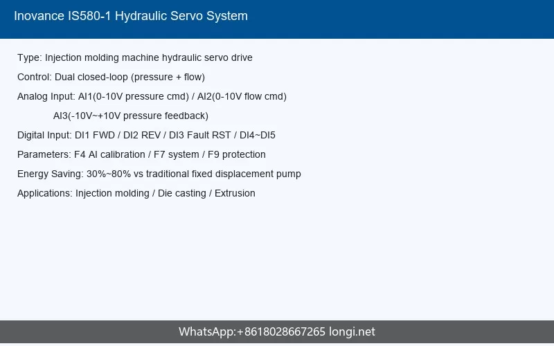
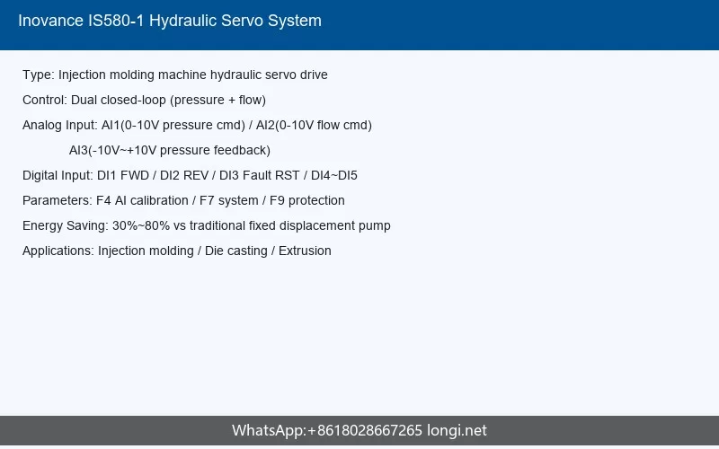
The IS580-1 provides five digital inputs (DI1–DI5) and three analog inputs (AI1–AI3), as illustrated in the system connection diagram (Figure 2-1). These terminals form the external command interface:
| Terminal | Default Function | Signal Type | Application in Injection Molding |
|---|---|---|---|
| DI1 | Oil pump enable (F4-00 = 1) | Digital, 24V logic | Master run command from injection machine controller |
| DI2 | No function (F4-01 = 0) | Digital, 24V logic | Configurable for PID selection, CAN enable, or slave addressing |
| DI3 | Fault reset (F4-02 = 9) | Digital, 24V logic | Remote fault clear signal |
| DI4 | No function (F4-03 = 0) | Digital, 24V logic | Configurable for pressure-to-speed mode switch, etc. |
| DI5 | No function (F4-04 = 0) | Digital, 24V logic | Configurable for slave pump address selection |
| AI1 | Oil pressure command | Analog 0–10V | Pressure setpoint from injection machine controller |
| AI2 | Flow command | Analog 0–10V | Flow/speed setpoint from injection machine controller |
| AI3 | Pressure sensor feedback | Analog -10V to +10V | Actual hydraulic loop pressure from pressure transducer |
2.3 Parameter Configuration for External Analog Command
Since the IS580-1 accepts analog voltage commands rather than pulse trains, servo engineers must configure the analog input scaling parameters to achieve precise “position-equivalent” control — i.e., mapping the injection machine controller’s voltage output to exact hydraulic cylinder movement profiles:
- F4-18 / F4-20 (AI1 Min/Max Input): Defines the voltage range for AI1. Default: 0.02V minimum, 10.00V maximum. Corresponding percentage scaling is set by F4-19 and F4-21 (default 0.0% to 100.0%).
- F4-23 / F4-25 (AI2 Min/Max Input): Defines the voltage range for AI2. Default: 0.02V minimum, 10.00V maximum.
- F4-28 / F4-30 (AI3 Min/Max Input): Defines the voltage range for AI3. Default: 0.02V minimum, 10.00V maximum. Note: AI3 is factory-configured for pressure sensor feedback and supports bipolar -10V to +10V input.
- F4-22 / F4-27 / F4-32 (Input Filter Time): Sets the first-order filter time constant for AI1, AI2, and AI3 respectively. Default values: AI1=0.010s, AI2=0.005s, AI3=0.000s. Increasing these values reduces command ripple but adds response delay.
2.4 Fixed-Length Positioning Equivalent: Injection Cycle Control
In a standard servo positioning system, “fixed-length positioning” refers to moving a load by a precise linear or angular displacement. In the IS580-1 hydraulic servo system, the equivalent function is achieved through the injection molding machine’s sequential control of pressure and flow phases. The drive executes the following profile:
- Injection Phase: The injection machine controller sends a high flow command (AI2 = high voltage) and moderate pressure command (AI1 = proportional to mold resistance). The servo motor accelerates the hydraulic pump to deliver high flow rate.
- Packing/Holding Pressure Phase: When the mold is nearly full, the controller switches to pressure-dominant control via DI terminal function 52 (Pressure-to-Speed Mode Switch) or through PID selection terminals (DI functions 48/49). The drive transitions to closed-loop pressure regulation using AI3 feedback.
- Cooling Phase: The drive maintains holding pressure with minimal flow until the gate freezes.
- Release/Return Phase: The controller reverses the flow command direction (via FED/REV) or reduces AI2 to zero.
The “fixed length” in hydraulic terms is the programmed shot size, which is determined by the cumulative flow volume (integral of pump displacement × speed × time). The IS580-1’s F7-06 Load Speed Display Coefficient (range 0.0001–6.5000, default 1.0000, resolution 0.0001) can be used to calibrate the displayed speed so that the injection machine’s controller can compute volumetric displacement accurately.
3. Electronic Gear Ratio Setting and Calculation
3.1 Why the IS580-1 Does Not Use Traditional Electronic Gearing
The electronic gear ratio — expressed as a fraction Numerator / Denominator that scales command pulses to motor encoder counts — is a cornerstone of general-purpose motion control. It allows a controller to send, for example, 10,000 pulses per mechanical revolution while the motor encoder has 131,072 counts per revolution (17-bit). The gear ratio 131072 / 10000 = 13.1072 reconciles these scales.
The IS580-1 series does not implement electronic gear ratio parameters because it is not a pulse-command position servo. Its command interface is voltage-based (0–10V and -10V to +10V analog signals). The scaling between command signal and motor response is governed by analog input calibration and software gain parameters rather than pulse-count multiplication.
3.2 Analog Command Scaling as the Functional Equivalent
Servo engineers can achieve equivalent scaling behavior by carefully configuring the analog input parameters. The following methodology provides the analog-domain “gear ratio” calculation:
Step 1 — Define Full-Scale Command Voltage
The injection machine controller typically outputs 0–10V for both pressure and flow commands. Set F4-20 (AI1 Max Input) = 10.00V and F4-25 (AI2 Max Input) = 10.00V.
Step 2 — Define Corresponding Output Percentage
Set F4-21 (AI1 Max Input Corresponding Setting) = 100.0% and F4-26 (AI2 Max Input Corresponding Setting) = 100.0%. This ensures that 10V corresponds to 100% of the respective command scale.
Step 3 — Apply Linear Offset if Required
If the controller has a non-zero idle voltage (e.g., 0.25V at zero command), set F4-18 (AI1 Min Input) and F4-19 (AI1 Min Corresponding Setting) to establish the correct zero-offset calibration, preventing pump creeping at null command.
Step 4 — Calibrate Speed Display Coefficient
Parameter F7-06 acts as the display-domain scaling factor. If the hydraulic pump has a displacement of D cc/rev and the motor’s rated speed is N_rated rpm, the maximum flow rate is:
Q_max = D × N_rated / 1000 (L/min)
To make the display show actual flow rate instead of motor frequency, set:
F7-06 = (Pump Displacement in cc/rev × 10^-3) × 60 / (Motor Pole Pairs)
This coefficient effectively creates a “gear ratio” between electrical frequency and mechanical hydraulic flow, analogous to how an electronic gear ratio maps pulses to encoder counts.
3.3 Resolver and Encoder Scaling via PG Cards
The IS580-1 supports multiple feedback device types through interchangeable PG cards, which affects the feedback scaling:
| PG Card Type | Part Number | Feedback Device | Scaling Consideration |
|---|---|---|---|
| Built-in PG | Standard | Resolver (R1) or Differential Encoder (D) | Resolver: single-turn absolute within one electrical cycle. Differential encoder: pulse count depends on line count (e.g., 2500 ppr × 4 = 10000 counts/rev). |
| Multi-function PG Card | MD38PGMD | Differential / Open-collector encoder | Supports higher resolution encoders up to several hundred kHz. |
| Resolver PG Card | S58-PG-B1 | Resolver (sine/cosine) | Standard for harsh oil-mist environments. Robust against vibration and temperature. |
For the differential encoder option, the motor speed is calculated as:
Speed (rpm) = (Pulse Frequency × 60) / (Encoder Lines × 4)
This equation is the feedback-side equivalent of an electronic gear ratio: it converts raw encoder pulse frequency into meaningful rotational speed. The drive’s vector control algorithm uses this feedback to close the speed loop, while the outer pressure loop (when active) closes through the AI3 pressure sensor signal.
4. Common Fault Codes and Troubleshooting
Chapter 6 of the manual covers Maintenance, Fault Diagnosis, and Troubleshooting. The IS580-1 implements a comprehensive fault protection system with over 40 distinct fault codes. Parameter group F9 logs fault history (F9-18: First Fault Type, F9-19: Second Fault Type, F9-20: Third/Most Recent Fault Type), while parameters F9-21 through F9-25 record the operational snapshot at the time of fault: frequency, current, DC bus voltage, input terminal states, and output terminal states.
4.1 Current-Related Faults
| Code | Name | Possible Cause | Troubleshooting Action |
|---|---|---|---|
| ERR02 | Overcurrent during Acceleration | Excessive acceleration ramp; low motor inductance; mechanical jam; incorrect motor parameters | Increase acceleration time (F0 group); verify motor parameter auto-tuning (A2-01); check mechanical coupling for seizure; reduce load inertia. |
| ERR03 | Overcurrent during Deceleration | Short deceleration time; excessive regenerative energy; braking resistor failure | Extend deceleration time; verify braking resistor is connected and within resistance/tolerance specification; check braking unit functionality (internal up to 75kW, external MDBUN for 90kW+). |
| ERR04 | Overcurrent at Constant Speed | Sudden load increase; motor stall; encoder signal loss causing vector control failure | Inspect mechanical load for blockage; verify encoder cable shield is grounded at one end only (Section 3.2.4); check PG card connectors. |
| ERR18 | Current Detection Fault | Current sensor (Hall) failure; control board analog circuit fault | Power cycle the drive; if fault persists, replace control board or contact Inovance service. |
| ERR23 | Ground Short Circuit | Motor winding insulation breakdown; cable damage; moisture ingress | Disconnect motor leads and perform 500V megger test (must exceed 5 MΩ, per Section “Motor Insulation Check”); inspect cables for abrasion; dry motor windings. |
| ERR40 | Wave-by-Wave Current Limit | Severe output current spike exceeding hardware protection threshold | Check for intermittent short in motor cables; reduce PWM carrier frequency if set too high; verify proper output reactor/du/dt filter installation when cable exceeds 100m. |
4.2 Voltage-Related Faults
| Code | Name | Possible Cause | Troubleshooting Action |
|---|---|---|---|
| ERR05 | Overvoltage during Acceleration | High mains voltage; power regeneration from fast acceleration of high-inertia load | Verify input voltage is within 380–480VAC ±10%; extend acceleration ramp; install appropriately sized braking resistor. |
| ERR06 | Overvoltage during Deceleration | Excessive regenerative energy during deceleration; braking resistor undersized or disconnected | Install or resize braking resistor per Chapter 7.8; extend deceleration time; enable DC bus overvoltage stall function if available. |
| ERR07 | Overvoltage at Constant Speed | Unstable mains supply; load driving motor (regenerative mode) | Check mains voltage stability; verify load is not back-driving the motor; check braking unit activation threshold (F9-08 default 780V). |
| ERR09 | Undervoltage | Mains voltage sag; phase loss; pre-charge circuit failure; DC bus capacitor degradation | Measure input voltage at R/S/T terminals; verify all three phases present; check input contactor and pre-charge relay; wait 10 minutes after power-down before inspection (residual voltage hazard). |
4.3 Thermal and Overload Faults
| Code | Name | Possible Cause | Troubleshooting Action |
|---|---|---|---|
| ERR10 | Inverter Overload | Exceeding 150% rated current for prolonged period; inadequate drive sizing; high ambient temperature; blocked cooling airflow | Verify drive power rating exceeds motor power; reduce duty cycle; clean heatsink and fan; ensure cabinet inlet temperature remains below 50°C (Section 3.1.1); check installation spacing (A≥50mm for 30kW+ models). |
| ERR14 | Heatsink Overtemperature | Fan failure; clogged heatsink fins; ambient temperature exceeding 50°C; derating not applied for altitude >1000m | Check F7-07 for actual heatsink temperature reading; verify fan rotation; clean heatsink; install cabinet cooling; apply altitude derating (1% per 100m above 1000m) and temperature derating (1.5% per °C above 40°C). |
| ERR45 | Motor Overtemperature | Inadequate motor cooling; excessive continuous torque; KTY/PTC sensor trip | Verify motor cooling fan operation; check motor thermal model parameter F9-16 (default enabled); ensure motor is not operating above its S1 duty rating. |
| ERR61 | Braking Transistor Timeout | Braking unit continuously active beyond safe duty cycle; braking resistor wattage too low | Increase deceleration time to reduce regenerative duty cycle; upgrade to higher-wattage braking resistor; verify F9-08 braking activation voltage setting. |
4.4 Phase and Communication Faults
| Code | Name | Possible Cause | Troubleshooting Action |
|---|---|---|---|
| ERR12 | Input Phase Loss | Blown input fuse; loose terminal screw; upstream contactor fault; grid phase imbalance | Check all three input phases with multimeter; verify input contactor closes properly; tighten R/S/T terminal screws to torque specification (Section 7.5). |
| ERR13 | Output Phase Loss | Broken motor lead; loose U/V/W terminal; failed output reactor; open winding | Measure motor winding continuity; verify U/V/W terminal torque; inspect output reactor/reactor connections; check motor winding resistance balance. |
| ERR16 | Serial Communication Fault | Broken RS485 wiring; incorrect Modbus parameters (FD group); EMI interference; master timeout | Verify FD-00 baudrate (default 9600bps), FD-01 data format (default 8,N,2), FD-02 address (default 1), FD-04 timeout (default 0.0s = disabled); check 485+ and 485- wiring polarity; use twisted-pair shielded cable with shield grounded at drive end. |
| ERR42 | CAN Communication Fault | Multi-pump CAN bus wiring fault; termination resistor missing; slave address conflict | Verify CAN_H and CAN_L continuity; install 120Ω termination resistors at both bus ends; ensure unique CAN addresses for each slave pump; check DI5/DI4 slave address selection terminals (functions 53/54). |
| ERR48 | CAN Address Conflict | Two or more pumps configured with identical CAN node ID | Reconfigure slave address selection terminals (DI functions 53/54) so each pump has a unique address in the multi-pump system. |
4.5 Mechanical and Tuning Faults
| Code | Name | Possible Cause | Troubleshooting Action |
|---|---|---|---|
| ERR17 | Contactor Fault | Pre-charge contactor (buffer relay) failed to close or weld closed; auxiliary contact feedback error | Measure contactor coil voltage; inspect contactor mechanical condition; verify contactor auxiliary contact wiring to control board. |
| ERR19 | Motor Auto-Tuning Fault | Excessive load during stationary tuning; motor not connected; incorrect motor rated parameters; encoder not connected | Disconnect mechanical load (pump coupling) before tuning; verify motor rated current, voltage, frequency, and pole number parameters; ensure encoder cable is properly seated on PG card. |
| ERR43 | Resolver Tuning Fault | Resolver excitation or feedback signal error; resolver ratio mismatch | Check resolver wiring (S58-PG-B1 card); verify resolver pole ratio matches motor pole pairs; inspect resolver for mechanical damage. |
| ERR44 | Speed Deviation Protection | Excessive difference between command speed and actual speed; mechanical slip; encoder resolution error | Check coupling between motor and pump for slippage; verify encoder line count; increase F9-14 speed deviation threshold (default 10.00Hz) or F9-15 judgment time (default 10.0s) if mechanical system has inherently high compliance. |
| ERR49 | Resolver PG Disconnection | Resolver cable open or short; connector loose; resolver winding failure | Inspect resolver cable continuity; measure resolver winding resistance; reseat PG card connector. |
4.6 Application-Specific Faults
| Code | Name | Possible Cause | Troubleshooting Action |
|---|---|---|---|
| ERR46 | Oil Pump Sensor Fault | Pressure sensor disconnected; AI3 signal out of range; sensor power supply (+13V) failure | Verify pressure sensor connected to AI3; check +13V sensor power output; verify sensor output is within -10V to +10V range; inspect sensor diaphragm for clogging. |
| ERR47 | Slave Pump Pre-Alarm | Secondary pump in multi-pump system reporting abnormal condition before fault trip | Check CAN communication to slave; inspect slave pump motor temperature and current; verify slave drive fault history. |
| ERR52 | Multi-Pump Flow-Merge Multi-Master Fault | Two or more pumps configured as master in a parallel flow-merge system | Ensure only one pump has DI function 51 (Slave-as-Master Enable) active; verify master/slave configuration per Appendix C (Sections C.3–C.5). |
| ERR59 | Back-EMF Abnormality | Encoder direction reversed relative to U/V/W phase sequence; incorrect motor wiring; demagnetized motor | Swap any two motor power leads (U/V/W) to correct rotation; verify encoder count direction matches motor rotation; test motor back-EMF with oscilloscope—sinusoidal waveform should be balanced and amplitude proportional to speed. |
4.7 General Troubleshooting Workflow
When a fault occurs, follow this systematic diagnostic procedure:
- Record the fault code displayed on the LED panel. Cross-reference with F9-18 (First Fault Type) to confirm the primary fault, as secondary faults may cascade.
- Capture the operational snapshot from F9-21 (Fault Frequency), F9-22 (Fault Current), F9-23 (Fault Bus Voltage), F9-24 (Input Terminal States), and F9-25 (Output Terminal States) to reconstruct the pre-fault operating point.
- Remove power and wait a minimum of 10 minutes before opening the enclosure, as the DC bus capacitors retain lethal voltage (Section 5, Safety Information).
- Address the root cause per the tables above. Never attempt to reset a fault (RES key or DI3 fault reset) without first eliminating the underlying cause.
- Power on and test at reduced load. Monitor F7-07 (Heatsink Temperature) and F7-09 (Accumulated Runtime) to verify healthy thermal and operational margins.
5. Conclusion
The Inovance IS580-1 series servo drive represents a specialized evolution of servo technology tailored for the demanding hydraulic environments of injection molding machines. Unlike general-purpose servo positioners that rely on pulse-train command interfaces and electronic gear ratios, the IS580-1 implements an analog-command hydraulic control paradigm: 0–10V pressure and flow commands, closed-loop pressure feedback via AI3 (-10V to +10V), and high-performance vector control of permanent magnet synchronous motors with resolver or differential encoder feedback.
The operation panel provides a comprehensive local interface with RUN/STOP/RESET control, three-level menu parameter access, multi-tier password protection, and LED status indicators for RPM, percentage, amperes, volts, and hertz. While traditional “position mode with pulse input” and “electronic gear ratio” concepts do not directly apply to this hydraulic servo architecture, engineers can achieve equivalent system calibration through careful analog input scaling (F4-18 through F4-32) and the load speed display coefficient (F7-06), effectively creating a scaling relationship between command voltage and hydraulic flow output.
The drive’s fault protection system is extensive, covering over 40 distinct fault conditions from simple overcurrent and overvoltage events to injection-application-specific faults such as oil pump sensor errors (ERR46), multi-pump CAN conflicts (ERR48/ERR52), and resolver disconnection (ERR49). The hierarchical fault logging (three-event history) and automatic operational data capture at trip time provide servo engineers with powerful diagnostic tools for rapid troubleshooting and root-cause analysis.
For successful deployment, engineers must respect the IS580-1’s design boundaries: it is an oil-pump servo system, not a general CNC positioning servo. Proper application requires correct motor-to-pump mechanical coupling, accurate pressure sensor calibration, appropriate braking resistor sizing (internal up to 75kW, external MDBUN for 90kW and above), strict adherence to EMC shielding and grounding requirements, and thermal management that keeps inlet air temperature below 50°C with adequate installation clearances. When these guidelines are followed, the IS580-1 delivers the enhanced pressure and speed response, reduced steady-state pressure fluctuation, and compact footprint that differentiate it from both its IS300 predecessor and conventional induction-motor hydraulic systems.
Document reference: Inovance IS580-1 Series Servo Drive User Manual, Document Code 19010279, Version B04. All technical parameters and fault codes are extracted directly from the official manual. For the latest firmware and documentation updates, visit www.inovance.com.