
Inovance MD290 Series Inverter User Guide: Operation Panel, Terminal Control, Parameter Setting and Fault Troubleshooting
1. Introduction and Overview
The Inovance MD290 series is a general-purpose variable frequency drive (VFD) designed primarily for controlling and regulating the speed and torque of three-phase AC induction motors. With robust functionality, stable performance, and flexible configurability, the MD290 is suitable for a broad spectrum of industrial automation applications including textile machinery, paper processing, wire drawing, machine tools, packaging equipment, food processing, fans, pumps, and various automated production lines.
The product family encompasses thirteen chassis sizes (T1 through T13), covering motor power ratings from 0.4 kW to 800 kW. The series supports three voltage classes: three-phase 380 V to 480 V, three-phase 200 V to 240 V, and single-phase 200 V to 240 V. Model designation follows the format MD290T[Power]G/[Power]P[B], where “G” denotes constant-torque (heavy-duty) rating, “P” denotes variable-torque (light-duty) rating, and the optional suffix “B” indicates built-in braking unit. Additional suffixes include -T for models with DC reactor and -L for models with AC output reactor.
Key product features include user-programmable logic capability, PC-based software monitoring, multi-protocol communication bus support (RS485, CAN, EtherCAT, Profinet), and comprehensive protection functions. The MD290 provides V/F control mode as standard, with advanced features such as PID control, simple PLC sequencing, multi-step speed operation, jog operation, master-slave control, and instantaneous power-loss ride-through capability. The drive also supports motor autotuning (parameter identification) for optimizing control performance.
This guide focuses on practical operational aspects: LED keypad usage, terminal wiring configuration, parameter management, and systematic fault diagnosis procedures based on the MD290 technical manual (Publication B01, September 2022).
2. LED Operation Panel Usage
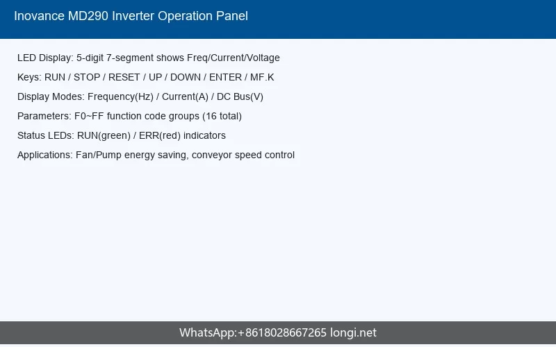
2.1 Panel Layout and Display Modes
The MD290 features a standard LED operation panel (operation keypad) for local monitoring and parameter configuration. The panel displays operational status, parameter values, and fault information through a digital LED display. The standard panel is identified as the built-in LED keypad, with optional external keypads available including the MD32NKE1 LED keypad and the MDKE9 LCD keypad for enhanced display capabilities.
The LED panel supports multiple display modes for comprehensive system monitoring. The primary status parameter display shows real-time operating data including:
- Running frequency (U0-00, address 0x7000, resolution 0.01 Hz)
- Set frequency (U0-01, address 0x7001, resolution 0.01 Hz)
- DC bus voltage (U0-02, address 0x7002, resolution 0.1 V)
- Output voltage (U0-03, address 0x7003, resolution 1 V)
- Output current (U0-04, address 0x7004, resolution 0.01 A)
- Output power (U0-05, address 0x7005, resolution 0.1 kW)
- Output torque (U0-06, address 0x7006, resolution 0.1%)
Additional monitor parameters include DI input status (U0-07), DO output status (U0-08), analog input voltages AI1/AI2/AI3 (U0-09 through U0-11), pulse input frequency (U0-18), PID setpoint and feedback (U0-15, U0-16), motor temperature (U0-34), and accumulated power consumption (U0-76, U0-77). The monitor parameter group (U0 group) provides a comprehensive window into drive and system status during operation and commissioning.
2.2 Key Functions and Navigation
The LED operation panel provides several functional keys for navigation and control. The fundamental operations include:
- Parameter browsing: Users can navigate through parameter groups (F0, F1, F2, etc., plus A1-A8 auxiliary groups, U0 monitor group, AC calibration group) to locate specific function codes for viewing or modification.
- Parameter setting: After locating a parameter, press the programming key to enter edit mode. Use the increment/decrement keys to adjust the value, then confirm to save. Parameters may require a STOP condition for modification depending on their change permission attribute.
- Status display toggle: The panel can cycle through different monitor items during operation, allowing operators to observe critical process variables in real time.
- Quick menu access: Frequently accessed parameters can be organized into user-defined custom parameter groups for rapid configuration.
2.3 MF.K Multi-Function Key Operation
The MF.K key on the operation panel serves as a user-configurable multi-function button. Its behavior is programmable through the parameter system, enabling operators to assign commonly used functions for one-touch access. Typical assignments include jog operation activation, quick parameter recall, or emergency stop functions. This configurable key enhances operational efficiency by reducing navigation steps for repetitive tasks during commissioning and daily operation.
2.4 Panel-Related Parameters
Several parameters govern the operation panel behavior:
| Parameter | Function | Default |
|---|---|---|
| F0-01 | Run command channel selection (0: panel, 1: terminal, 2: communication) | 0 |
| F0-02 | Main frequency source selection (0: panel, 1: AI1, 2: AI2, etc.) | 0 |
| F7-01 | User password setting | 0 |
| F7-02 | Parameter initialization selection | 0 |
3. Terminal Control and Wiring
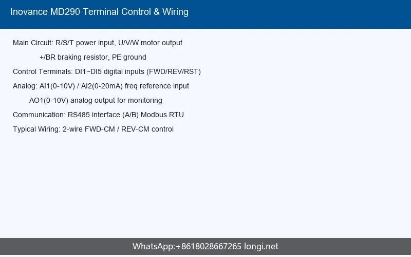
3.1 Main Circuit Terminals
The main power circuit terminals provide the fundamental power path for the MD290. Standard terminal designations are:
- R, S, T: Three-phase AC power input terminals. For single-phase models, connect to R and T terminals.
- U, V, W: Three-phase AC output terminals connecting to the motor.
- PE: Protective earth (ground) terminal – critical for safety and EMI compliance.
- + , -: DC bus terminals (available on certain models) for external braking unit or DC bus connection.
- P, N: Internal DC bus connection points.
Main circuit wiring requirements specify that input power must never be connected to the output terminals (U, V, W), as this will cause severe drive damage and potential fire hazard. Motor phase sequence must match the drive output phase sequence to prevent reverse rotation. The manual emphasizes that terminal screws must be tightened to the specified torque values; insufficient torque causes overheating at connections, while excessive torque may damage terminals.
Chassis sizes T1 through T6 utilize plastic enclosures, while T7 through T13 employ metal sheet construction. The main circuit terminal sizes and recommended cable gauges vary by chassis size and current rating. For example, T1 models (up to 3.7 kW) use smaller terminal blocks compared to T13 models (500-800 kW) which require heavy-duty busbar connections.
3.2 Control Circuit Terminals
The control terminal section provides the interface for external control signals, analog I/O, and communication. Standard control terminals include:
| Terminal | Type | Function |
|---|---|---|
| DI1-DI5 | Digital Input | Programmable digital inputs (FWD, REV, reset, multi-speed, etc.) |
| DI5/FM | Dual-function | Digital input DI5 or high-speed pulse input/output (FM) |
| AI1 | Analog Input | 0-10V or 0-20mA input for frequency reference |
| AI2 | Analog Input | 0-10V or 0-20mA input for auxiliary reference |
| AI3 | Analog Input | Voltage/current/PTC input (configurable via A7-02) |
| AO1 | Analog Output | 0-10V output for frequency/current monitoring |
| AO2 | Analog Output | Voltage/current output configurable via A7-02 |
| DO1 | Digital Output | Open-collector programmable output |
| FMR | Relay Output | Relay contact output (T/A-T/B-T/C) |
| 485+ / 485- | Communication | RS485 Modbus RTU interface |
| CAN | Communication | CAN bus interface (optional with expansion cards) |
3.3 Typical Control Wiring Configuration
A standard two-wire control configuration for basic start/stop operation uses:
- Connect a maintained contact (start button or switch) between +24V and DI1 (Forward Run).
- Connect a second maintained contact between +24V and DI2 (Reverse Run), if bidirectional operation is required.
- Connect a normally-closed contact between +24V and DI3 (External Fault Input) for safety interlock.
- Connect a normally-open momentary contact to DI4 for fault reset.
- Program DI1-DI4 functions through parameters F4-00 through F4-04 to assign Run Forward, Run Reverse, External Fault, and Fault Reset functions respectively.
- Connect analog speed reference (0-10V potentiometer or PLC output) between AI1 and GND.
- Connect relay output terminals to external indicators or PLC inputs for Run Status and Fault Status feedback.
3.4 Communication Wiring
The MD290 supports multiple industrial communication protocols through built-in and expansion card options:
- RS485 (Modbus RTU): Built-in interface supporting baud rates up to 115200 bps. Standard two-wire half-duplex connection to 485+ and 485- terminals. Supports master-slave architecture with address configuration through FD group parameters.
- CAN/CANopen: Available through communication expansion cards for distributed control applications.
- Profibus-DP: Supported via MD-SI-DP1 expansion card.
- Profinet: Supported via MD500-PN2 expansion card for Ethernet-based industrial networks.
- EtherCAT: Supported via dedicated expansion card for high-performance synchronized motion control.
4. Parameter Initialization and Password Management
4.1 Parameter Structure
The MD290 organizes parameters into functional groups for systematic configuration:
- F0 group: Basic function parameters (control mode, frequency source, run command source, acceleration/deceleration times)
- F1 group: Motor parameters and V/F curve settings
- F2 group: Start/stop control and braking parameters
- F3 group: Multi-speed and simple PLC parameters
- F4 group: Digital and analog I/O terminal configuration
- F5 group: Keyboard and display parameters
- F6 group: Communication parameters
- F7 group: User settings including password and initialization
- F8 group: Auxiliary function parameters
- F9 group: PID control parameters
- FA group: Swing frequency and fixed-length control
- FB group: Protection parameters
- FC group: Second motor parameters
- A1 group: Virtual digital I/O configuration
- A2 group: Advanced motor parameters for autotuning
- A5-A7 groups: Advanced control and programmable card functions
- U0 group: Monitor parameters (read-only)
- AC group: Analog calibration parameters
4.2 Password Management
The MD290 incorporates a user password protection system to prevent unauthorized parameter modification. When a password is set (F7-01, default 0 meaning no password), the drive requires password entry before allowing parameter changes. This feature is essential in industrial environments where process settings must remain locked after commissioning.
To set a password:
- Navigate to parameter F7-01 (User Password).
- Enter a non-zero value (typically 1-65535) as the password.
- Press ENTER to save. The password takes effect immediately.
Once a password is active, any attempt to modify parameters will prompt for the password. The password must be entered correctly to unlock parameter write access. Setting F7-01 back to 0 removes password protection, but this requires first entering the existing password.
For additional security, the drive supports parameter hiding through the user custom parameter function (F7-02/F7-03), which allows creating a restricted parameter list showing only relevant parameters for daily operation while hiding advanced or sensitive configuration items.
4.3 Parameter Initialization
Parameter initialization (factory reset) is available when returning the drive to default settings or recovering from incorrect configurations. The initialization function is accessed through parameter F7-02:
| F7-02 Value | Action |
|---|---|
| 0 | No action (default) |
| 1 | Restore all parameters to factory defaults (excluding motor parameters) |
| 2 | Clear fault history record |
| 3 | Restore all parameters including motor parameters to factory defaults |
| 4 | Back up current parameters to internal memory |
| 5 | Restore parameters from internal backup memory |
4.4 Data Backup and Recovery
The MD290 provides parameter backup functionality to internal non-volatile memory. Users can save a complete parameter set to backup memory (F7-02 = 4) and later restore it (F7-02 = 5). This capability is valuable for:
- Creating known-good configuration checkpoints during commissioning
- Rapidly duplicating settings across multiple drives in the same application
- Recovering from experimental parameter changes without manual re-entry
For large-scale deployments, the Inovance commissioning software enables batch parameter upload/download via the RS485 communication interface, significantly reducing configuration time for multi-drive installations.
5. Common Fault Codes and Troubleshooting
5.1 Fault Display and Classification
When the MD290 detects an abnormal condition, it displays a fault code on the LED panel in the format ERR-XX where XX represents the fault number. The drive enters a protective shutdown state, the output is disabled, and the motor coasts to a stop (unless DC braking is configured). The most recent fault code is stored in parameter U0-62 (Current Fault, address 0x703E), and the fault history log retains previous occurrences for diagnostic review.
Faults are classified by severity and response type:
- Free-stop faults: Drive immediately disables output; motor coasts to stop. These include overcurrent, overvoltage, module faults, and overtemperature conditions.
- Deceleration-stop faults: Drive follows programmed deceleration ramp before stopping. Typically used for less critical conditions.
- Continue-operation alarms: Drive displays warning but maintains operation. Examples include overload pre-warning and parameter verification warnings.
5.2 Fault Restart Behavior
The automatic restart function (parameter FB group) can be configured to attempt recovery after certain faults. When enabled, the drive automatically resets the fault and restarts operation after a programmable delay. This function is useful for applications with transient disturbances (momentary power dips, brief overloads), but should be used with caution in machinery where unexpected restart poses safety risks. Parameter FB-00 controls the restart mode:
- 0: No automatic restart
- 1: Restart after fault reset with speed tracking
- 2: Restart after power recovery
The speed tracking function allows the drive to catch a spinning motor upon restart without requiring a full stop, minimizing process disruption in fan and pump applications.
5.3 Common Fault Codes
Based on the MD290 fault code table, the following represent the most frequently encountered faults in field operation:
| Fault Code | Fault Name | Probable Causes | Recommended Actions |
|---|---|---|---|
| ERR-01 | IGBT Module Protection (Overcurrent) | Short circuit at output; motor insulation failure; excessive load torque; acceleration time too short; IGBT damage | Check motor wiring for shorts; measure motor insulation resistance (>5 MΩ); increase acceleration time (F0-17); verify load is not mechanically jammed; replace drive if IGBT failure confirmed |
| ERR-02 | Overcurrent During Acceleration | Acceleration time too short; load inertia too large; V/F curve inappropriate; motor parameters incorrect | Extend acceleration time; enable S-curve acceleration; increase torque boost (F1-05); perform motor autotuning (A2-37); verify motor nameplate data matches F1 group parameters |
| ERR-03 | Overcurrent During Deceleration | Deceleration time too short; excessive regenerative energy; braking resistor undersized or disconnected | Extend deceleration time; install or verify braking resistor connection; enable overvoltage stall function (F3-08); consider external braking unit for high-inertia loads |
| ERR-04 | Constant Speed Overcurrent | Sudden load increase; mechanical binding; motor phase loss during operation | Inspect mechanical system; check motor current balance; verify drive output current rating matches application requirements |
| ERR-05 | Overvoltage | Excessive regenerative energy; deceleration too rapid; incoming line voltage too high | Verify input voltage within specification (< 480V AC for 380V class); extend deceleration time; install braking resistor; enable overvoltage stall function |
| ERR-06 | Undervoltage | Input voltage too low; momentary power loss; input phase loss; pre-charge failure | Measure input voltage; verify all three phases present; check input fuses and contactor; verify voltage drop during startup does not exceed 15% |
| ERR-07 | Module Overtemperature | Ambient temperature too high; cooling fan failure; blocked air intake; excessive switching frequency; prolonged overload operation | Verify ambient temperature < 40°C (or derated 40-50°C); check cooling fan operation; clean air filter/dust; reduce carrier frequency (F0-15); verify drive is adequately sized for load |
| ERR-08 | Inverter Overload | Drive rated current insufficient for application; prolonged operation above 150% rated current | Verify drive sizing against load profile; reduce load or upsize drive; check for mechanical overload conditions; review acceleration/deceleration profiles |
| ERR-09 | Motor Overload | Motor thermal model indicates excessive heating; mechanical overload; inadequate motor cooling | Verify motor thermal current setting (F1-01) matches motor rated current; reduce load; check motor cooling fan; adjust motor overload protection curve (FB group) |
| ERR-10 | Input Phase Loss | Missing input phase; loose terminal connection; input fuse blown; contactor fault | Check all three input phases with multimeter; tighten input terminals; replace fuses; verify contactor pulls in completely; disable phase loss detection (FB-13) only as temporary measure |
| ERR-11 | Output Phase Loss | Disconnected motor lead; open motor winding; severe current imbalance | Check motor connections at drive and motor terminals; measure motor winding resistance (should be balanced within 5%); inspect for broken wires or loose terminals |
| ERR-14 | External Fault | External emergency stop activated; safety interlock opened; auxiliary equipment fault | Check external fault input (DI terminal configured as external fault); verify safety circuits; inspect interlocked auxiliary equipment status |
| ERR-16 | Communication Fault | Communication cable disconnected; interference; master station stopped; incorrect baud rate or address | Verify RS485 cable continuity; check shield grounding; verify communication parameters (F6 group) match master station; inspect for electromagnetic interference sources |
| ERR-17 | Current Detection Fault | Current sensor fault; control board hardware issue | Power cycle drive; if fault persists, contact Inovance service for control board replacement |
| ERR-18 | Motor Autotuning Fault | Autotuning aborted; motor not connected; excessive load during tuning | Disconnect motor from mechanical load for tuning; verify motor wiring; ensure motor is at standstill before starting autotuning; repeat autotuning procedure |
| ERR-23 | EEPROM Fault | Parameter storage memory corruption; control board issue | Perform parameter initialization (F7-02 = 1 or 3); reconfigure all parameters; if fault recurs, replace control board |
| ERR-24 | Factory Data Fault | Factory calibration data corrupted | Contact Inovance service – requires factory recalibration or control board replacement |
5.4 V/F Control Mode Commissioning Faults
During initial commissioning in V/F control mode, specific symptoms may indicate parameter misconfiguration:
- Motor does not rotate, no output current: Check run command source (F0-01) and frequency reference source (F0-02). Verify parameter lock status (password). Confirm external enable/interlock circuits.
- Motor rotates but abnormal noiseheat: Verify V/F curve setting matches motor nameplate frequency (F1-04/F1-05). Check torque boost is not excessive (F1-06). Confirm motor rated current (F1-01) and rated frequency (F1-04) are correctly entered.
- Motor stalls at low speed: Increase torque boost gradually (default 0.0%, typically set 2-5% for general loads, up to 10% for high-torque applications). Enable automatic torque boost (auto-torque compensation) if available for the load type.
- Excessive vibration: Adjust carrier frequency (F0-15) to higher setting (up to 8 kHz for quiet operation, though thermal derating may be required). Enable skip frequency bands (F8-09 through F8-14) to avoid mechanical resonance frequencies.
- DC bus overvoltage during deceleration: Enable overvoltage stall function (F3-08 = 1). Extend deceleration time (F0-18). Verify braking resistor is properly connected and sized for the application’s regenerative energy.
5.5 Diagnostic Tools and Monitor Parameters
The U0 group monitor parameters serve as powerful diagnostic tools during troubleshooting:
- U0-02 (Bus Voltage): Verify DC bus voltage is approximately 1.35 × AC input voltage (e.g., 540V for 400V AC input). Values significantly higher indicate regenerative overvoltage; lower values indicate undervoltage or phase loss.
- U0-04 (Output Current): Compare against motor rated current. Sustained values above 100% indicate potential overload or undersized application.
- U0-07 (DI Input Status): Bit-mapped display showing which digital inputs are active. Use to verify control signals are reaching the drive.
- U0-09 through U0-11 (AI1/AI2/AI3): Verify analog reference signals are present and within expected range (0-10V or 4-20mA).
- U0-34 (Motor Temperature): If motor thermistor (PTC/PT100) is connected to AI3, monitor motor thermal state directly.
6. Conclusion
The Inovance MD290 series general-purpose inverter delivers a comprehensive and flexible motor control solution for industrial automation applications ranging from 0.4 kW to 800 kW. Its well-structured parameter organization, versatile control interfaces, and extensive protection features make it suitable for both simple standalone applications and complex integrated control systems.
Successful commissioning and long-term reliable operation depend on careful attention to installation requirements, proper terminal wiring with adequate shielding, accurate motor parameter configuration, and systematic fault diagnosis when issues occur. The LED operation panel provides intuitive local access to all drive functions, while the extensive monitor parameter set (U0 group) offers real-time visibility into system behavior during both normal operation and fault conditions.
Technicians working with the MD290 should maintain detailed commissioning records including motor parameter entries, V/F curve settings, terminal function assignments, and any customized parameter values. These records accelerate troubleshooting and simplify drive replacement procedures. For applications involving critical processes or safety interlocks, always verify parameter integrity after any initialization or backup restoration operation.
The MD290’s support for multiple communication protocols (Modbus RTU, CANopen, Profibus-DP, Profinet, EtherCAT) through expansion cards ensures compatibility with modern industrial control architectures. When properly configured and maintained according to the guidelines presented in this manual and the complete MD290 technical documentation, this drive series provides years of reliable service across diverse industrial environments.
Document Reference: Based on Inovance MD290 Series General-Purpose Inverter Technical Manual, Publication Version B01 (September 2022), 461 pages.