
GSK GR-L Bus-Type AC Servo Drive Manual Guide: GSK-Link Setup, CN2/CN3 Feedback, PA Parameters, Electronic Gear Ratio, Servo Tuning and AL Alarm Diagnosis
GR-L Is a CNC Bus Servo Axis System
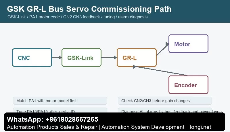
GSK GR-L is not just a pulse servo drive with fewer wires. It is a bus-type AC servo drive unit for CNC machine tools. The important manual topics are GSK-Link, real-time CNC communication, CN2/CN3 feedback, PA parameters, inertia identification, resonance suppression, position control, speed control and torque control.
During commissioning, do not only check whether the drive powers on or whether the motor jogs. A stable axis depends on the CNC, GSK-Link network, drive unit, motor, encoder, mechanical load and PLC diagnosis working as one closed-loop system. Fewer bus wires do not mean easier commissioning; many checks move into the CNC diagnosis screen and parameter system.
Model, Capacity and Feedback Interface
Before replacing a GR-L drive, confirm voltage class, capacity, communication interface, encoder protocol and feedback interface quantity. The manual describes CN2 and CN3 feedback interfaces and support for absolute encoders, incremental encoders, Tamagawa, BISS and EnDat2.2 protocols. Some versions use only CN2 motor feedback, while others also provide CN3 second-position feedback.
A wrong feedback interface can allow the drive to power on but still cause encoder alarms, position feedback errors, orientation failure or a bus axis that cannot be enabled. For spindle or electric-spindle applications, also confirm encoder tooth count and related feedback parameters such as PA200 where applicable.
Power Circuit, Brake and Grounding
GR-L is still a servo power unit. Input power, motor output, brake resistor, PE grounding, shielding, reactors and filters must be checked before tuning. Bus communication does not remove electrical noise. In fact, bus communication, encoder feedback and PWM motor output exist together, so wiring quality is critical.
Keep motor power cable, encoder cable and GSK-Link communication cable separated. Check brake resistor value and power rating, especially on heavy axes and spindles with frequent deceleration. Do not try to solve a wiring, grounding or braking problem by reducing servo gains.
GSK-Link Online Check
Commission the bus in three steps: confirm physical bus wiring, confirm that CNC recognizes the axis, and confirm that drive status matches CNC diagnosis. If the CNC cannot identify the servo axis, electronic gear ratio and gain tuning are meaningless.
Check station number, axis number, cable direction, termination, CNC parameters and drive state. On multi-axis machines, bring axes online one by one. This avoids mixing duplicated station numbers, cable breaks, wrong axis parameters and mechanical problems.
Panel Operation and PA Parameters
The GR-L panel is used for status display, parameter viewing, parameter editing, alarm reset and commissioning. The first key parameter is PA1, the motor model code. The manual requires selecting the motor model code and loading default motor parameters. If PA1 is wrong, current loop, speed loop, encoder setup, rated current and protection thresholds can all be wrong.
After changing important parameters, execute the required save/write operation and verify after power cycling. Record at least PA1, feedback type, second feedback configuration, electronic gear ratio, speed loop, position loop, braking, limit, alarm output and bus-axis parameters.
CN2 and CN3 Feedback
CN2 is normally motor feedback. CN3 can be used for second-position feedback such as linear scale, second spindle encoder or mechanical-end feedback. Feedback faults should be diagnosed in three layers: electrical layer, protocol layer and mechanical layer.
The electrical layer includes connector, shield, supply, cable and pin definition. The protocol layer includes encoder type, communication protocol, resolution and PA parameter match. The mechanical layer includes encoder mounting, coupling slip, scale contamination and backlash. If feedback is unreliable, gain tuning only hides the real problem.
Electronic Gear Ratio
Electronic gear ratio maps CNC command units to motor rotation, screw pitch, reduction ratio or table movement. It is not merely a speed amplifier. It directly affects command resolution, positioning accuracy, following error and machining size.
Before setting the ratio, list CNC command unit, encoder resolution, screw pitch or rotary-axis angle, gear ratio and whether second feedback is used. Start with very small low-speed motion, confirm direction, then test 1 mm, 10 mm and reverse repeatability. Proportional size error usually points to electronic gear or mechanical ratio; large bidirectional error points to backlash or feedback problems.
Inertia Identification and Servo Gain Tuning
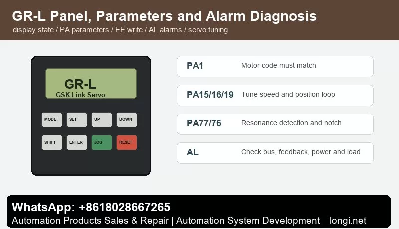
The manual separates basic performance tuning, inertia identification, speed loop, position loop and resonance suppression. The practical sequence is: confirm motor and feedback, perform inertia identification, tune speed loop, then tune position loop.
Parameters such as PA15, PA16, PA18, PA19 and PA23 relate to speed-loop and position-loop behavior. Speed gain too low causes slow response and large contour error; too high causes noise, vibration or overshoot. Position gain too low causes following error; too high causes oscillation if the machine lacks stiffness.
For multi-axis interpolation, keep dynamic response consistent between axes. The manual notes that PA19 should be handled consistently or conservatively after tuning multiple axes. Before inertia identification, ensure there is no active alarm or warning such as AL-603 and that travel is safe.
Resonance Suppression
Machine-axis screaming, vibration or surface marks at certain speed ranges can be mechanical resonance. The manual mentions real-time resonance detection and parameters such as PA77 and PA76. The idea is to detect the resonance frequency, write it into notch parameters, and adjust notch width and depth carefully.
Do not treat every vibration as resonance. Loose encoder coupling, poor bearings, dry guideways, wrong feedback direction or excessive gain can also cause vibration. Real-time detection is a commissioning tool; after identifying the frequency, save the correct notch setting and return the drive to a stable run configuration.
AL Alarm Diagnosis
Communication alarms: check GSK-Link cable, station number, axis number, termination, CNC parameters, power-on sequence and emergency stop state.
Feedback alarms: check CN2/CN3 connectors, encoder supply, shielding, protocol type, PA parameters and mechanical mounting.
Overcurrent, overload or overvoltage: check motor cable, brake resistor, mechanical jam, acceleration/deceleration time, load inertia and motor capacity.
Following error or position abnormality: check electronic gear ratio, position gain, limit signals, backlash, second-feedback direction and CNC axis parameters. Do not simply enlarge the following-error window.
Tuning warnings: clear alarms and interlocks first, confirm safe travel, then run inertia identification or resonance detection.
Commissioning Records
Before delivery, keep records of drive model, motor model, encoder type, CN2/CN3 usage, PA1, electronic gear ratio, loop gains, resonance parameters, brake settings, GSK-Link station/axis number, CNC axis parameters, PLC interlocks and alarm history.
Final testing should include jog, rapid move, homing, reverse repeatability, emergency stop, limit, servo alarm, power-cycle retention, continuous temperature rise and trial cutting. A stable GR-L servo system is not just a motor that rotates; it is an axis that the CNC can identify, the bus can maintain, feedback can prove, parameters can be traced and alarms can be diagnosed.