
1. Overview of the Fault Symptom
The Schneider Electric ATV310 variable frequency drive is widely used in small and medium-power industrial applications, including fans, pumps, conveyors, woodworking machines, packaging equipment, and general three-phase asynchronous motor control. Because the ATV310 is a compact and economical drive, many technicians assume that its fault codes are limited to common electrical problems such as overcurrent, overvoltage, undervoltage, motor overload, overheating, or output phase loss.
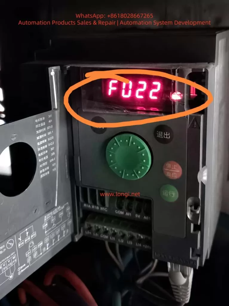
However, in real field service and repair work, one fault is frequently misunderstood: the drive runs normally at a constant speed, then suddenly stops and displays F022. The customer may describe the situation as follows:
The motor runs normally for some time.
The speed is stable, with no acceleration or deceleration at the moment of failure.
The drive suddenly stops.
The display shows F022.
Sending the run command again does not restart the drive.
Only powering off and restarting the drive makes it work again.
After running for a while, the same fault appears again.
This fault is often misdiagnosed as a control board failure, CPU crash, power supply problem, IGBT module fault, motor insulation issue, or internal overheating. In fact, according to the ATV310 fault definition, F022 is not a power-stage fault. It is related to Modbus communication monitoring.
Understanding the real meaning of F022 is the key to solving this problem correctly.
2. What F022 Really Means: Modbus Communication Interruption
On the ATV310, F022 means Modbus interruption. The possible cause is an interruption of communication on the Modbus network.
Although the ATV310 is an entry-level drive, it supports Modbus RTU communication. Through the communication port, a PLC, HMI, industrial computer, gateway, remote terminal, or other Modbus master device can read and write parameters, send run commands, and provide frequency references.
Once Modbus control or communication monitoring is enabled, the drive expects regular communication from the Modbus master. If the drive does not receive valid Modbus requests within the defined timeout period, it detects a communication fault and may stop with F022.
The logic is simple:
The drive believes that Modbus communication should be active.
No valid Modbus request is received within the preset timeout.
The drive detects a communication loss.
If the communication fault management parameter is set to stop the drive, the drive performs a freewheel stop and displays F022.
Therefore, F022 does not directly indicate a motor short circuit, output phase loss, overload, DC bus overvoltage, or IGBT damage. The first diagnostic direction should be communication wiring, communication parameters, command source settings, Modbus timeout, and communication fault management.
3. Why F022 Can Occur During Constant-Speed Operation
Many users ask why a communication fault appears when the motor is already running at a steady speed. They assume that Modbus is only required when starting, stopping, or changing speed.
This is not correct.
In a Modbus-controlled system, the PLC or HMI usually needs to communicate with the drive continuously. Even when the motor is running at a stable speed such as 30 Hz, 40 Hz, or 50 Hz, the master device may still need to send control words, frequency references, status requests, or communication keep-alive messages.
If this periodic communication is interrupted, the drive considers the control channel unreliable. In many industrial systems, loss of communication can be a serious safety and process risk. For example:
A pump may lose pressure or level control.
A fan may lose interlock control.
A conveyor may continue or stop unexpectedly.
The upper control system may no longer know the real drive status.
For this reason, the ATV310 provides Modbus communication fault monitoring. The drive can stop automatically when communication is lost.
Therefore, constant-speed operation does not prevent F022. As long as communication monitoring is active, Modbus loss can trigger F022 during starting, acceleration, constant-speed operation, or deceleration.
4. Key ATV310 Parameters Related to F022
When troubleshooting F022, technicians should not only look at the fault code. Several parameters are directly related to this problem, especially 610, 611, 701, 702, 703, and 704.
4.1 Parameter 611: Modbus Communication Fault Management
Parameter 611 is the most direct parameter related to F022. It defines what the drive should do when an integrated Modbus communication fault occurs.
The common settings are:
611 = 00: Modbus communication fault ignored.
611 = 01: Freewheel stop when Modbus communication is interrupted.
If 611 = 01, the drive will stop and display F022 after a Modbus communication interruption. This is normally the safer setting for equipment controlled by PLC or HMI through Modbus.
If 611 = 00, the drive ignores the Modbus communication fault. In this case, communication loss will not stop the drive with F022.
However, setting 611 to 00 is not a universal repair method. It disables Modbus fault monitoring. If the equipment relies on Modbus for critical control, allowing the drive to continue running after communication loss may create a safety risk. This setting should only be used after confirming that Modbus is not used for essential control, or after a proper risk assessment.
4.2 Parameter 610: Disable Detected Faults
Parameter 610 is not only for Modbus. It belongs to the fault detection management menu and allows certain detected faults to be disabled or cleared through a logic input.
The ATV310 manual lists several faults that can be disabled and cleared through this function, including F022.
This means that F022 can also be affected by parameter 610. However, the logic is different from parameter 611.
611 directly manages the Modbus communication fault action.
610 assigns a logic input to disable or clear certain detected faults, including F022.
In practical terms, parameter 611 is the direct Modbus fault management setting, while parameter 610 is a broader external fault inhibition function. They are related, but they are not the same.
4.3 Parameter 704: Modbus Timeout
Parameter 704 is the Modbus timeout parameter. It defines how long the drive waits without receiving a Modbus request before detecting a Modbus fault.
If the PLC or HMI polling cycle is too long, or if the communication task is unstable, a timeout value that is too short can cause nuisance F022 faults.
For example, a PLC may stop polling the drive temporarily because of program execution delays, HMI screen switching, overloaded communication tasks, or a gateway delay. If the time between two valid Modbus requests exceeds the timeout value, the drive may detect F022 even though the cable is not physically disconnected.
Increasing parameter 704 can improve tolerance to temporary communication delays, but it does not solve severe communication instability. If there is real signal loss, noise, poor wiring, or master-side failure, increasing the timeout only delays the fault.
4.4 Parameter 701: Modbus Address
Parameter 701 is the Modbus address. Every drive on the same RS485 network must have a unique address.
If two or more ATV310 drives have the same Modbus address, the master device may receive conflicting responses. This can cause unstable communication, data errors, or intermittent F022 faults.
Address conflict is especially common after replacing a drive, copying parameters, or installing multiple new drives with factory settings.
4.5 Parameter 702: Modbus Baud Rate
Parameter 702 defines the Modbus baud rate. It must match the baud rate setting of the PLC, HMI, gateway, or other master device.
Common baud rates include 4.8 kbps, 9.6 kbps, 19.2 kbps, and 38.4 kbps. Many industrial systems use 9.6 kbps or 19.2 kbps.
If the baud rate is wrong, communication may fail completely. If settings are inconsistent after drive replacement or parameter reset, the system may become unstable.
4.6 Parameter 703: Modbus Format
Parameter 703 defines the Modbus communication format, including parity and stop bit configuration. Typical formats include 8E1, 8N1, or 8N2.
The drive and the master device must use the same format. Any mismatch in baud rate, parity, stop bits, or address can result in communication failure or intermittent F022.
5. Common Causes of F022 in the Field
5.1 Loose or Poor RS485 Connection
Poor communication wiring is one of the most common causes of F022. In a real industrial environment, vibration, dust, humidity, heat, and mechanical stress can weaken RJ45 plugs, terminals, adapters, or intermediate connectors.
Typical points to check include:
Loose RJ45 connector.
Poorly crimped communication plug.
Oxidized terminal block.
Loose A/B wires.
Broken shield wire.
Too many intermediate joints.
Communication cable pulled or bent repeatedly.
If F022 appears randomly during machine operation, especially on vibrating equipment, the first suspicion should be communication contact instability.
5.2 RS485 A/B Polarity Error or Incorrect Wiring
RS485 uses a differential pair, usually marked as A/B, D+/D-, or 485+/485-. Different manufacturers may use different naming conventions. A wiring mistake may cause complete communication failure, but in some cases the system may work intermittently through converters or gateways.
If the fault appears after installing a new drive, replacing a PLC or HMI, changing cables, or modifying the panel wiring, the A/B polarity should be checked carefully. Swapping the A/B wires is often a useful test when communication is unstable.
5.3 Electrical Noise from Motor Cables
The output cable from the drive to the motor is a strong source of high-frequency noise, especially when the motor cable is long, unshielded, poorly grounded, or when the switching frequency is high.
If the RS485 communication cable is routed together with motor cables, input power cables, contactor coil wires, or solenoid valve wires, interference can be coupled into the communication line. This may cause Modbus errors and F022.
Good practice includes:
Separate RS485 cables from power cables.
Avoid long parallel runs with motor cables.
Cross power cables at 90 degrees when necessary.
Use shielded twisted pair cable for RS485.
Ground the shield properly according to the installation design.
Use termination resistors where required.
Use RS485 isolators or repeaters in harsh environments.
5.4 PLC or HMI Communication Task Interruption
F022 is not always caused by the drive or the cable. The Modbus master can also be the source of the problem.
Examples include:
PLC program communication task stops temporarily.
HMI freezes or restarts.
Gateway or serial server reboots.
Communication polling is too slow.
Multiple devices compete for the same communication port.
PLC 24 VDC supply drops.
HMI screen switching overloads the communication task.
If F022 appears at the same time as HMI alarms, PLC communication errors, or gateway restarts, the master-side system must be inspected.
5.5 Duplicate Modbus Addresses
When several ATV310 drives are connected to the same RS485 network, duplicate Modbus addresses can cause random communication failures.
If two drives respond to the same request at the same time, the data on the bus becomes corrupted. One drive may sometimes appear online and sometimes offline. The system may show random F022 faults.
This problem is common when several drives are installed with default settings and the addresses are not changed individually.
5.6 Improper Modbus Timeout Setting
If parameter 704 is too short for the actual communication cycle, F022 may occur even though the network is basically functional.
Some PLC or HMI programs only write the run command once and then stop polling the drive. This is not suitable when communication monitoring is enabled. If the drive expects continuous Modbus activity, the master must keep sending valid requests within the timeout period.
If the application does not require continuous Modbus supervision, the communication fault monitoring strategy should be reviewed.
5.7 Drive Parameters Incorrectly Set to Modbus Control
Another common situation is that the customer does not use any RS485 communication at all, but the ATV310 still reports F022.
This usually means that the parameters were changed incorrectly. The drive may have previously been used in a Modbus-controlled machine and later moved to a simple terminal-control application. Or a technician may have restored or copied the wrong parameters.
If the drive command source or frequency reference source is set to Modbus while no Modbus master is connected, F022 may occur because the drive is waiting for communication that does not exist.
In this case, replacing the control board is unnecessary. The correct approach is to restore the command source and frequency reference source to keypad, terminal, or analog input mode.
6. Why the Drive May Require Power Cycling After F022
Customers often say that after F022 appears, the drive cannot be restarted until power is turned off and on again. This can happen for two reasons.
First, the fault has not been properly reset. Sending a run command again is not the same as resetting a fault. The cause must be removed first, and the fault must then be reset through the keypad, logic input, communication reset, or power cycling.
Second, the communication fault still exists. If the PLC is still not polling, the RS485 cable is still disconnected, or the HMI is still offline, the drive will detect F022 again immediately after reset.
Power cycling may temporarily restart the drive and communication interface, but it does not prove that the root cause is solved. If the communication problem remains, F022 will return.
7. Difference Between Parameters 610 and 611
Because both 610 and 611 can affect F022, technicians may ask which one should be changed.
The answer depends on the purpose.
Parameter 611 is the direct Modbus communication fault management parameter. It defines whether the drive ignores a Modbus fault or performs a freewheel stop.
Parameter 610 is a logic-input assignment for disabling detected faults. It can inhibit or clear several faults, including F022, through an external digital input.
Therefore:
Use 611 when the target is to define the drive’s response to Modbus communication loss.
Use 610 only when the application requires an external input to inhibit or clear selected detected faults.
For troubleshooting, 611 is the more direct parameter for F022. Parameter 610 is more suitable for special applications, commissioning, or temporary bypass logic. It should not be used casually as a permanent solution without safety review.
If the machine truly uses Modbus for run commands or speed reference, permanently ignoring or disabling F022 may be dangerous. If the communication path fails, the drive may continue running without proper supervision from the control system.
8. Practical Troubleshooting Procedure
Step 1: Confirm the Fault Code
First, confirm that the display really shows F022. On a seven-segment display, some fault codes can be misread. A photo or video is useful.
If the fault is confirmed as F022, the troubleshooting direction should be communication.
Step 2: Confirm Whether Modbus Is Used
Check whether the drive is connected to a PLC, HMI, remote terminal, gateway, serial converter, or industrial PC.
If Modbus is used, inspect the communication system.
If Modbus is not used, check whether the drive parameters were incorrectly set to Modbus command or Modbus reference.
Step 3: Check Parameters 701, 702, 703, and 704
Verify:
701: Modbus address.
702: Baud rate.
703: Communication format.
704: Modbus timeout.
For multiple drives on the same network, ensure that every drive has a unique address.
Step 4: Check Parameter 611
If 611 is set to 01, the drive will stop on Modbus communication loss. This confirms that F022 behavior is active.
If the site does not use Modbus control, setting 611 to 00 may be used to verify that the fault is caused by Modbus monitoring. However, safety risk must be evaluated first.
Step 5: Check Parameter 610
Check whether 610 is assigned to a logic input. If it is, confirm the status of that input.
A wrongly assigned or unstable logic input may cause fault inhibition or reset behavior that confuses diagnosis.
Step 6: Inspect the RS485 Physical Layer
Check all communication connectors, terminals, cable shields, intermediate adapters, and routing.
Pay attention to:
Loose plugs.
Broken cable.
Wrong A/B polarity.
Poor shielding.
Communication cable routed with power cable.
Missing termination resistor.
Long cable without repeater.
Grounding problems.
Step 7: Inspect the Master Device
Check the PLC, HMI, or gateway.
Look for:
Communication alarms.
PLC program errors.
HMI freezing.
Gateway restart.
Unstable 24 VDC power supply.
Excessive polling load.
Multiple masters on the same bus.
The drive may be reporting F022 only because the master device stopped sending valid requests.
Step 8: Perform an Isolation Test
If possible, run the drive locally from the keypad or from terminal control, without relying on Modbus. Let it run for a sufficient test period.
If F022 no longer appears, the motor and power stage are probably not the root cause. The problem is likely in the communication path or parameter configuration.
If F022 still appears during local operation, check whether communication monitoring is still enabled or whether an external device is still connected to the communication port.
9. When to Suspect Drive Hardware Failure
Most F022 cases are not caused by internal drive hardware failure. However, hardware should be considered if:
All communication parameters are correct.
The RS485 cable and master device are verified.
Another ATV310 works normally on the same network.
The faulty drive still reports F022 randomly.
The RJ45 communication port is physically damaged.
The control board has corrosion, moisture damage, or burn marks.
Strong voltage was accidentally applied to the communication port.
The RS485 transceiver circuit is suspected to be damaged.
Possible hardware problems include a damaged RJ45 connector, cracked solder joints, failed RS485 transceiver IC, damaged protection components, or control board supply issues. Still, hardware should only be suspected after excluding parameter and wiring problems.
10. Temporary Measures and Permanent Solutions
10.1 Temporary Measures
If the machine must be restarted urgently, the following temporary actions may be considered:
Power cycle the drive after removing the immediate fault condition.
Check and reconnect the RS485 cable.
Restart the PLC, HMI, or gateway.
Increase parameter 704 appropriately.
Set 611 to 00 only if Modbus monitoring is not required.
Run the drive locally for testing.
Use fault reset after communication is restored.
These actions may help resume production, but they do not necessarily solve the root cause.
10.2 Permanent Solutions
A proper long-term solution should focus on communication stability and correct control strategy:
Use shielded twisted pair cable for RS485.
Separate communication cables from power cables.
Improve grounding and shielding.
Use proper termination resistors.
Avoid duplicate addresses.
Avoid multiple Modbus masters on one bus.
Optimize PLC polling logic.
Ensure continuous periodic communication.
Set 704 according to actual communication timing.
Correctly configure command and reference sources.
Do not use Modbus control unless required.
Keep communication fault protection active where safety requires it.
11. Practical Field Judgment
The following questions help quickly identify the direction of diagnosis:
Is the drive connected to a PLC or HMI through Modbus?
If yes, inspect the communication network and master polling.
Is the drive controlled by Modbus for run and speed reference?
If yes, F022 is a critical control-path fault and should not be ignored casually.
Is there no Modbus connection at all?
If yes, check whether the parameters were incorrectly set for Modbus control or communication monitoring.
Does the drive work again after power cycling?
This indicates that the fault can be temporarily reset, but it does not prove that the root cause is fixed.
Does setting 611 to 00 stop the F022 fault?
This confirms that the fault comes from Modbus communication monitoring. It does not prove that the communication system is healthy.
Does the drive run normally in local keypad mode?
If yes, the motor and power module are unlikely to be the main problem. Focus on communication and parameter configuration.
12. Example Case: Fan Drive Stops with F022 at 50 Hz
A machine used an ATV310 drive to control a fan. The customer reported that the fan stopped randomly once or twice per day. The drive always displayed F022. After power cycling, the machine could run again.
At first, the customer suspected that the drive control board was defective. However, inspection showed that the drive was controlled by a PLC through Modbus. Parameter 611 was set to 01, and parameter 704 was set to 10 seconds.
The PLC program was supposed to poll the drive continuously. However, during certain HMI screen changes, the communication task became overloaded and the PLC did not send a valid Modbus request to the drive for more than 10 seconds. The ATV310 then detected Modbus timeout and stopped with F022.
The solution included:
Optimizing the PLC Modbus polling program.
Reducing unnecessary HMI data refresh.
Ensuring periodic transmission of the drive control word.
Separating the RS485 cable from motor cables.
Improving shield grounding.
Adjusting the Modbus timeout after testing.
After these corrections, the drive operated continuously without F022.
This case shows that F022 is often a system communication problem, not a drive power-stage failure.
13. Why F022 Should Not Be Casually Disabled
Some technicians may set 611 to 00 or use 610 to disable F022 immediately after seeing the fault. This may stop the machine from tripping, but it can create serious risk.
If the drive receives its run command and frequency reference through Modbus, loss of communication means the control system may no longer supervise the drive properly. If F022 is disabled, the drive may continue running even when the PLC or HMI has lost control.
Possible risks include:
A pump continues running during a low-level or high-pressure condition.
A fan loses interlock control.
A conveyor keeps moving after downstream blockage.
The HMI displays incorrect drive status.
An emergency-related process command is not transmitted correctly.
For this reason, disabling F022 should only be used for temporary testing or after a proper safety assessment. The preferred solution is to repair the communication problem and keep suitable communication fault protection active.
14. Recommended Troubleshooting Principles
For ATV310 F022 faults, the following principles are recommended:
Confirm the exact fault code first.
Check parameters before replacing hardware.
Check communication wiring before replacing the drive.
Perform local operation testing to isolate the issue.
Do not permanently disable communication fault monitoring without risk assessment.
If a temporary bypass is used, record the parameter change.
Restore proper fault monitoring before final commissioning.
For simple terminal-control applications that do not use Modbus, make sure the drive is not accidentally configured for Modbus command or reference. For automation systems using Modbus, make sure the master device communicates continuously and reliably.
15. Conclusion
The Schneider ATV310 F022 fault is essentially a Modbus communication interruption fault. It is different from overcurrent, overload, output short circuit, or IGBT overheating faults. Troubleshooting should focus on communication wiring, communication parameters, timeout settings, master polling, command source configuration, and fault management logic.
Parameter 611 directly defines the Modbus communication fault response. Parameter 610 can disable or clear selected detected faults, including F022, through a logic input. Parameter 704 defines the Modbus timeout. Parameters 701, 702, and 703 define the address, baud rate, and communication format.
When a customer reports that the ATV310 suddenly stops during constant-speed operation, displays F022, and requires power cycling before restart, the drive should not be judged faulty immediately. A correct diagnostic process should confirm whether Modbus is used, inspect parameters 701 to 704, 610, and 611, check the RS485 wiring and shielding, verify PLC or HMI communication, and perform local operation testing.
If Modbus is not used, F022 is often caused by incorrect parameter configuration. If Modbus is used, the fault is usually caused by RS485 interruption, master polling delay, electrical noise, address conflict, or timeout setting issues.
Parameters 611 or 610 can be used for temporary verification or special applications, but disabling F022 should not be treated as a permanent repair method without safety consideration. The reliable solution is to restore stable Modbus communication and configure the drive’s communication fault management according to the real control and safety requirements of the machine.