
1. Fault Overview
Schneider ATV340 series variable frequency drives are widely used in industrial applications such as conveyors, hoisting systems, centrifuges, winding machines, fans, pumps, and other equipment with medium or high inertia loads. In applications requiring fast deceleration, the drive often needs an external braking resistor. During deceleration, the motor may enter a regenerative state and feed energy back into the DC bus. If this energy is not dissipated in time, the DC bus voltage rises and may eventually cause overvoltage faults or damage to the power stage.
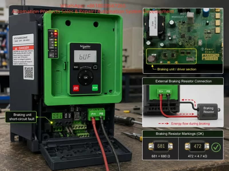
A Schneider ATV340D37N4E drive was received for repair after the customer reported a bUF braking unit short-circuit fault at the site. After the drive was brought back for bench testing, normal start and stop operation appeared to be fine. The motor could run, and no obvious abnormality was observed during ordinary operation. However, when the deceleration time was set very short, the drive triggered the braking unit short-circuit fault.
Further testing showed that this model has a parameter related to braking unit detection or braking function enablement. When this function was enabled, the drive reported a braking unit short-circuit fault during fast deceleration. When the braking function was disabled, the drive no longer generated the fault even under fast stop conditions.
At first glance, this appeared to be a typical external braking resistor fault, braking transistor fault, or braking IGBT short circuit. However, the actual repair process proved that the braking IGBT power device itself was not the root cause. The real fault was located in the DESAT detection circuit of the intelligent IGBT driver optocoupler used for the braking IGBT.
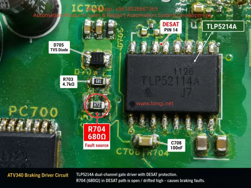
The final diagnosis confirmed that resistor R704, connected to the DESAT pin of the TLP5214A intelligent IGBT driver optocoupler, had become abnormally high resistance or open circuit. Its correct value should be 681, meaning 680Ω, but the faulty board measured more than 10MΩ, effectively open circuit. After replacing R704 with a 680Ω resistor, the braking function returned to normal, fast stop testing passed, and the bUF braking unit short-circuit fault disappeared.
This case is highly representative. It shows that when troubleshooting a braking unit short-circuit fault, technicians should not only check whether the braking IGBT is shorted with a multimeter, nor should they only focus on the external braking resistor value. In circuits using intelligent gate drivers and DESAT protection, an open, leaky, contaminated, or drifted detection circuit can also cause the drive to falsely report a braking unit short circuit.
2. Basic Working Principle of the Braking Unit
In an inverter drive such as the ATV340, when the motor decelerates a high-inertia load, the motor may act as a generator. Mechanical energy is converted into electrical energy and fed back into the DC bus through the inverter bridge. This causes the DC bus voltage to rise. If the voltage rises beyond the protection threshold, the drive will trip on DC bus overvoltage. In severe cases, power components may be damaged.
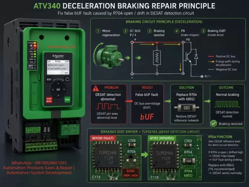
The braking unit is used to dissipate this regenerative energy. When the DC bus voltage reaches the braking threshold, the drive turns on the braking IGBT. Current flows through the external braking resistor, converting the excess electrical energy into heat.
A typical braking current path is:
P/+ DC bus positive → braking resistor → PB terminal → braking IGBT → N/- DC bus negative
When the braking IGBT is off, the PB terminal is not pulled toward N/-, and almost no braking current flows through the resistor. When the braking IGBT turns on, PB is pulled down toward N/-, current flows through the braking resistor, and the regenerative energy is dissipated.
Therefore, whether the braking unit works correctly depends on several factors:
- The resistance and power rating of the external braking resistor;
- The reliability of the P/+, PB, and N/- power connections;
- Whether the braking IGBT turns on and off correctly;
- Whether the braking IGBT gate drive is normal;
- Whether the overcurrent, short-circuit, and DESAT detection circuits are normal;
- Whether the control board correctly receives the braking unit fault feedback signal.
In practical repairs, the first two items are relatively easy to check. The third can also be roughly checked with a multimeter. However, the fourth, fifth, and sixth items require deeper understanding of the gate driver optocoupler, DESAT detection, FAULT feedback, and dynamic waveforms.
3. Common Causes of bUF Braking Unit Short-Circuit Fault
When a drive reports a braking unit short-circuit fault, the common causes can be grouped into the following categories.
3.1 External Braking Resistor Value Too Low
If the braking resistor value is lower than the minimum value allowed by the drive, the current through the braking IGBT becomes excessive as soon as the IGBT turns on. The driver or protection circuit may then immediately report a braking transistor short circuit or braking unit fault.
For a 400V-class drive, the DC bus voltage is commonly around 540V to more than 700V, especially during deceleration. If the braking resistor value is too low, the instantaneous braking current can become very high, placing excessive electrical and thermal stress on the braking IGBT.
3.2 Braking Resistor Wiring Short Circuit or Ground Leakage
Incorrect wiring between P/+ and PB, damaged braking resistor cables, carbonized terminals, loose connections, or ground leakage in the braking resistor box can all cause abnormal braking circuit behavior. In environments with moisture, dust, oil mist, or conductive contamination, insulation failure at the resistor terminals and cables is especially common.
3.3 Braking IGBT Collector-Emitter Short Circuit
This is the most direct cause. If the braking IGBT collector and emitter are shorted, PB is effectively pulled toward N/- continuously. Once the braking resistor is connected, an abnormal current path may exist from P/+ to N/- through the resistor. This type of fault can often be detected with a multimeter in diode or resistance mode.
3.4 Braking IGBT Gate Leakage or Abnormal Gate Drive
Some IGBTs do not fail as a direct C-E short. Instead, the gate insulation may degrade, the G-E path may leak, or the gate resistor, gate clamp, or turn-off circuit may become abnormal. In such cases, the IGBT may partially turn on when it should remain off, or it may fail to saturate properly when it should conduct.
These faults are not always easy to detect with a normal multimeter.
3.5 Driver Optocoupler Failure or Driver Power Supply Abnormality
Medium and high-power drives usually use isolated driver optocouplers or intelligent gate driver chips to drive IGBTs. The braking IGBT is no exception. If the driver output voltage is too low, negative turn-off voltage is abnormal, or the driver supply decoupling capacitor has failed, the IGBT may not turn on fully or may turn off incorrectly.
3.6 DESAT Detection Circuit Abnormality
This is the core issue in this case.
Many intelligent IGBT driver optocouplers include DESAT protection. DESAT detection is used to determine whether an IGBT has entered normal saturation when it is commanded to turn on. If the IGBT receives a gate drive command but the C-E voltage remains too high, it may indicate short circuit, overcurrent, insufficient gate drive, module failure, or load abnormality. The driver chip then quickly shuts down the IGBT and outputs a fault signal.
However, if the DESAT detection circuit itself is open, leaky, contaminated, drifted, or has a cracked solder joint, the driver chip may falsely detect desaturation even when the IGBT is actually normal. The result is a false braking unit short-circuit fault.
4. Diagnostic Process in This Case
4.1 Fault Condition Confirmation
The ATV340D37N4E could run normally under ordinary conditions. Normal start and stop operation did not produce any abnormal alarm. The bUF braking unit short-circuit fault appeared only when the deceleration time was set very short and the braking unit participated in energy dissipation.
This indicated that the main inverter bridge, current detection circuit, control logic, and auxiliary power supply were unlikely to be the primary fault areas. If the main inverter bridge or the main DC power stage had a serious defect, the drive would likely report overcurrent, short circuit, undervoltage, phase loss, or drive faults even during ordinary operation.
Since the fault was strongly associated with fast deceleration and braking unit activation, the diagnostic focus was shifted to the braking circuit.
4.2 External Braking Resistor Check
During bench testing, a temporary resistance wire of approximately 10Ω was connected between P/+ and PB to simulate the braking resistor, and the same fault could be reproduced. Although a temporary resistance wire is not equivalent to a standard braking resistor in every aspect, the customer’s site also reported the same fault with a standard braking resistor. Therefore, the external resistor itself was not considered the main suspect.
In real repair practice, the following items should still be checked:
- Actual braking resistor resistance;
- Whether the resistance is below the minimum value allowed by the drive;
- Braking resistor power rating;
- Wiring reliability between P/+ and PB;
- Insulation resistance of the braking resistor to ground;
- Cable damage, loose terminals, overheating, carbonization, or arcing marks.
In this case, because the same fault occurred with the customer’s standard braking resistor and the temporary resistor was only used to reproduce the fault, the investigation continued inside the drive, focusing on the braking IGBT driver circuit.
4.3 Braking IGBT Inspection
The braking IGBT module was checked using conventional methods. No obvious C-E short circuit, G-E short circuit, or severe leakage was found. Based on standard repair experience, the braking IGBT appeared normal in static testing.
However, this point must be emphasized:
A normal static IGBT test does not prove that the IGBT and its protection circuit will behave normally under dynamic braking conditions.
DESAT faults usually occur at the instant when the IGBT is driven on. Only when the braking IGBT is under high DC bus voltage, carrying braking current, and controlled by the gate driver will dynamic problems such as desaturation, insufficient drive, or detection circuit failure appear.
Therefore, relying only on a diode-mode multimeter test of the IGBT can easily lead to an incorrect conclusion.
4.4 Misleading Comparison with an ATV610 Control Board
During troubleshooting, an ATV610 control board was used for comparison. Since some ATV610 and ATV340 power boards, driver boards, and modules may look similar or share similar hardware structures, it was tempting to conclude that if the ATV610 board did not trigger the fault, the power board must be normal.
Further analysis showed that this comparison was not decisive. The ATV610 control board did not have the same braking detection or braking function logic as the ATV340. It may not have actually triggered the braking IGBT in the same way, or it may not have monitored the braking unit fault feedback in the same manner.
Therefore, the fact that the ATV610 board did not report the same fault could not be used as proof that the braking driver circuit was healthy.
This is an important lesson. Even if two drive series share similar hardware platforms, their firmware logic, alarm judgment, drive enable conditions, and fault feedback processing may be different. A drive not reporting a fault does not necessarily mean that the tested power board is fully normal.
4.5 Locking the Fault Area to the TLP5214A and DESAT Circuit
The braking driver section of the board used a TLP5214A intelligent IGBT driver optocoupler. This device is not an ordinary optocoupler. It integrates IGBT gate drive, undervoltage protection, soft shutdown, fault feedback, and DESAT detection.
Pin 14 of the TLP5214A is the DESAT detection pin. When the IGBT is turned on, the DESAT pin monitors the IGBT C-E voltage through an external diode, resistor, and capacitor network. If the detected voltage exceeds the internal threshold, the driver interprets this as IGBT desaturation, shuts down the output, and sends a fault signal through the FAULT pin.
Around the TLP5214A DESAT pin, components such as R703, R704, D705, and C708 were identified. R704 was found to be related to the DESAT path. Its measured resistance was more than 10MΩ, clearly abnormal.
To confirm the expected value, a 55kW drive driver board was used for comparison. The corresponding positions on the comparison board showed the following resistor markings:
- R704: 681, meaning 680Ω;
- R703: 472, meaning 4.7kΩ.
On the faulty board, R703 measured around 5kΩ, consistent with 4.7kΩ. However, R704 measured more than 10MΩ, completely inconsistent with the expected 680Ω. This strongly indicated that R704 was open circuit or had failed to a very high resistance.
5. Why an Open R704 Causes a Braking Unit Short-Circuit Fault
When technicians see the alarm description “braking unit short circuit,” the first reaction is often to suspect a shorted braking IGBT or shorted braking resistor. However, in a circuit using DESAT detection, the alarm name does not always mean that there is a physical short circuit. It may be the result of the intelligent driver detecting an abnormal protection condition.
Under normal operation, when the braking IGBT is turned on:
- The control board sends a braking IGBT drive command;
- The TLP5214A outputs the gate drive voltage;
- The braking IGBT turns on normally;
- PB is pulled toward N/-;
- The IGBT C-E voltage drops to a low value;
- The DESAT detection circuit confirms that the IGBT has entered saturation;
- The driver optocoupler does not output a fault signal, and braking proceeds normally.
When R704 is open:
- The control board sends a braking IGBT drive command;
- The TLP5214A outputs the gate drive;
- The braking IGBT may actually turn on normally;
- But the DESAT detection path loses its normal sampling or clamping function because R704 is open;
- The internal DESAT charging current inside the TLP5214A causes the DESAT pin voltage to rise abnormally;
- The driver falsely determines that the IGBT has not entered saturation;
- The TLP5214A shuts down the output and sends a FAULT signal;
- The control board receives the braking unit fault feedback and displays bUF / braking unit short circuit.
Therefore, the real problem in this case was not an actual shorted braking IGBT. It was a false braking unit short-circuit fault caused by an open DESAT detection resistor.
Typical characteristics of this type of fault include:
- Normal ordinary running;
- Normal ordinary stopping;
- Fault appears only when the braking unit is activated;
- Disabling the braking function makes the fault disappear;
- Braking IGBT passes static testing;
- External braking resistor is normal;
- DESAT circuit components show open circuit, drift, leakage, cracked solder joints, or contamination.
6. Repair Procedure
The final repair procedure in this case was as follows:
- Lift or remove one side of R704 and confirm its abnormal resistance;
- Compare with a similar driver board and confirm the correct value of R704 as 681, meaning 680Ω;
- Replace R704 with a 680Ω SMD resistor;
- Clean the area around TLP5214A, R703, R704, D705, and C708;
- Reflow or resolder relevant TLP5214A pins, especially DESAT, VOUT, VCC2, VE, and VEE pins;
- Check connector S23 and its solder joints to ensure reliable connection to the braking IGBT circuit;
- Reassemble and test the drive;
- Enable the braking function, perform fast deceleration testing, and verify that the bUF fault no longer appears.
After R704 was replaced, the drive passed fast stop testing. The braking unit worked normally, and the fault was eliminated.
7. Key Measurement Points for Similar Faults
For similar braking unit short-circuit faults, the following diagnostic sequence is recommended.
7.1 External Braking Resistor
Measure the resistance between P/+ and PB. Confirm that the resistor value is not below the minimum allowed value for the drive. Also inspect the resistor box, cable, terminals, and insulation to ground.
7.2 Static Test of the Braking IGBT
After power is removed and the DC bus capacitors are fully discharged, check the braking IGBT C-E, G-E, and G-C paths for short circuit or leakage. If an obvious short circuit is present, the power device must be handled first.
7.3 Gate Drive Voltage
Under safe test conditions, observe the braking IGBT G-E voltage at the instant of braking. During conduction, a gate drive voltage of around +15V is typically expected. During turn-off, the voltage may be 0V or negative depending on the driver design.
7.4 TLP5214A FAULT Pin
Observe whether the FAULT pin of the TLP5214A changes state when the fault occurs. If the FAULT pin is pulled low, the driver itself has detected an abnormal condition. If the FAULT pin does not change but the control board still reports a braking unit fault, then the control board’s fault feedback input circuit should be checked.
7.5 DESAT Pin and Peripheral Circuit
Focus on the DESAT-related components connected to pin 14 of the TLP5214A, including the series resistor, sampling diode, blanking capacitor, clamping components, and solder joints. In this case, R704 was the key component.
7.6 Connectors and Solder Joints
The braking IGBT driver signal is often transmitted through a small connector. Loose connectors, cracked solder joints, oxidation, poor contact, or damaged harnesses may cause abnormal gate drive or abnormal detection signals.
8. Why a Small Resistor Can Cause a Major Fault
R704 is only a small SMD resistor with a value of 680Ω. However, because it is located in the DESAT detection path of the braking IGBT driver, it has a critical protection role.
A drive protection system does not only determine whether a large power device is physically shorted. It depends on many small signal detection circuits to judge whether the power stage is operating safely.
In the high-voltage, high-current, and high-dv/dt environment of a variable frequency drive, the intelligent driver optocoupler must quickly determine whether the IGBT is healthy during turn-on. If the DESAT circuit becomes abnormal, the driver will prioritize protection and shut down the IGBT, even if the result is a false alarm.
When a 680Ω resistor becomes open circuit, the braking IGBT may still be good, and the external braking resistor may also be normal. However, because the driver cannot receive correct DESAT information, the system reports a braking unit short circuit.
If the technician only follows the literal meaning of the alarm and repeatedly replaces the IGBT module or suspects the external resistor, the repair will go in the wrong direction.
9. Diagnostic Logic for Similar Braking Faults
When handling braking-related faults on Schneider ATV340, ATV630, ATV930, ATV610, or similar drives, the following logic is useful.
9.1 Is the Fault Strongly Related to Braking Action?
If the fault appears only during fast stop, regenerative operation, DC bus voltage rise, or braking resistor operation, the braking unit should be the first diagnostic target.
9.2 Does the Fault Disappear When Braking Is Disabled?
If disabling the braking function makes the fault disappear, the problem is related to braking IGBT drive or detection. However, this does not mean the drive can be safely returned to the customer with the braking function disabled. The customer’s load may require braking resistor operation to prevent DC bus overvoltage.
9.3 Is a Normal Static IGBT Test Sufficient?
No. A normal static test only rules out obvious breakdown. It does not rule out dynamic desaturation, insufficient drive, false detection, or DESAT circuit open faults.
9.4 Is There a Similar Board for Comparison?
If a similar power driver board is available, compare DESAT circuit resistor values, diode direction, capacitor placement, and component markings. In this case, comparison with a 55kW driver board helped confirm that R704 should be 681 rather than a high-resistance value.
9.5 Is There Contamination, Moisture, or Solder Cracking?
DESAT detection is a high-speed protection signal circuit. Board contamination, flux residue, moisture, carbonization, and cracked solder joints can all cause false triggering. Cleaning, drying, and resoldering are often necessary.
10. Suggested Technical Repair Report
The repair conclusion for this case can be written as follows:
The Schneider ATV340D37N4E drive reported a bUF braking unit short-circuit fault during fast deceleration. Inspection confirmed that the external braking resistor wiring method was correct, and the braking IGBT module showed no obvious C-E short circuit or G-E short circuit. Further inspection of the braking IGBT driver circuit found an abnormality in the DESAT detection circuit of the TLP5214A intelligent IGBT driver optocoupler. The resistor R704 connected to the DESAT circuit of pin 14 had drifted to an abnormally high resistance, measuring more than 10MΩ. On a similar driver board, the corresponding component value was 681, meaning 680Ω. The open R704 caused the DESAT detection signal to become abnormal when the braking IGBT was triggered. As a result, the driver optocoupler falsely detected IGBT desaturation or short circuit and sent a FAULT signal to the control board, triggering the bUF braking unit short-circuit alarm. After replacing R704 with a 680Ω resistor and cleaning/resoldering the related driver detection circuit, the braking function and fast deceleration operation returned to normal.
11. Conclusion
The bUF braking unit short-circuit fault on a Schneider ATV340 drive does not always mean that the braking IGBT is physically shorted. In circuits using intelligent IGBT driver optocouplers such as the TLP5214A, an abnormal DESAT detection circuit can also trigger the same alarm.
The key features of this case were: the fault appeared only when braking was enabled and fast deceleration was performed; the braking IGBT passed static testing; the external braking resistor condition could not explain the fault; and comparison with a similar driver board showed that R704 should be 680Ω, while the faulty board measured more than 10MΩ. After replacing R704, the drive returned to normal.
This case reminds repair technicians that VFD power-stage fault diagnosis should not focus only on large power components. In many cases, the component that actually triggers the alarm is a small part of the drive, protection, feedback, or detection circuit. DESAT resistors, sampling diodes, blanking capacitors, driver optocouplers, FAULT feedback circuits, and connector solder joints can all determine whether the braking unit operates correctly.
A correct repair approach should begin by confirming the fault trigger condition, then distinguishing between a real power-stage fault and a false detection fault, and finally verifying the driver optocoupler and protection circuit point by point. Only by understanding the braking unit operating principle and DESAT protection mechanism can technicians avoid unnecessary module replacement and improve repair accuracy.