
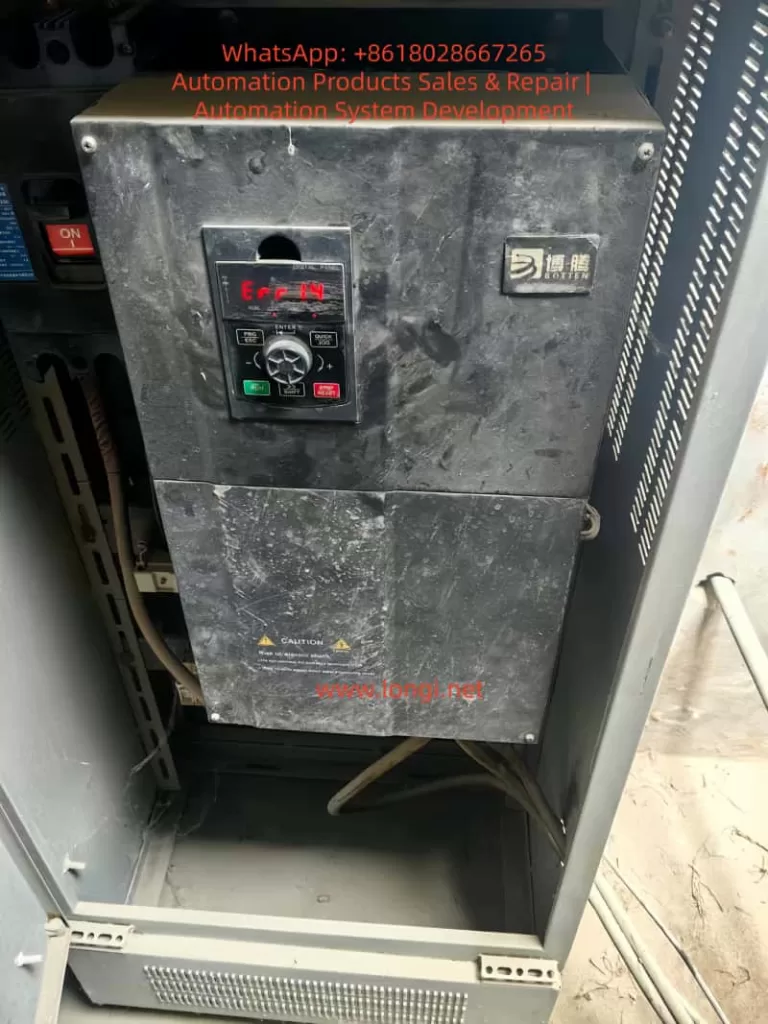
In industrial applications, faults that occur only after a period of normal operation are often more difficult to diagnose than immediate startup errors. The ERR14 fault on the BOTten BT500 series inverter is a typical example. Many engineers simply interpret it as “motor overload,” but the actual root causes are usually more complex.
This article provides a systematic and engineering-oriented analysis of the ERR14 fault, including its underlying mechanism, typical triggers, and practical troubleshooting methods.
1. Definition of ERR14 Fault
ERR14 indicates a motor overload protection fault.
It is important to distinguish this from overcurrent faults. ERR14 is not triggered by a short-term current spike. Instead, it is based on an electronic thermal model inside the inverter, which simulates the heating process of the motor.
The inverter continuously calculates:
- Motor current
- Time duration
- Thermal accumulation
When the accumulated thermal value exceeds a predefined threshold, the inverter trips and reports ERR14.
2. Why the Fault Occurs After One Hour of Operation
This is a key characteristic of ERR14.
The fault is triggered by thermal accumulation over time, not instantaneous conditions.
The internal logic can be summarized as follows:
- Higher current leads to faster heat generation
- Longer operation leads to greater heat accumulation
- When the thermal limit is exceeded, protection is triggered
This explains the typical behavior:
- The system runs normally at startup
- After tens of minutes or about one hour, the fault occurs
This type of issue is essentially a chronic overload condition, not an immediate failure.
3. Five Primary Causes of ERR14 Fault
3.1 Excessive Mechanical Load (Most Common)
This is the most frequent cause in real-world applications.
Typical scenarios include:
- Increased mechanical resistance (bearing wear, misalignment, or jamming)
- Process changes (blocked pump, increased airflow resistance in fans)
- Long-term operation near or above rated load
Observed behavior:
- Normal operation at the beginning
- Gradual increase in current
- Eventual overload trip
3.2 Incorrect Motor Parameter Settings
If the motor parameters configured in the inverter are inaccurate, the inverter may misjudge the load condition.
Common issues include:
- Rated current set too low
- Incorrect motor power rating
- Wrong number of poles
As a result:
- The inverter may trigger overload protection prematurely
- Or fail to reflect the actual operating condition
3.3 Over-Sensitive Overload Protection Settings
The key parameter is:
- F9-01: Motor Overload Protection Gain
This parameter determines how quickly the inverter interprets a condition as overload.
If set too low:
- Even moderate load levels may be treated as overload
- Fault occurs after a period of operation
3.4 Poor Cooling Conditions
From typical field conditions, many units suffer from:
- Heavy dust accumulation
- Poor cabinet ventilation
These factors cause:
- Increased internal temperature of the inverter
- Reduced cooling efficiency of the motor
Resulting in:
- Lower effective current capacity
- Faster thermal accumulation
- Increased likelihood of ERR14
3.5 Low-Speed High-Torque Operation
At low frequency operation:
- Motor speed is low
- Cooling fan efficiency decreases
- Torque demand remains high
This leads to:
- Increased current
- Rapid heat buildup
- Higher risk of overload trip
4. Standard Troubleshooting Procedure
The following step-by-step process can be directly applied on site.
Step 1: Check Operating Current
Use the inverter monitoring interface to read:
- Actual running current
- Motor rated current
Evaluation:
- Above rated current: real overload
- Near rated current: critical condition
- Well below rated current: parameter or protection issue
Step 2: Inspect Mechanical System
Check for:
- Bearing overheating
- Mechanical jamming
- Excessive coupling tension
- Blockage in pumps or fans
In many cases, the root cause is mechanical rather than electrical.
Step 3: Verify Motor Parameters
Ensure the following match the motor nameplate:
- Rated voltage
- Rated current
- Rated power
Incorrect parameters directly affect overload judgment.
Step 4: Optimize Overload Protection Parameters
Recommended adjustments:
- F9-01: increase from 1.0 to 1.2–1.5
- F9-02: increase to around 90%
Important:
- Do not increase excessively
- Over-adjustment may eliminate necessary protection
Step 5: Improve Cooling Conditions
Required actions:
- Clean internal and external dust
- Ensure cooling fans are operational
- Improve cabinet ventilation
- Avoid heat accumulation
Step 6: Analyze Operating Conditions
Check whether the system is:
- Running at low frequency for long periods
- Operating under high load continuously
If so:
- Increase operating frequency where possible
- Reduce load if feasible
Step 7: Evaluate Inverter Sizing
If the system operates near full load continuously:
- The inverter may be undersized
Recommended action:
- Upgrade to a higher power rating
5. Typical Fault Patterns
Case A
- Fault occurs after a period of operation
- Current near rated value
- Visible dust accumulation
Conclusion:
- Mild overload combined with poor cooling
Case B
- Current is low
- Fault still occurs
Conclusion:
- Incorrect parameter configuration
Case C
- Fault occurs at a consistent time interval
Conclusion:
- Thermal model accumulation triggering protection
6. Engineering-Level Solutions
Solution 1: Reduce Mechanical Load
- Eliminate unnecessary resistance
- Optimize process conditions
Solution 2: Adjust Protection Parameters
Recommended setting:
- F9-01 = 1.3
- F9-02 = 90%
Solution 3: Correct Motor Parameters
- Input accurate nameplate data
- Perform motor auto-tuning if available
Solution 4: Enhance Cooling System
- Clean dust
- Add ventilation or fans
- Improve airflow path
Solution 5: Upgrade Equipment
If operating current exceeds 80% of rated value continuously:
- Replace with a higher capacity inverter
7. Conclusion
The ERR14 fault is not simply a “motor problem” or “inverter failure.” It is a system-level issue involving:
- Electrical load
- Thermal accumulation
- Mechanical conditions
A delayed fault occurrence indicates that the system is operating near its thermal limit over time.
To fully resolve the issue, engineers must address three key aspects:
- Mechanical load
- Electrical parameter configuration
- Cooling conditions
Only when all three are properly matched can ERR14 faults be completely eliminated in long-term operation.