
Root Cause Analysis and Systematic Troubleshooting of “Sample Not Detected (ID:32)” Error
1. Introduction: A Frequently Misdiagnosed “Fault”
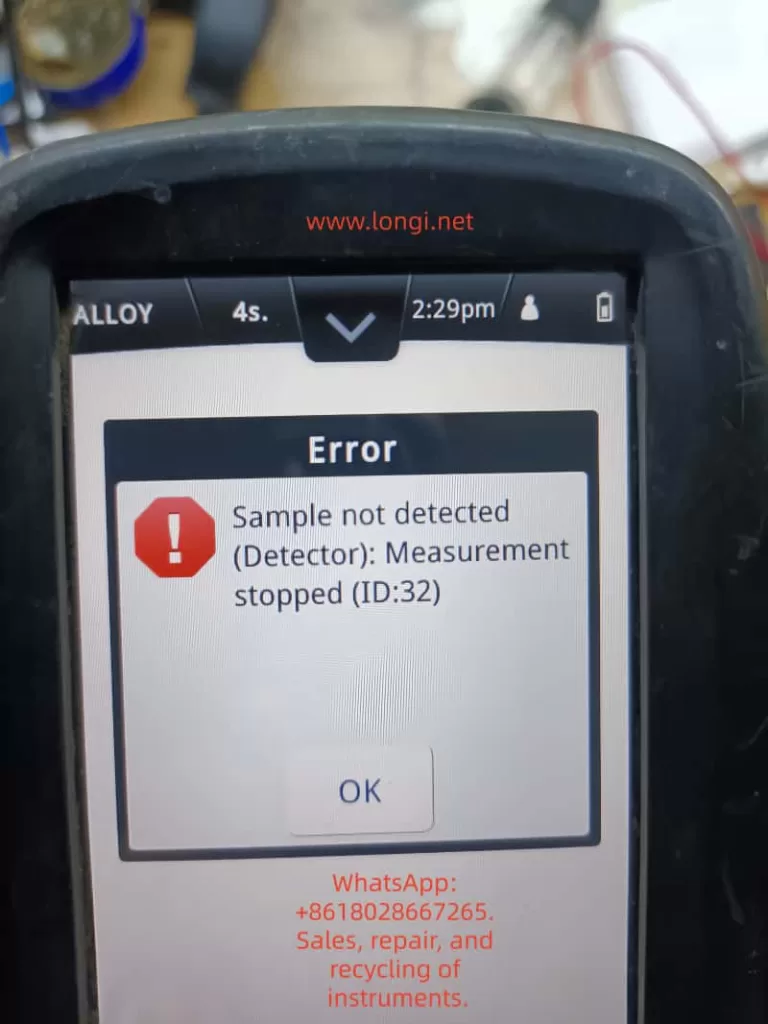
In practical field applications of handheld XRF (X-ray Fluorescence) analyzers, the message:
“Sample not detected (Detector): Measurement stopped (ID:32)”
is one of the most commonly encountered prompts.
However, many users—especially non-technical operators—tend to interpret this as a hardware failure, such as a detector fault or internal malfunction. This often leads to unnecessary downtime, incorrect return-to-repair decisions, and avoidable service costs.
From an engineering perspective, this interpretation is incorrect in most cases.
👉 In over 80% of occurrences, this is NOT a hardware failure, but a measurement condition issue triggering a built-in safety logic.
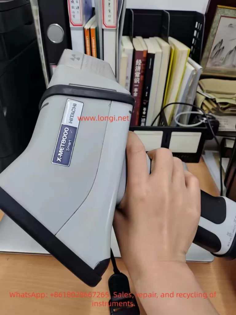
This article provides a structured, technical analysis of the ID:32 error based on the X-MET8000 platform and offers a systematic troubleshooting methodology suitable for:
- Field engineers
- Technical support teams
- Equipment maintenance personnel
- Industrial users
2. Fundamentals of XRF Measurement (Prerequisite Understanding)
To properly understand this error, one must first understand how XRF analyzers work.
2.1 Basic Measurement Process
A handheld XRF analyzer operates through the following sequence:
- The X-ray tube emits primary X-rays
- The sample is excited and emits characteristic secondary X-rays (fluorescence)
- The detector captures the emitted fluorescence
- The system analyzes the energy spectrum to determine elemental composition
2.2 Conditions Required for Valid Measurement
For a successful measurement, the following conditions must be satisfied:
- Proper physical contact between probe and sample
- Sample must have sufficient size and thickness
- Detector must receive adequate fluorescence signal intensity
- Safety interlock (contact/proximity sensor) must be activated
If any of these conditions fail, the instrument will automatically terminate the measurement.
3. Technical Interpretation of ID:32 Error
3.1 Error Message Breakdown
Sample not detected (Detector)
Measurement stopped (ID:32)
| Component | Meaning |
|---|---|
| Sample not detected | No valid sample signal detected |
| Detector | Detector failed to receive sufficient signal |
| Measurement stopped | System aborted measurement |
| ID:32 | Internal diagnostic code |
3.2 Engineering Definition
👉 ID:32 = Sample Detection Failure
More precisely:
The detector did not receive sufficient fluorescence signal above the threshold, or the contact detection system was not properly triggered, resulting in automatic measurement termination.
3.3 Internal Trigger Mechanisms
The X-MET8000 typically relies on two parallel validation mechanisms:
① Signal Threshold Validation
- The detector evaluates whether the incoming fluorescence signal exceeds a predefined minimum threshold
- If the signal resembles background radiation (i.e., air), it is classified as “no sample”
② Contact Safety Interlock
- The probe includes a contact or proximity sensor
- X-ray emission is restricted or stopped unless proper contact is detected
👉 If either condition is not met → ID:32 is triggered
4. Seven Common Causes of ID:32 (Ranked by Probability)
4.1 Poor Probe Contact (Most Common, >50%)
Symptoms:
- Gap between probe and sample surface
- Unstable hand positioning
Technical Cause:
- X-ray scattering increases
- Fluorescence signal fails to return efficiently
Solution:
- Press the analyzer firmly against the sample
- Maintain perpendicular alignment
4.2 Measuring Air / No Sample
Symptoms:
- Analyzer not properly aligned
- Measurement triggered without a sample
Cause:
- Detector only receives environmental background
4.3 Sample Too Small
Typical Cases:
- Screws, wires, narrow tubes
- Irregular edges
Issue:
- Insufficient surface coverage
- Increased background interference
Solution:
- Place sample on a solid metal backing
- Use a sample holder
4.4 Sample Too Thin or Low Density
Examples:
- Foils
- Coated materials
- Loose powders
👉 Leads to insufficient fluorescence signal
4.5 Surface Contamination (Critical)
Types:
- Oil
- Paint
- Oxidation
- Rust
👉 Effects:
- X-ray attenuation
- Signal distortion or reduction
4.6 Detector Window Contamination
Common issues:
- Metal dust accumulation
- Oil residue
- Protective film damage
👉 Directly reduces detection efficiency
4.7 Contact Sensor Malfunction (Low Probability)
Symptoms:
- Error persists even with proper contact
- Occurs across multiple samples
Possible causes:
- Sensor failure
- Mechanical wear
- Internal wiring issues
5. Systematic Troubleshooting Procedure
This structured workflow is suitable for both remote support and on-site diagnostics.
Step 1: Reference Sample Test (Critical)
Use:
👉 A solid stainless steel or steel block
Procedure:
- Press firmly
- Maintain stable contact
Interpretation:
| Result | Conclusion |
|---|---|
| Measurement successful | Not a device issue |
| Error persists | Continue troubleshooting |
Step 2: Inspect Detector Window
Check for:
- Dirt or contamination
- Damage or obstruction
Step 3: Verify Contact Condition
- Apply firm pressure
- Adjust angle if necessary
Step 4: Test Different Samples
Purpose:
- Eliminate sample-related factors
Step 5: Restart Device
To rule out:
- Temporary software anomalies
Step 6: Hardware Diagnosis (Final Stage)
If all above fail, consider:
- Detector failure
- Contact sensor malfunction
- Internal electronics issue
6. Common Misdiagnosis Cases
Case 1: “Detector Failure” Misjudgment
Actual issue:
- Painted surface measured
👉 Root cause: Surface contamination
Case 2: Small Component Measurement Failure
Actual issue:
- Sample size insufficient
👉 Solution:
- Use metal backing
Case 3: Repeated Error in Field
Actual issue:
- Detector window covered with metal dust
7. Preventive Best Practices
7.1 Proper Operation
- Maintain firm, stable contact
- Avoid movement during measurement
7.2 Sample Preparation
- Clean surface
- Remove coatings
- Polish if necessary
7.3 Use Accessories
- Sample holders
- Measurement stands
7.4 Routine Maintenance
- Clean detector window regularly
- Inspect protective film
8. Technical Support Strategy
When assisting customers:
1️⃣ Always rule out operational issues first
Avoid premature hardware conclusions
2️⃣ Guide standardized testing
Ask customer to use a solid metal reference sample
3️⃣ Provide structured instructions
Avoid vague or generic advice
9. Final Summary
The ID:32 error should not be interpreted as a fault, but as a measurement condition failure.
From a technical standpoint:
It indicates insufficient signal or improper sample contact—not equipment damage.
Key Statistics:
- >80% cases: Operational or sample-related
- <10% cases: Actual hardware issues
10. Engineering Conclusion
👉 The “Sample not detected (ID:32)” message in X-MET8000 is:
- A normal protective mechanism
- A standard behavior in XRF systems
- Fully avoidable through proper operation