
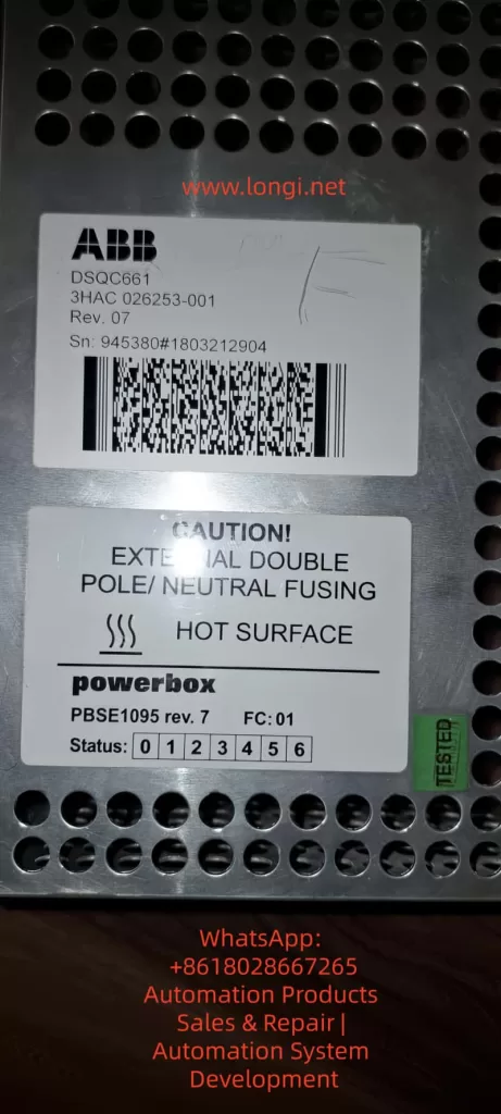
The Switched-Mode Power Supply (SMPS) is one of the core components of an industrial robot control system. In the ABB IRC5 series robot control cabinets, the DSQC661 (Powerbox PBSE1095 rev.7) serves as the system power module, responsible for converting 230V AC input into a stable 24V DC output with a rated current of up to 27A and a total power of approximately 648W. This module powers the control panel, I/O boards, computer units, and safety circuits exclusively. Once a “No output” fault occurs, the entire control cabinet cannot be energized, causing the robot system to shut down.
This article uses a real fault case provided by a user (the module has no output after being connected to the control panel; the user suspects the large yellow transformer is damaged) as the starting point. It systematically explains the SMPS working principle, common failure modes, diagnostic procedures, maintenance techniques, and prevention strategies. The content is based on ABB official manuals, general SMPS topology analysis, and practical maintenance experience. It does not rely on public schematics (ABB classifies internal circuit diagrams as proprietary) but achieves precise localization through circuit topology reasoning and component-level testing. The full text focuses on technical details without any redundant descriptions.
I. Role of SMPS in Industrial Robots and DSQC661 Specifications
Industrial robot control cabinets have extremely high requirements for power supplies: high efficiency (>85%), low ripple (<100mV), strong anti-interference capability, and strict isolation safety. Traditional linear power supplies are bulky and generate severe heat, having been completely replaced by SMPS. The DSQC661 adopts an offline topology, first using a bridge rectifier to generate a DC bus voltage of approximately 325V, then achieving isolated step-down through high-frequency switching (typically 50-100kHz).
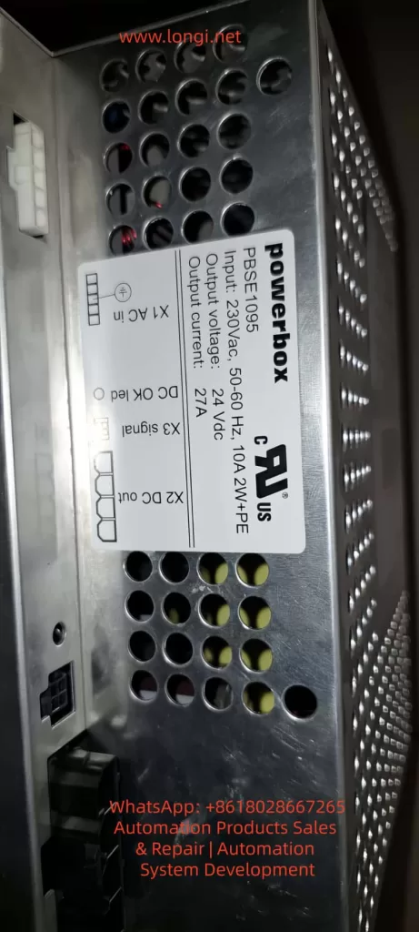
Key Specifications (extracted from module labels and ABB product manuals):
- Input: 230V AC ±10%, 50-60Hz, 10A, 2W+PE (with protective earth).
- Output: 24V DC ±5%, 27A continuous, with brief peak overload capability.
- Efficiency: Typically 88-92% (full load).
- Protection: Input bipolar fusing, output overvoltage/overcurrent/short-circuit protection, over-temperature shutdown.
- Indicators: Front panel status LEDs (bits 0-6), DC OK LED (lights up when X2 output is normal), X3 signal interface.
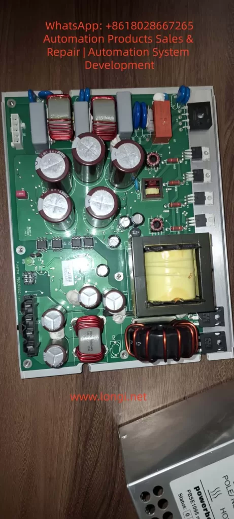
- Physical: Aluminum housing with ventilation holes; internal PCB contains large-capacity electrolytic capacitors, main transformer (yellow epoxy potted, square core), output choke, and multiple MOSFETs.
Power Calculation Example:
Output power Pout=Vout×Iout=24×27=648W.
Considering efficiency η=90%, input power is approximately 720W, and input current Iin≈720/230≈3.13A (actually higher due to PFC). Ripple requirements are strict, typically ΔV<50mV, to avoid affecting robot safety circuits.
The DSQC661 internally uses a typical Forward Converter or Half-Bridge topology, rather than a simple Flyback.
- Reason: An output current of 27A is medium-to-high power; Flyback is suitable for <200W. The Forward Converter provides low ripple and high efficiency through secondary-side inductance filtering.
- Main Transformer: The large yellow block in photos is a high-frequency isolation transformer. The primary winding withstands 325V pulses, and the secondary multi-output is rectified by Schottky diodes.
Forward Converter Core Equation:
- Output voltage Vout=Vin×D×NpNs, where D is the duty cycle (typically 0.2-0.4).
- Transformer reset requires a third winding or an RCD clamp circuit (red small capacitor + diode commonly seen in photos).
II. DSQC661 Typical Failure Modes and “No Output” Cause Analysis
The symptom “no output after connecting to the control panel” in the user’s case is the most common. Possible causes ranked by probability:
- Input Side Failure (Highest probability, ~40%): Fuse blown, bridge rectifier diode shorted, PFC circuit (if present) damaged. Check if terminal X1 AC in has 230V and if the fuse is intact.
- Main Electrolytic Capacitor Aging (Probability 30%): Input filter capacitors (multiple large-capacity 450V aluminum electrolytic capacitors in photos) and output filter capacitors (low-voltage large-capacity) bulge, leak, or have increased ESR due to high temperature and ripple current. Bulging capacitors cause unstable bus voltage, leading to overvoltage breakdown of switching tubes and ultimately no output.
- Main Transformer Failure (User’s suspicion, Probability 15%): Insulation breakdown, winding short circuit, or open circuit of the yellow potted transformer. Long-term overload or dust causes partial discharge; insulation resistance between primary and secondary <1MΩ results in failure. Symptoms: Input voltage present but no switching ringing sound; transformer heats up or smells burnt.
- Switching Devices and Control Circuit (Probability 10%): MOSFET/IGBT breakdown, PWM controller IC (UC384x series or similar) damaged, feedback optocoupler aged. PWM drive signal is 0V when there is no output.
- Load Side Short Circuit Protection (Probability 5%): Internal short circuit in the control panel triggers output protection. No-load testing is required.
- Others: Output diode short circuit, over-temperature protection lockout, control chip supply missing.
Measured Data: Normal no-load output is 24.0-24.5V; ripple under load <100mV. If output is 0V or <1V, it is a “dead” fault.
III. Complete Diagnostic Procedure (Recommended 8-Step Method)
Step 1: Safety Preparation
Power off for 10 minutes. Discharge all large capacitors using a 1kΩ/5W resistor (bus voltage can reach 325V DC). Wear an anti-static wrist strap. Prepare a Digital Multimeter (DMM), oscilloscope, insulation resistance tester (Megger), and LCR meter.
Step 2: Visual and LED Inspection
Inspect PCB: Are capacitors bulging? Does the transformer have cracks or burn marks? Is the PCB carbonized?
Front Panel LEDs: Is DC OK lit? What value do status bits 0-6 show? (In ABB manuals, 0 means normal; 1-6 are specific error codes).
Step 3: No-Load Independent Test
Disconnect all loads from X2 DC out, connect only 230V AC.
- Measure X2 output: Should be 24V DC.
- If still no output, the fault is in the power supply itself; if there is output, the load is shorted.
Step 4: Input Side Test
- Measure voltage at X1 AC in terminals (L-N ≈230V, L-PE ≈230V).
- Check input fuses (internal or external).
- Voltage across the bus capacitor after rectification should be ≈325V DC (no load).
Step 5: Capacitor and ESR Test
Use an LCR meter to measure ESR of large capacitors (Normal <0.1Ω, high-voltage capacitor <0.05Ω). Bulging capacitors with ESR >1Ω need replacement.
- Formula: Ripple current Irms=IoutD(1−D). Aging accelerates failure due to heat.
Step 6: Transformer Special Test (Targeting user’s suspicion)
- Resistance Method: Primary winding resistance ≈ several to十几 ohms, secondary <1Ω. Open circuit is infinite; short circuit is near 0Ω.
- Insulation Test: Primary-secondary, primary-ground, and inter-winding insulation measured with 500V Megger should be >10MΩ.
- Ring Test: Inject a pulse into the primary using an oscilloscope + signal generator and observe the decay waveform. Normal damped oscillation >10 cycles; short circuit causes waveform collapse.
- Turns Ratio Verification: If an oscilloscope is available, measure the primary/secondary voltage ratio under low-voltage testing.
Step 7: Switching Circuit Dynamic Test
After powering on (with a current-limiting bulb in series for protection), use an oscilloscope to measure the MOSFET gate drive waveform (should be a 10-15V square wave). If no drive, check the PWM IC supply (usually 12-15V auxiliary power).
Step 8: Load Test and Thermal Imaging
Connect a 24V/10A dummy load and monitor temperature (Transformer <80°C, Capacitor <60°C). Use a thermal camera; hot spots indicate the fault point.
If the above steps still fail to locate the fault, it is recommended to send it to an ABB authorized service station (they hold complete schematics) or a professional SMPS repair shop.
IV. Maintenance Operation Standards and Component Replacement Guide
- Capacitor Replacement: Prioritize 105°C/2000 hours or longer life models (e.g., Rubycon, Nippon Chemi-Con). Low-voltage large-capacity capacitors on the output side require low ESR series. Use a hot air gun (350°C) for soldering to avoid overheating the PCB.
- Transformer Repair or Replacement: If the winding is open, rewinding can be attempted (requires professional equipment to measure turns); insulation breakdown usually requires replacing the whole unit. Pay attention to the yellow potting glue; soften it with isopropanol when disassembling.
- MOSFET Replacement: Select the same model or higher voltage rating (≥600V, Rds(on)<0.5Ω). Gate drive parameters must match, and parallel Zener diodes and gate resistors must be replaced.
- PWM IC and Optocoupler: Commonly UC3843/3845 or VIPer series. After replacement, the feedback loop (resistor divider + TL431) needs calibration.
- Post-Assembly Testing: First no-load, then gradually increase load to 27A. Monitor ripple: Vripple=f×CIout×D (C is output capacitance). After passing, connect to the robot control panel.
Tool List: Multimeter, Oscilloscope (≥100MHz), Hot air gun, Desoldering pump, Insulation tester, Dummy load (24V power resistor or electronic load).
V. Preventive Maintenance and Reliability Improvement Strategies
- Regular Inspection: Check capacitor appearance every 6 months, clean ventilation holes, and measure output ripple.
- Environmental Control: Cabinet temperature <45°C; avoid dust (common in robot workshops). Install additional fans or filter screens.
- Load Management: Avoid long-term full load; add fuses before control panel short circuits.
- Upgrade Solutions: If failures are frequent, consider third-party compatible 24V 30A industrial SMPS (need to verify isolation and signal compatibility) or upgrade to the latest rev.8 version.
- Life Prediction: Capacitor life formula L=L0×2(T0−T)/10 (Arrhenius model); life halves for every 10°C rise in temperature.
VI. Real Case Review and Precautions
- Case 1: DSQC661 in an IRC5 cabinet at an automotive factory had no output. Diagnosis revealed all main filter capacitors were bulging. Restored after replacement. Root Cause: Cabinet temperature was constantly 55°C.
- Case 2: Transformer insulation breakdown; user smelled a burnt odor. Confirmed by Ring Test and replaced the whole unit; system restarted normally.
- Case 3: Load short-circuit protection falsely triggered. After no-load testing, a capacitor short on the control panel I/O board was found.
⚠️ Safety Warning:
- Must discharge before working on the high-voltage side.
- High-voltage withstand test must be performed after maintenance (>1.5kV AC for 1 minute).
- Non-professionals are strictly prohibited from attempting this to avoid electric shock or damage to robot safety circuits.
VII. Conclusion and Resource Recommendations
80% of DSQC661 “no output” faults can be located through visual inspection + multimeter + no-load testing. The transformer is not the most common culprit; capacitor aging and switching tube failures are more prevalent. Mastering Forward Converter topology and component-level diagnosis enables efficient maintenance and reduces downtime losses.