
Abstract
In the field of modern industrial automation, Variable Frequency Drives (VFDs) serve as the core equipment for motor control, and their stable operation directly impacts production efficiency and equipment lifespan. The Parker AC10 series inverter is renowned for its simplicity, reliability, and cost-effectiveness, widely used in applications such as fans, pumps, and conveyors. However, the LU fault code (Under-Voltage Protection) is one of the most common issues in this series, often causing equipment downtime. This article begins with the fundamental principles of inverters, provides a detailed analysis of the specifications and internal structure of the Parker AC10 series, and delves into the causes, diagnostic methods, and resolution strategies for LU faults. Through real case studies and preventive maintenance recommendations, it offers comprehensive technical guidance to help engineers solve problems efficiently. The article emphasizes safe operation and parameter optimization in practical application scenarios, aiming to enhance VFD maintenance standards.
Introduction
With the advancement of Industry 4.0, the role of inverters in energy saving, emission reduction, and precision control has become increasingly prominent. According to data from the International Energy Agency (IEA), motor systems consume approximately 46% of the world’s electricity, and inverters can save 20%-30% of this energy. As a global leader in motion and control technology, Parker Hannifin’s AC10 series inverter stands out for its compact design and user-friendly interface. However, in actual operation, faults are inevitable. Among them, the LU fault code is one of the most common protection mechanisms, representing under-voltage protection.
The occurrence of an LU fault usually stems from abnormal input voltage; if not addressed promptly, it can trigger chain reactions such as motor overheating or system collapse. Based on Parker’s official manuals, technical literature, and field experience, this article systematically expounds on the diagnosis and troubleshooting of LU faults. The structure includes inverter fundamentals, an overview of the AC10 series, fault details, cause analysis, diagnostic steps, case studies, preventive measures, and advanced topics. Through a logically rigorous narrative, it ensures readers can fully grasp the relevant knowledge from theory to practice.
Inverter Fundamentals
Definition and Working Principle of Inverters
An inverter is a power electronic device used to control the speed and torque of an AC motor. It achieves flexible drive of the motor by changing the output voltage and frequency. The basic structure includes a rectifier unit, a filter unit, an inverter unit, and a control unit.
- Rectifier Unit: Converts input AC power into DC power, typically using a diode bridge rectifier. For a three-phase input, the output DC voltage (DC Bus) is approximately 1.414 times the input line voltage. For example, with a 380V input, the DC Bus is approximately 537V.
- Filter Unit: Uses large-capacity electrolytic capacitors to smooth the DC voltage and reduce ripple. Under-voltage faults are often related to this unit; if the capacitor ages or the input voltage is insufficient, the DC Bus voltage will drop below the threshold.
- Inverter Unit: Uses power devices such as IGBTs or MOSFETs to invert the DC power into adjustable frequency AC power for output to the motor.
- Control Unit: Based on a microprocessor, it implements algorithms such as vector control and V/F control. The Parker AC10 supports sensorless vector control, providing precise torque response.
The protection functions of an inverter are crucial, including Over-Current (OC), Over-Voltage (OE), Overload (OL), and Under-Voltage (LU). LU protection is a safety mechanism that triggers when the DC Bus voltage falls below a set threshold to prevent equipment damage caused by operation under low voltage.
Application of Inverters in Industry
In the manufacturing industry, inverters are widely used for constant pressure water supply, fan speed regulation, and conveyor belt control. For example, in the textile industry, the AC10 can precisely control the speed of a spinning machine to reduce yarn breakage. Under-voltage faults occur frequently in areas with unstable power grids, such as remote factories or during peak electricity usage periods, leading to production interruptions. Understanding the basic principles helps in quickly locating the problem.
Overview of the Parker AC10 Series
Product Specifications and Features
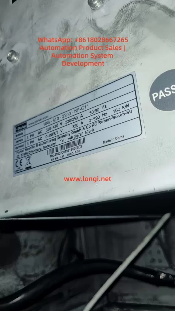
The Parker AC10 series is an economical compact inverter with a power range from 0.2kW to 180kW (IP20 protection level) or 0.4kW to 90kW (IP66). It supports single-phase 230V, three-phase 230V, or 380-480V input voltage, with an output frequency of 0-400Hz. Key specifications include:
| Parameter | Specification Description |
|---|---|
| Input Voltage | 3-phase 380-480V (+10%/-15%) |
| Output Power | 0.2-180kW |
| Overload Capacity | 150% for 1 minute, 180% for 2 seconds |
| Control Mode | V/F, Sensorless Vector |
| Protection Function | IP20/IP66, Built-in EMC Filter |
| Interface | RS485 Modbus, Keypad Display |
The AC10 adopts a modular design, with internal circuits including a power board, a control board, and a drive board. The power board is responsible for rectification and filtering, while the control board processes signals and parameters. Features include a built-in PID controller, auto-tuning, and display of up to 15 fault codes.
Internal Circuit Structure
The internal circuit of the AC10 focuses on efficiency and reliability. The input passes through an EMI filter to a rectifier bridge (typically 6 diodes) to generate the DC Bus. Electrolytic capacitors (typically rated for 450V) store energy, and an IGBT module inverts the output. A voltage sampling circuit monitors the DC Bus in real-time; if it falls below the threshold (approximately 320-340V for 380V models), it triggers an LU fault.
A control chip (such as the STM32 series) processes the fault logic. Common components on the power board include relays (HF105F), transformers, and resistor voltage divider networks. Loose connections often occur between these components, causing intermittent under-voltage.
Detailed Explanation of LU Fault Code
Meaning of the LU Code
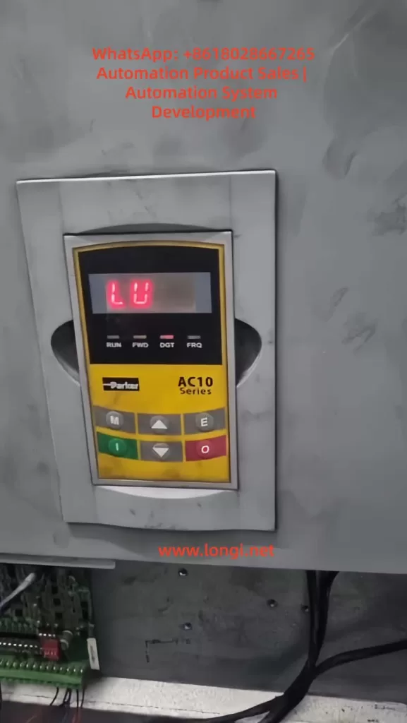
In the Parker AC10 series, LU stands for “Low Voltage” or “Under Voltage,” i.e., under-voltage protection. When the inverter detects that the input voltage or DC Bus voltage is below the safety threshold, it displays LU and stops output. This is an active protection mechanism to avoid IGBT damage or motor loss of control when operating under low voltage.
According to the manual, the LU trigger threshold is usually 85%-90% of the input voltage. For example, in a 380V system, the threshold is approximately 320V. The fault code is displayed on the LED panel, accompanied by a buzzer or flashing indicator light.
Distinction from Other Faults
LU is different from Over-Voltage (OE) or Phase Loss (PF1). OE is caused by a high DC Bus, often due to regenerative energy; PF1 is caused by a missing input phase, leading to imbalance. LU focuses specifically on low voltage and is usually not accompanied by current abnormalities.
Common Cause Analysis
The causes of LU faults are diverse and can be divided into external and internal factors. Based on industry experience and literature, the following are common causes ranked by probability:
- Input Power Supply Voltage Too Low (Most Common, ~60%)
Grid fluctuations, peak loads, or long-distance transmission cause voltage drops. Both steady-state under-voltage (e.g., below 380V) and instantaneous sags can trigger it. The International Electrotechnical Commission (IEC) standard defines a voltage sag as a voltage drop below 90% lasting 10ms to 1 minute. - Power Connection Issues (~25%)
Loose terminals, oxidized cables, or poor contact cause intermittent voltage drops. In user cases, loose wires on the power board fall into this category. Loose connections increase impedance, leading to a reduction in effective voltage. - Input Phase Loss or Imbalance (~10%)
A broken wire in one phase or a blown fuse causes unstable rectifier output. The AC10 may report LU first and then switch to PF1. - Internal Component Failure (~5%)
Aging of electrolytic capacitors (capacity attenuates by 20% after 5 years of use), damage to the rectifier bridge, or offset in the voltage sampling circuit. High-temperature environments accelerate aging. - Incorrect Parameter Settings
The under-voltage threshold (P07.XX parameter) is set too high, or the input voltage range is set incorrectly.
Other rare causes include electromagnetic interference or load-side feedback, but the probability is low.
Diagnosis and Troubleshooting Steps
Diagnosing an LU fault requires a systematic approach, ensuring safety (de-energized operation). The following is a step-by-step guide:
Step 1: Initial Inspection and Reset
- Observe the Panel: Confirm the LU code and record accompanying symptoms (e.g., motor not turning).
- Reset: Press the STOP/RESET key. If it reappears immediately, the problem is persistent; if it recovers, it may have been a transient sag.
Step 2: Measure Input Voltage
- Use a digital multimeter (e.g., Fluke) to measure the three-phase line voltages (L1-L2, L2-L3, L3-L1). Normal values should be within 380-480V ±10%.
- If low: Check the power grid, transformer, or upstream switches. Add a voltage stabilizer or compensation capacitor.
- Measure DC Bus: After power-off and discharging, connect probes to the P+ and N- terminals. Normal value is around 565V (as per user photos).
Step 3: Check Connections and Wiring
- Inspect input terminals, cables, and contactors. Tighten screws and clean oxidation.
- Test Continuity: Use the ohmmeter range to check inter-phase impedance; there should be no open circuit.
Step 4: Internal Inspection
- Open the unit and inspect the power board: check for capacitor bulging, burn marks, or loose wires (as in the user case).
- If capacitor is faulty: Replace with the same specification (e.g., 330μF 450V).
Step 5: Parameter Verification
- Enter the menu (press M key): Check P07.02 (DC Bus voltage) and P00.11 (input voltage setting). Restore factory defaults if necessary.
Step 6: Test Run
- Connect to a backup power source for testing. If normal, confirm an external issue; otherwise, send for repair.
Throughout the process, wear insulated gloves and avoid live operations.
Case Studies
Analysis of a Real Fault Case
In a factory’s conveying system using a Parker AC10 5.5kW model (Model 10G-43-0120-BF), an LU fault suddenly appeared. Initial inspection showed the input voltage was normal (approx. 400V), but the DC Bus was only 565V (below normal).
Upon further disassembly, a wire connecting the rectifier bridge on the power board was found to be loose (see user photo). The looseness increased contact resistance, causing an instantaneous voltage drop that triggered the LU. After re-plugging and securing the wire, the equipment returned to normal.
Analysis: Vibration environments cause wires to loosen, which is a connection issue. Prevention: Secure with cable ties.
This case highlights the importance of measurement and visual inspection, saving the cost of replacing components.
Simulated Case: Grid Fluctuation
Assume a water pump application where a grid sag causes an LU fault. Solution: Install a UPS or Dynamic Voltage Restorer (DVR), costing approximately $2000, but avoiding downtime losses.
Prevention and Maintenance Strategies
Prevention is better than cure. The following is a maintenance guide for the AC10:
Regular Maintenance Schedule
- Monthly: Clean dust and check terminal tightness.
- Quarterly: Measure voltage and test capacitor capacity (using an LCR meter).
- Yearly: Comprehensive overhaul and software upgrade.
Environmental Optimization
- Install in a ventilated cabinet to avoid high temperatures (>40°C).
- Use EMC filters to reduce interference.
Parameter Optimization
- Set P00.13 to auto-restart to reduce manual intervention.
- Monitor Logs: The AC10 supports fault history recording (P14.XX).
Implementing these measures can reduce the fault rate by 30%.
Advanced Topics: Parameter Adjustment and Circuit Analysis
Parameter Deep Dive
The AC10 parameter groups include P00 (Basic), P01 (Motor), and P07 (Monitoring). Under-voltage related parameters: P07.01 (Input Voltage), P11.08 (Under-voltage Threshold). Adjusting the threshold requires caution to avoid false protection.
In-depth Internal Circuit Analysis
Power Board Circuit: The input passes through a fuse to the rectifier bridge. Behind the bridge, capacitors and discharge resistors are connected in parallel. Sampling is performed via a voltage divider resistor to the ADC. When a fault occurs, the MCU compares the value and triggers an interrupt.
For maintenance, it is recommended to use an oscilloscope to observe ripple (normal <5%). If an IGBT fails, it may cause a chain reaction LU fault.
IoT Integration Monitoring
Modern Trend: Connect RS485 to a SCADA system for real-time voltage monitoring. Parker provides software tools such as Drive System Explorer.
Conclusion
While the LU fault in the Parker AC10 series is common, it can be efficiently resolved through systematic diagnosis. This article covers the full spectrum of knowledge from basics to advanced topics. The key takeaway is: Safety First, Prevention Oriented. In the future, with the development of intelligent diagnostic technologies, VFD faults will become easier to predict. I hope this article helps you master the techniques and improve efficiency.