
Table of Contents
- Introduction to the Inverter Control Panel
- 1.1 Control Panel Layout and Button Functions
- 1.2 How to Restore Factory Default Settings
- 1.3 How to Set and Remove Passwords
- 1.4 How to Set Parameter Access Restrictions
- Terminal Forward/Reverse Control and External Potentiometer Frequency Adjustment
- 2.1 Parameter Settings and Wiring for Terminal Forward/Reverse Control
- 2.2 Parameter Settings and Wiring for External Potentiometer Frequency Adjustment
- Inverter Fault Codes and Solutions
- 3.1 Common Fault Code List
- 3.2 Fault Cause Analysis and Solutions
- Summary and Precautions
1. Introduction to the Inverter Control Panel
1.1 Control Panel Layout and Button Functions
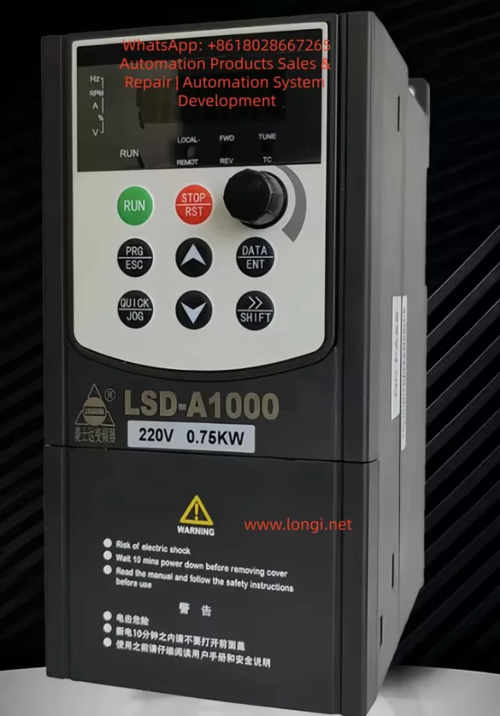
The Lingshida LSD-A1000 series inverter control panel integrates a display screen and multiple functional buttons, facilitating parameter settings, status monitoring, and fault troubleshooting. The panel layout is as follows:
| Button/Indicator | Function Description |
|---|---|
| RUN (Run) | Starts the inverter operation |
| STOP/RST (Stop/Reset) | Stops operation or resets faults |
| PRG/ESC (Program/Exit) | Enters or exits parameter setting mode |
| DATA/ENT (Data/Enter) | Confirms parameter settings or enters the next menu level |
| △ (Increase) | Increases parameter values or selects the previous item |
| ▽ (Decrease) | Decreases parameter values or selects the next item |
| →/SHIFT (Shift) | Switches display parameters or selects the modification position |
| QUICK/JOG (Quick/Jog) | Quick function switching or jog operation |
| Potentiometer Knob | Adjusts output frequency or other analog parameters |
| LED Indicators | Displays operating status, fault status, frequency, current, voltage, etc. |
LED Indicator Descriptions:
- RUN (Red): Inverter is running.
- FWD/REV (Red): Motor is in forward/reverse operation.
- LOCAL/REMOT (Red): Local/remote control mode.
- TC (Red): Torque control mode or fault status (flashing indicates a fault).
1.2 How to Restore Factory Default Settings
The Lingshida LSD-A1000 series inverter supports restoring all parameters to factory default values. Follow these steps:
- Enter Parameter Setting Mode:
- Press the PRG/ESC key to enter the function code editing state.
- Use the △/▽ keys to select FA-11 (Product Number) or FA-12 (Software Version Number) to confirm the current version.
- Restore Factory Settings:
- In the stopped state, press and hold the PRG/ESC key for more than 5 seconds until the display shows the “rES” prompt.
- Press the DATA/ENT key to confirm the restoration of factory settings.
- The inverter will restart, and all parameters will be reset to default values.
Note:
- Restoring factory settings will clear all user-defined parameters, including passwords and PID parameters.
- After restoration, you need to reconfigure motor parameters (such as rated current and rated frequency).
1.3 How to Set and Remove Passwords
To prevent unauthorized parameter modifications, the Lingshida LSD-A1000 supports password protection.
Setting a Password:
- Enter FA-00 (User Password Setting):
- Press PRG/ESC → Select the FA group → Select FA-00.
- Enter a 5-digit password (default is 00000).
- Press DATA/ENT to confirm.
- Enable Password Protection:
- Enter FA-01 (Password Protection Enable):
- 0: Disable password protection.
- 1: Enable password protection.
- Enter FA-01 (Password Protection Enable):
Removing a Password:
- Enter the Correct Password:
- When entering parameter settings, the system prompts for a password.
- Enter the correct password and press DATA/ENT to confirm.
- Reset Password if Forgotten:
- Press and hold the PRG/ESC key for 5 seconds to restore factory settings (password resets to 00000).
Note:
- After setting a password, modifying critical parameters (such as F3 group motor parameters) requires entering the password.
- The manufacturer’s password (for advanced parameters) cannot be cleared by restoring factory settings; contact the manufacturer.
1.4 How to Set Parameter Access Restrictions
To prevent accidental modifications, you can restrict access to certain parameters:
- Set Parameter Modification Permissions:
- The “Change” column in the function code table indicates modification permissions:
- ★: Can be modified during both operation and stop.
- ☆: Can only be modified when stopped.
- ●: Read-only, cannot be modified (such as fault records).
- The “Change” column in the function code table indicates modification permissions:
- Lock Critical Parameters:
- After setting a password in FA-00 (User Password), parameters in F3 group (Motor Parameters) and FC group (PID Parameters) cannot be modified without the password.
- Lock Buttons:
- Set via FA-00 (QUICK/JOG Key Function):
- 0: QUICK/JOG key is disabled.
- 1: Switch between local and remote control.
- 2-4: Jog function (to prevent accidental operation).
- Set via FA-00 (QUICK/JOG Key Function):
2. Terminal Forward/Reverse Control and External Potentiometer Frequency Adjustment
2.1 Parameter Settings and Wiring for Terminal Forward/Reverse Control
The Lingshida LSD-A1000 supports forward/reverse control through DI (Digital Input) terminals.
Parameter Settings:
| Function Code | Setting Value | Description |
|---|---|---|
| F6-00 (DI1 Function Selection) | 1 (Forward Run) | DI1 connected for forward operation |
| F6-01 (DI2 Function Selection) | 2 (Reverse Run) | DI2 connected for reverse operation |
| F6-11 (Terminal Command Mode) | 0 (Two-Wire Mode 1) | DI1/DI2 control forward/reverse separately |
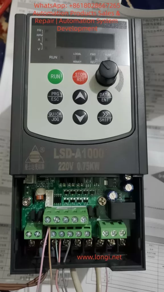
Wiring Steps:
- Connect DI1 (Forward) and DI2 (Reverse):
- Connect DI1 to the forward button or PLC output.
- Connect DI2 to the reverse button or PLC output.
- Connect COM to 24V- (common ground).
- Set Command Source:
- F0-21 (Command Source Selection) = 1 (Terminal Command Channel).
- Start Testing:
- Connect DI1, and the motor runs forward.
- Connect DI2, and the motor runs in reverse.
Note:
- Ensure F1-06 (Stop Mode) = 0 (Deceleration Stop) to avoid sudden stops.
- For three-wire control (forward/reverse/stop), set F6-11 = 2 (Three-Wire Mode 1).
2.2 Parameter Settings and Wiring for External Potentiometer Frequency Adjustment
Frequency adjustment can be achieved through AI1 (Analog Input) using an external potentiometer.
Parameter Settings:
| Function Code | Setting Value | Description |
|---|---|---|
| F0-02 (Main Frequency Source Selection) | 2 (AI1) | Frequency given by AI1 |
| F6-13 (AI Curve Minimum Input) | 0.00V | Potentiometer minimum voltage corresponds to 0Hz |
| F6-16 (AI Curve Maximum Input) | 10.00V | Potentiometer maximum voltage corresponds to 50Hz |
| J13 (AI1 Input Mode) | 1-2 (0-10V) | Voltage input mode |
Wiring Steps:
- Connect the Potentiometer:
- Connect the middle pin of the potentiometer to AI1.
- Connect one end of the potentiometer to +10V (provided by the inverter).
- Connect the other end of the potentiometer to COM.
- Set Frequency Range:
- F0-09 (Maximum Frequency) = 50.00Hz.
- F0-12 (Minimum Frequency) = 0.00Hz.
- Start Testing:
- Rotate the potentiometer, and the output frequency changes with the voltage.
Note:
- The potentiometer resistance is recommended to be 5K-10KΩ.
- For current input (4-20mA), short J13 to 2-3.
3. Inverter Fault Codes and Solutions
3.1 Common Fault Code List
| Fault Code | Fault Description | Possible Causes |
|---|---|---|
| E01 | Wave-by-Wave Current Limiting Fault | High starting current, heavy load |
| E02 | Acceleration Overcurrent | Short acceleration time, motor locked |
| E03 | Deceleration Overcurrent | Short deceleration time, braking resistor failure |
| E04 | Constant Speed Overcurrent | Sudden load change, motor overload |
| E05 | Acceleration Overvoltage | High input voltage, braking unit failure |
| E06 | Deceleration Overvoltage | Short deceleration time, braking resistor damage |
| E11 | Motor Overload | Motor overheating, poor cooling |
| E12 | Input Phase Loss | Loose power line, blown fuse |
| E13 | Output Phase Loss | Motor line break, contactor failure |
| E15 | External Fault | External emergency stop signal triggered |
| E16 | Communication Fault | MODBUS communication interruption |
| E23 | Running Time Reached | Timer setting triggered stop |
| E24 | User-Defined Fault 1 | DI terminal triggered custom fault |
3.2 Fault Cause Analysis and Solutions
E02 (Acceleration Overcurrent)
- Cause: Acceleration time is too short, or the load inertia is too large.
- Solution:
- Increase F0-13 (Acceleration Time 1).
- Check if the motor is locked.
E05 (Acceleration Overvoltage)
- Cause: Input voltage is too high, or the braking unit is not enabled.
- Solution:
- Check if the input voltage is within 380V±10%.
- Enable F1-14 (Energy Consumption Braking Point) and connect a braking resistor.
E11 (Motor Overload)
- Cause: Motor overheating, cooling fan failure.
- Solution:
- Check if the motor cooling is normal.
- Adjust F8-01 (Motor Overload Protection Gain).
E12 (Input Phase Loss)
- Cause: Loose power line, blown fuse.
- Solution:
- Check if the R/S/T terminals are properly connected.
- Replace the fuse.
E16 (Communication Fault)
- Cause: MODBUS line disconnection, address conflict.
- Solution:
- Check the RS485 line connection.
- Ensure P0-01 (Communication Address) is unique.
4. Summary and Precautions
- Control Panel: Familiarize yourself with button functions and set passwords and parameter restrictions reasonably.
- Terminal Control: Correctly wire DI/AI terminals to avoid misoperation.
- Fault Troubleshooting: Check power supply, load, and parameter settings one by one according to fault codes.
- Safety Precautions:
- Wait 10 minutes after power-off before maintenance.
- Avoid using in high-temperature or humid environments.
Conclusion The Lingshida LSD-A1000 series inverter is powerful but requires strict operation according to the manual. This guide helps users quickly master basic operations, parameter settings, and fault troubleshooting methods to ensure stable equipment operation. For complex issues, contact the manufacturer’s technical support.