
1. Introduction: Why Does SINAMICS V20 Display F11 Fault? In industrial automation systems, Siemens SINAMICS V20 frequency converters are widely used in applications such as fans, pumps, conveyors, packaging machines, machine tools, and general-purpose drive systems. Due to their compact design, simple commissioning process, and reliable performance, V20 drives have become one of the most popular variable frequency drives for…
Year: 2026
WDI ATF5 Laser Displacement Sensor Troubleshooting and Repair Guide: A Systematic Approach from Laser Failure to Measurement Recovery
Introduction In modern industrial automation systems, laser displacement sensors have become essential measurement devices due to their high accuracy, fast response speed, and non-contact measurement capability. They are widely used in precision manufacturing, mechanical positioning, dimensional inspection, thickness measurement, robotic applications, and automated quality control systems. Among industrial laser sensors, the WDI (WDI Device, Canada) ATF5 series laser displacement sensors…
Mitsubishi FR-F840 E.UVT Undervoltage Fault Troubleshooting Guide: A Complete Diagnostic Approach from DC Bus Charging to Voltage Detection Circuit Failure
Introduction In industrial automation systems, variable frequency drives (VFDs) are widely used for controlling motors in applications such as pumps, fans, compressors, conveyors, machine tools, and production equipment. As the operating environment becomes more demanding, VFDs are exposed to voltage fluctuations, temperature stress, dust contamination, and long-term electrical aging. When a drive displays a fault code, many technicians immediately associate…
Siemens SINAMICS S120 F30025 and F00004 Fault Analysis: Why an Instant Overtemperature Alarm on a Cold Drive Usually Indicates a Motor Module Problem
Introduction The Siemens SINAMICS S120 drive system is widely used in high-performance industrial applications such as CNC machine tools, robotics, packaging systems, printing equipment, metallurgy production lines, and complex automation platforms. Compared with standard frequency converters, the SINAMICS S120 adopts a highly modular architecture, providing excellent flexibility and performance. However, the advanced structure of the S120 also makes troubleshooting more…
ABB Soft Starter Power Supply Board Failure Diagnosis and Repair Analysis: A Technical Study Based on the 1SFB536268D1007 Power Board
Abstract ABB soft starters are widely used in industrial motor control systems for applications requiring reduced starting current, smooth acceleration, controlled stopping, and motor protection. As one of the most important internal components, the power supply board plays a critical role in converting incoming AC power into multiple stable DC voltages required by the control system, trigger circuits, communication modules,…
Deep Analysis of SINAMICS S120 F30005 and F30021 Faults After IGBT Replacement: How a -78A W-Phase Current Offset Reveals a Current Feedback Circuit Failure
Abstract Siemens SINAMICS S120 drive systems are widely used in high-performance industrial applications, including CNC machines, robotics, printing equipment, semiconductor manufacturing, packaging systems, and other precision automation fields. Due to their advanced modular power structure, SINAMICS S120 power units have very strict requirements for power semiconductors, current measurement circuits, gate drive circuits, and protection feedback systems. During field maintenance, one…
Systematic Diagnosis of High-Temperature Shutdowns and Power-Version Read Failures in Antminer S19 XP Hyd. and S19 XP+ Hyd. Miners
Introduction In large-scale hydro-cooled mining facilities, Antminer S19 XP Hyd. and S19 XP+ Hyd. miners are commonly installed in groups and operated through centralized power distribution and cooling systems. Compared with conventional air-cooled miners, hydro-cooled models eliminate high-speed cooling fans and instead rely on circulating coolant, internal cold plates, pumps, heat exchangers, manifolds, and external cooling equipment to remove heat…
Diagnostic Methods for Huazhong CNC HNC-210B Spindle Failure, Low-Speed Crawling After Stop, and “Output Shows Low but Relay Remains Energized” — A Practical Analysis Based on PLC/PMC I/O Mapping, Emergency Stop Logic, and the XS91 Spindle Interface
1. Fault Background and Core Problem The Huazhong CNC HNC-210B is an older integrated CNC control system commonly used on grinders, lathes, special-purpose machines, and retrofit equipment. It combines CNC control, PMC/PLC logic, operator panel keys, machine I/O, spindle interface, feed-axis interface, and related machine control functions in one unit. In real maintenance work, this type of system often produces…
GSK DAD08A Dual-Axis Servo Drive Manual Guide: Dual-Axis Wiring, Single-Axis JOG, Electronic Gear, Parameter Backup, Alarm Isolation and Repair
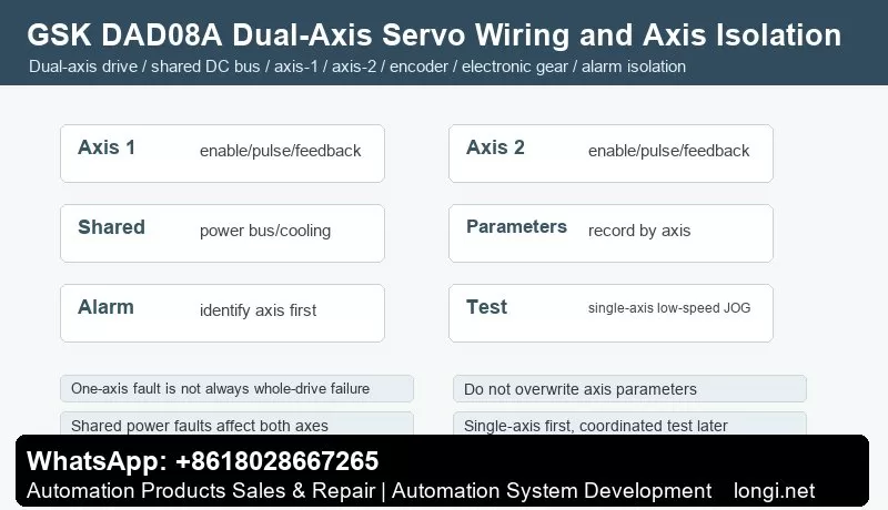
GSK DAD08A Dual-Axis Servo Drive Manual Guide: Dual-Axis Wiring, Single-Axis JOG, Electronic Gear, Parameter Backup, Alarm Isolation and Repair DAD08A Service Focus GSK DAD08A is a dual-axis servo drive used on CNC machines, feeding units and compact automation systems. Unlike single-axis DA98 drives, one drive manages two servo motors. The axes may share power bus, cooling and protection, but command…
Daikin Super Unit Manual Guide: Installation, Hydraulic Piping, Electrical Wiring, Filter, Regenerative Resistor, Pressure Sensor, Pump Replacement and Maintenance Diagnosis
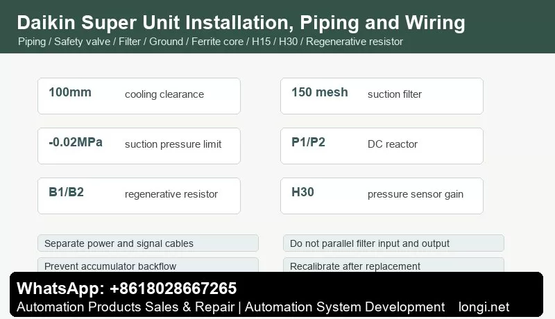
Daikin Super Unit Manual Guide: Installation, Hydraulic Piping, Electrical Wiring, Filter, Regenerative Resistor, Pressure Sensor, Pump Replacement and Maintenance Diagnosis Why Installation and Maintenance Matter Many Daikin Super Unit faults do not come from the controller board itself. Common causes include poor cooling space, bad suction piping, weak grounding, incorrect filter wiring, pressure sensor cable vibration, hot regenerative resistor and…