In industrial field service, repairing a Siemens drive is rarely a matter of simply replacing a faulty board and powering the unit back on. This is especially true for the SINAMICS S120 platform, which is a highly modular drive system. In S120 architecture, the Control Unit, Power Module, EEPROM identity data, drive objects, motor data, encoder configuration, and communication structure are all tightly interlinked. A repair that resolves one layer of the system may expose issues in another.
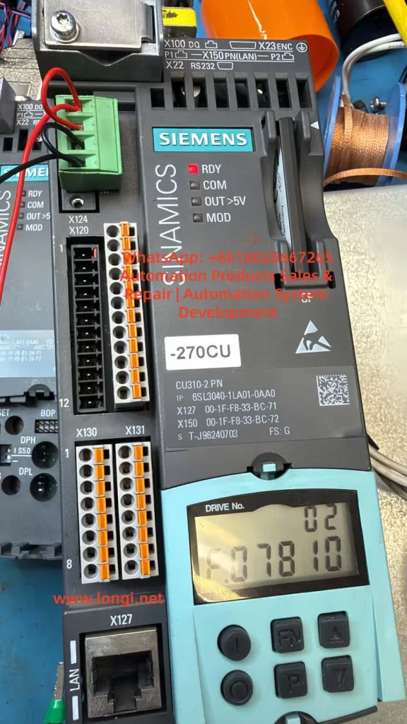
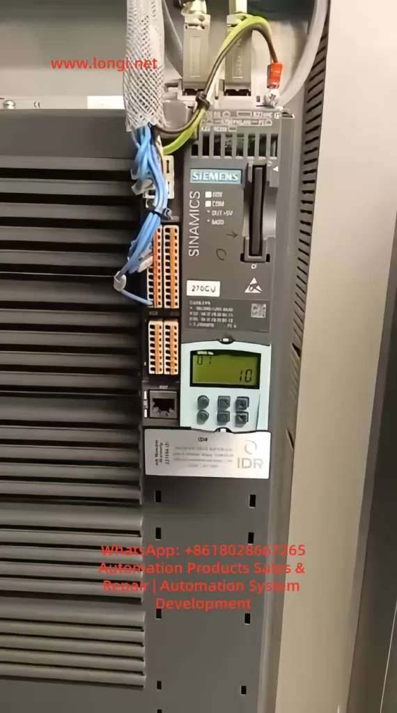
A common and often misunderstood scenario occurs when a drive initially reports fault F01112. After replacing the power PCB or rewriting the EEPROM data, the fault disappears, the drive powers up normally, and no errors are displayed. However, a new symptom appears: the RDY (Ready) LED flashes slowly, while the COM LED remains solid green. At the same time, an identical drive installed nearby shows both RDY and COM LEDs solid green.
At this point, many engineers mistakenly assume the EEPROM data is still incorrect or that the replacement board is incompatible. In reality, this situation usually indicates that the problem has moved from a hardware identity mismatch to a commissioning state issue. The drive now recognizes the hardware, but the system has not yet completed or exited its commissioning phase.
This article provides a structured analysis of this condition, explaining the transition from EEPROM-related faults to commissioning mode behavior, and outlines a practical method to restore the drive to full Ready status.
1. Understanding the Original Fault: F01112
The fault code F01112 is often loosely interpreted as an EEPROM failure or a defective power board. However, this is not technically precise. The real meaning of F01112 is:
The Control Unit does not accept the connected Power Module due to an identity or compatibility mismatch.
In the SINAMICS S120 system, the Control Unit (such as CU310-2 PN) performs an identity verification during startup. It reads electronic nameplate data stored in the EEPROM of the power section. This data includes not only identification but also system classification, version compatibility, and configuration attributes.
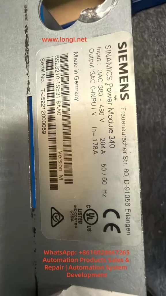
If the EEPROM contains data belonging to a different system—such as G120 instead of S120—the Control Unit will reject the module and issue F01112. Importantly, this rejection occurs even if the hardware itself is electrically sound.
2. Why S120 and G120 Cannot Be Interchanged
At a hardware level, some G120 and S120 components may appear physically compatible. However, their system architectures are fundamentally different.
G120 is typically a more integrated system with predefined relationships between control and power components.
S120 is modular, with flexible combinations of Control Units, Power Modules, Motor Modules, and communication interfaces.
The CU310-2 PN is designed specifically for S120 architecture and expects a compatible Power Module with corresponding identity data. A board carrying G120 identity data may function electrically, but will not be accepted logically within an S120 system.
3. What It Means When F01112 Disappears
When F01112 is successfully cleared after rewriting EEPROM data, this indicates that:
The Control Unit now accepts the identity of the Power Module.
This is a critical milestone. It confirms that the system has passed the hardware identity verification stage. Any remaining issues are no longer related to hardware compatibility, but rather to system configuration and operational state.
At this point, continuing to suspect EEPROM data is usually a misdirection. The focus must shift to the commissioning and parameter layers.
4. Interpreting the LED Status
The LED indicators provide useful but limited diagnostic information.
COM LED (Solid Green)
A solid green COM LED indicates that communication is active. This suggests that fieldbus or internal communication (such as DRIVE-CLiQ) is functioning correctly.
RDY LED (Slow Flashing Green)
A slowly flashing RDY LED, combined with no fault messages, typically indicates that:
The drive is not in a fault condition
The system is not yet fully ready for operation
The drive is likely in a commissioning or pre-ready state
This is consistent with a system that has not completed initial setup or has not exited commissioning mode.
5. Why Commissioning Mode Appears After EEPROM Replacement
Rewriting the EEPROM resolves identity-related issues, but does not restore all system parameters. The S120 system requires a complete set of configuration data, including:
Drive object definitions
Motor data sets (MDS)
Encoder data sets (EDS)
Control modes
Parameter interconnections (BICO)
Communication mappings
If any of these are incomplete or inconsistent, the drive may automatically enter a commissioning state.
In effect:
The system recognizes the hardware but cannot confirm that it is fully configured for operation.
This leads to the observed behavior: no fault, but not fully Ready.
6. Distinguishing Hardware Issues from Commissioning State
A key skill in troubleshooting is distinguishing between these two categories.
Hardware Identity Issue
Fault codes present (e.g., F01112)
System refuses to initialize
No progression beyond startup checks
Commissioning State Issue
No active fault codes
Communication operational
RDY LED flashing
System not enabling drive operation
Recognizing this distinction prevents unnecessary hardware interventions and focuses troubleshooting on parameter verification.
7. Critical Parameters to Check
LED indicators alone are insufficient for diagnosis. The following parameters must be checked:
r0002 – Drive State
This parameter indicates the current system status.
Typical relevant values:
Indicates initial commissioning required
Indicates commissioning mode not exited
p0009 – Control Unit Commissioning State
p0010 – Drive Object Commissioning State
p3900 – Commissioning Completion Trigger
In a fully operational system:
p0009 = 0
p0010 = 0
If p0010 is non-zero, the drive is still in commissioning mode.
To exit commissioning:
Complete required parameter entries
Execute commissioning completion (e.g., p3900)
Save parameters and reboot
8. Using a Working Drive as Reference
In this case, the presence of an identical, fully operational drive is extremely valuable.
The most effective approach is:
Read key parameters from the working drive
Compare them with the repaired unit
Identify differences in:
Drive object configuration
Motor and encoder data
Commissioning parameters
Communication setup
This direct comparison eliminates guesswork and provides a reliable path to resolution.
9. Recommended Troubleshooting Procedure
Confirm that F01112 is fully cleared
Observe LED states (RDY flashing, COM solid)
Read r0002 to determine system state
Check p0009 and p0010 for commissioning status
If necessary, complete commissioning process
Execute commissioning completion via p3900
Save parameters to non-volatile memory
Power cycle the drive
Compare with a known-good system if available
10. Common Pitfalls
Many repair attempts fail at this stage due to:
Continuing to suspect EEPROM after it is already correct
Ignoring parameter-level diagnostics
Relying solely on LED indicators
Not saving parameters after modification
Skipping commissioning completion steps
Understanding that the problem has shifted from hardware to system configuration is essential.
11. Key Takeaways for Engineers
This case highlights three important principles:
1. Hardware and System Layers Are Interdependent
Fixing hardware identity does not guarantee operational readiness.
2. Faults Evolve Through Stages
The problem moved from identity mismatch to commissioning state.
3. Parameter Analysis Is Critical
Final system readiness depends on correct parameter configuration.
12. Final Conclusion
When a SINAMICS S120 drive clears F01112 after EEPROM correction but shows a flashing RDY LED, the issue is no longer hardware-related. Instead, it indicates that the system has not completed or exited commissioning mode.
The correct approach is to verify system state parameters, complete any required commissioning steps, and ensure all parameters are saved properly.
Only when the drive exits commissioning mode and reaches a stable state will the RDY LED become solid green, matching the behavior of a fully operational unit.
In advanced drive systems like S120, successful repair requires not only restoring hardware functionality but also ensuring full system-level readiness.
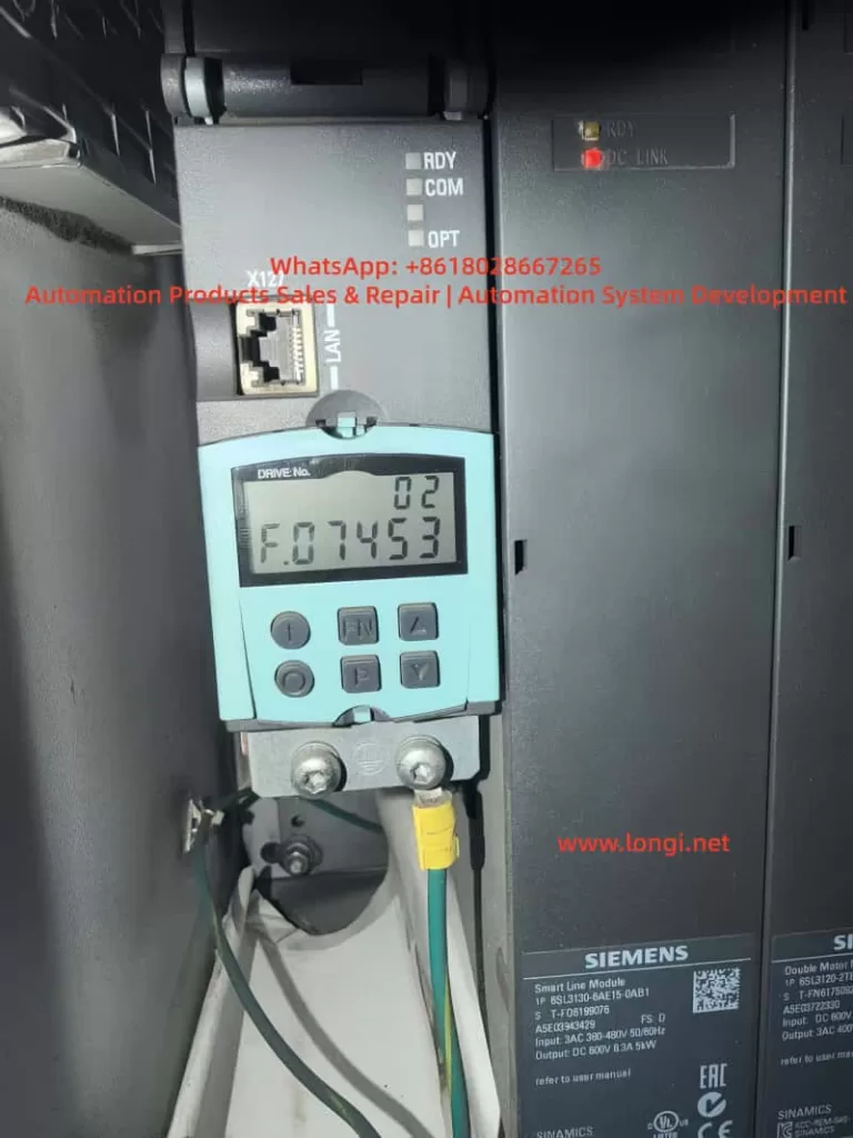
In Siemens SINAMICS S120 drive systems, F07453 is a position feedback-related fault. Its typical meaning is:
LR: Position actual value preprocessing error
In practical terms, this means the drive cannot correctly process the actual position feedback required by the position control loop.
This fault is not normally related to a DC bus power failure, rectifier fault, motor overload, or main power module short circuit. It is mainly associated with the encoder feedback chain, position actual value processing, and position loop encoder assignment.
SINAMICS S120 is a modular high-performance multi-axis drive system. A typical system may include a Smart Line Module, Active Line Module, Motor Module, Control Unit, Sensor Module, DRIVE-CLiQ communication network, motor encoder, external measuring system, and BOP20 operator panel. Because of this modular architecture, fault F07453 must be analyzed systematically instead of simply judging the drive as defective.
The key point of F07453 is:
The drive cannot obtain or process a valid actual position value for the position control loop.
2. Technical Meaning of F07453
In a servo drive system, the position loop normally depends on three basic values:
Position setpoint This is the target position from the PLC, CNC, motion controller, or internal positioning function.
Position actual value This is the real mechanical position feedback from the motor encoder, external encoder, linear scale, rotary encoder, or other measuring system.
Position deviation This is the difference between the position setpoint and the position actual value.
For SINAMICS S120, the encoder signal cannot always be used directly. The drive must first process the feedback signal. This preprocessing may include:
Detecting whether the encoder exists;
Identifying the encoder type;
Checking encoder communication;
Checking encoder supply voltage and signal validity;
Reading encoder resolution;
Processing incremental or absolute position data;
Checking the zero pulse or reference mark;
Checking encoder direction;
Converting encoder data into mechanical position;
Calculating electrical angle when required;
Processing multiturn absolute encoder data;
Checking the encoder data set;
Confirming which encoder is assigned to the position loop;
Converting the feedback into an internal actual position value.
This process is called position actual value preprocessing.
Therefore, F07453 does not simply mean “the encoder is bad”. Its more accurate meaning is:
The drive failed while converting the encoder or measuring system feedback into a valid actual position value for the position control loop.
This failure may be caused by hardware, wiring, parameter configuration, DRIVE-CLiQ topology, encoder assignment, data set mismatch, or mechanical feedback problems.
3. Why F07453 Should Not Be First Treated as a Power Module Fault
A SINAMICS S120 booksize system is usually composed of several modules:
Module
Main Function
Smart Line Module / Active Line Module
Converts three-phase AC input into DC link voltage
Motor Module
Converts DC link voltage into three-phase motor output
Control Unit
Handles axis control, communication, parameters, and system logic
Sensor Module
Processes external encoder or measuring system signals
DRIVE-CLiQ
Internal high-speed communication link
BOP20
Local operation and fault display panel
If the Smart Line Module or Active Line Module is faulty, the fault usually relates to input power, rectification, pre-charging, DC bus voltage, regenerative operation, temperature, or input phase loss.
If the Motor Module power section is faulty, the fault usually relates to overcurrent, ground fault, short circuit, IGBT failure, output phase loss, or motor insulation failure.
However, F07453 belongs to the position feedback and position actual value processing category. The main focus is not the power circuit, but whether the drive can receive and process valid feedback for the position loop.
Therefore, when troubleshooting F07453, the first priority should be:
Encoder;
Encoder cable;
Encoder connector;
Sensor Module;
DRIVE-CLiQ communication;
Encoder parameters;
Position loop encoder assignment;
Motor and encoder data sets;
Drive Object configuration;
Mechanical feedback system.
The Smart Line Module or main power section should only be considered after the feedback chain and parameter configuration have been checked.
4. Common Causes of F07453
4.1 Encoder Failure
The encoder is the source of the actual position value. If the encoder fails, the drive may not receive valid position feedback and may trigger F07453.
Common encoder-related problems include:
Internal encoder circuit failure;
Encoder power supply short circuit;
Contaminated optical encoder disc;
Damaged magnetic encoder ring;
Abnormal multiturn absolute encoder data;
EnDat, SSI, or DRIVE-CLiQ encoder communication failure;
Weak A/B/Z incremental signals;
Distorted Sin/Cos signals;
Damaged encoder memory data;
Moisture, oil, or dust inside the encoder;
Poor contact inside the encoder connector.
If the drive reports F07453 immediately after power-on or immediately after enable, the encoder should be checked first. When the motor shaft is turned manually, the actual position value should change continuously in the engineering software. If the value does not change, jumps randomly, changes in the wrong direction, or becomes invalid, the encoder or feedback chain is highly suspicious.
4.2 Encoder Cable, Connector, or Shielding Problem
The encoder cable is one of the most common causes of F07453. Encoder signals are weak signals, especially Sin/Cos, TTL, HTL, SSI, and EnDat signals. They are sensitive to cable quality, shielding, grounding, and connector reliability.
Typical cable and connector problems include:
Loose encoder connector;
Bent, oxidized, or retracted connector pins;
Oil or moisture inside the connector;
Broken wire inside a drag chain cable;
Damaged shield layer;
Poor shield grounding;
Encoder cable bundled together with motor power cable;
Encoder cable routed near contactors, braking resistors, or other high-interference sources;
Incorrect wiring in a custom-made encoder cable;
Cable length exceeding the recommended limit;
Cable mechanically crushed or stretched.
If F07453 occurs only at a certain machine position or randomly during movement, a broken wire inside the drag chain should be suspected. Static continuity measurement with a multimeter may not reveal the problem. The cable may appear normal when stationary but fail during movement.
In this case, replacing the encoder cable with a known good cable is often more effective than simple continuity testing.
4.3 Encoder Power Supply Problem
Different encoders require different supply voltages, such as 5 V, 10 V, 24 V, or 10–30 V. If the encoder supply is unstable or incorrect, the encoder cannot output valid feedback signals.
Typical problems include:
No encoder supply voltage;
Low encoder supply voltage;
Excessive ripple on the encoder supply;
Insufficient current capacity;
Poor contact in the supply wires;
Internal encoder short circuit pulling down the supply;
Abnormal 0 V reference;
Incorrect shorting between shield and signal ground;
Damaged encoder supply output from the Sensor Module.
The encoder supply should be measured with the encoder connected, not only under no-load conditions. A no-load voltage may appear normal, but the voltage may drop significantly when the encoder is connected and operating.
4.4 Sensor Module Failure or Incorrect Configuration
In many S120 systems, encoder feedback is connected through SMC or SME Sensor Modules rather than directly through the motor. If the Sensor Module fails or is incorrectly configured, F07453 may occur.
Possible Sensor Module-related causes include:
Faulty SMC20, SMC30, or other Sensor Module;
Abnormal module power supply;
Communication problem between Sensor Module and Control Unit;
Poor connector contact;
Encoder type incompatible with the Sensor Module;
Changed DRIVE-CLiQ topology;
Module replaced but not re-identified;
Actual module type different from the configured module type;
Wrong encoder data set assignment.
If several identical Sensor Modules are available on the machine, cross-swapping can be used to determine whether the fault follows the module.
4.5 DRIVE-CLiQ Communication or Topology Problem
DRIVE-CLiQ is the internal communication system used by SINAMICS S120 to connect the Control Unit, Motor Modules, Sensor Modules, and DRIVE-CLiQ motors. Although F07453 is not purely a communication fault, DRIVE-CLiQ problems can prevent encoder data from being correctly identified or used.
Typical DRIVE-CLiQ-related causes include:
Loose DRIVE-CLiQ cable;
Damaged DRIVE-CLiQ cable;
Changed topology sequence;
Topology mismatch after module replacement;
Dirty or oxidized DRIVE-CLiQ connector;
Incorrect cable used instead of a suitable DRIVE-CLiQ cable;
Actual wiring different from the project topology;
Control Unit unable to identify a node correctly.
The S120 system is sensitive to topology. After replacing modules or reconnecting cables, the actual DRIVE-CLiQ topology must match the project configuration.
4.6 Incorrect Position Loop Encoder Assignment
F07453 is closely related to encoder assignment in the position loop. In a S120 axis, the position feedback source may be:
Motor encoder;
Second encoder;
Load-side encoder;
Linear scale;
Rotary encoder;
Direct measuring system;
Virtual encoder;
Actual position value from a higher-level controller.
The position loop must know exactly which feedback source to use. If the position loop is assigned to a non-existing, inactive, invalid, or incorrectly configured encoder, F07453 may occur.
Typical examples include:
The machine only has a motor encoder, but the position loop is assigned to encoder 2;
The system uses a load-side scale, but the project still points to the motor encoder;
The encoder data set was not created after motor replacement;
A Drive Data Set refers to the wrong Encoder Data Set;
Parameters copied from another axis created encoder assignment mismatch;
Project download cleared or changed the position feedback source.
In this situation, the hardware may be completely normal, but the drive still cannot use the actual position value because the assignment is wrong.
4.7 Motor, Encoder, and Drive Parameter Mismatch
SINAMICS S120 is a highly parameterized servo system. Motor data, encoder data, power module data, mechanical transmission ratio, control mode, and topology must match each other.
Common mismatch cases include:
Motor replaced with a different model;
Encoder replaced with a different type;
Substitute motor used without parameter update;
Motor nameplate data not matching the project;
Encoder pulse number set incorrectly;
Absolute encoder bit number set incorrectly;
Sin/Cos interpolation setting incorrect;
Motor pole pair number incorrect;
Mechanical transmission ratio incorrect;
Encoder direction incorrect;
Motor Data Set and Encoder Data Set not matching;
Drive Object parameters copied from another machine.
This type of problem is common after maintenance, especially when used spare parts, repaired modules, replacement motors, or copied CF card data are involved. Two motors may look physically similar but have completely different encoder systems.
4.8 Mechanical Feedback System Problem
Although F07453 mainly points to feedback signal processing or parameter assignment, mechanical problems can also cause abnormal actual position feedback, especially when a load-side encoder or linear scale is used.
Possible mechanical causes include:
Loose encoder coupling;
Broken encoder shaft;
Slipping belt;
Excessive gearbox backlash;
Contaminated linear scale head;
Loose scale installation;
Load encoder direction opposite to motor encoder direction;
Mechanical axis jammed;
Reference switch problem;
Lost machine zero point;
External measuring system shifted from its original position.
If the system uses dual encoders, such as a motor encoder for the speed loop and a load-side encoder for the position loop, checking only the motor encoder is not enough. The actual feedback source used by the position loop must be confirmed.
5. Systematic Troubleshooting Procedure
5.1 Identify the Faulty Drive Object
S120 is a multi-axis system. One Control Unit may manage several Drive Objects. When BOP20 displays F07453, the first step is to identify which Drive Object is reporting the fault.
The following information should be confirmed:
Drive No.;
Drive Object name;
Related Motor Module channel;
Related motor;
Related encoder;
Related Sensor Module;
Whether the axis uses position control;
Whether EPOS is used;
Whether a second encoder or external measuring system is used.
Without identifying the correct axis, troubleshooting may focus on the wrong motor or module.
5.2 Read Fault Records and Fault Values
Fault records should be read through BOP20, STARTER, or Startdrive.
Important information includes:
Current fault code;
Fault value;
Fault time;
Faulty Drive Object;
Associated alarms or faults;
Whether the fault occurs at power-on, enable, running, homing, or positioning;
Whether the fault can be reset;
Whether it returns immediately after reset.
If F07453 appears together with encoder, DRIVE-CLiQ, encoder supply, or encoder data set alarms, those associated messages should guide the next step.
5.3 Check Encoder Connector and Cable
This is the most practical field inspection step.
Recommended checks:
Power off and reconnect the encoder connector;
Check the connector locking mechanism;
Inspect pins for bending, oxidation, or retraction;
Check the cable jacket for damage;
Inspect drag chain sections;
Check whether the cable is crushed or stretched;
Confirm proper shield connection;
Separate encoder cable from motor power cable;
Check cabinet grounding;
Replace with a known good encoder cable for testing.
Encoder cable problems should not be judged only by static continuity measurement. Signal quality, shielding, dynamic bending, and high-frequency integrity are equally important.
5.4 Check Encoder Supply and Signal
For traditional encoders such as incremental, Sin/Cos, SSI, or EnDat, encoder supply and signal quality should be checked.
Supply checks:
Correct supply voltage;
No voltage drop under load;
Low ripple;
Reliable 0 V reference;
No short to ground;
Sensor Module encoder supply output normal.
Signal checks:
A/B signals present;
Z pulse or reference mark present if required;
Sin/Cos amplitude normal;
SSI / EnDat communication stable;
Signal changes continuously when shaft rotates;
No spikes, missing pulses, or amplitude collapse;
Shielding effective.
If an oscilloscope is used, grounding must be handled carefully to avoid creating a short circuit or introducing interference.
5.5 Monitor the Actual Position Value Online
Using STARTER or Startdrive to monitor the actual position value is one of the most important diagnostic methods.
When the motor shaft is manually turned under safe conditions, the actual position value should:
Change continuously;
Change in the correct direction;
Not jump randomly;
Not become invalid;
Not disappear intermittently;
Show normal encoder status;
Show normal topology status.
Abnormal symptoms include:
Position value does not change;
Position value jumps randomly;
Direction is reversed;
Value suddenly resets;
Value becomes invalid;
Encoder cannot be detected;
Encoder status appears and disappears;
Fault occurs immediately when the shaft is turned.
These observations can help distinguish between encoder, cable, Sensor Module, and parameter problems.
5.6 Check Position Loop Encoder Assignment
If the encoder appears online but F07453 remains, the position loop encoder assignment must be checked.
Key points:
Whether position control is enabled;
Which feedback source is assigned to the position loop;
Whether the assigned encoder actually exists;
Whether a second encoder is configured;
Whether an external measuring system is used;
Whether the Encoder Data Set is valid;
Whether Drive Data Set switching changes encoder reference;
Whether copied parameters created encoder number mismatch;
Whether topology changes were updated in the project.
If the position loop is assigned to the wrong encoder, the encoder may appear healthy, but the position control loop still cannot use the actual value.
5.7 Check Motor and Encoder Data Sets
If the motor, encoder, Motor Module, Control Unit, CF card, or project has been replaced or modified, the data sets must be verified carefully.
Important checks include:
Item
Possible Problem
Motor model
Control model does not match actual motor
Encoder type
Feedback cannot be processed correctly
Encoder resolution
Position value conversion error
Encoder direction
Position loop instability or error
Mechanical ratio
Incorrect actual position scaling
Motor pole pair number
Incorrect electrical angle calculation
Encoder Data Set
Invalid or wrong data set
Drive Data Set
Wrong feedback source after switching
Topology
Actual hardware does not match project
A module that powers up normally is not necessarily correctly configured. In S120 systems, hardware and parameters must match exactly.
5.8 Perform Cross-Swapping Tests
If identical axes or spare modules are available, cross-swapping is an efficient way to identify the fault source.
Recommended sequence:
Swap encoder cables;
Swap DRIVE-CLiQ cables;
Swap Sensor Modules;
Swap motor encoder or complete motor;
Swap Motor Module channel;
Consider Control Unit or CF card only at the final stage.
Judgment table:
Swapped Part
If the Fault Follows
Likely Cause
Encoder cable
Yes
Cable problem
Motor / encoder
Yes
Encoder or motor feedback problem
Sensor Module
Yes
Sensor Module problem
Motor Module channel
Yes
Motor Module interface or channel problem
Parameter / CF card
Yes
Parameter or project problem
Same mechanical axis
Yes
Mechanical side or field wiring problem
Parameters must be backed up before cross-swapping. Randomly exchanging Control Units, CF cards, or project files may create new topology or safety configuration problems.
6. Troubleshooting by Fault Scenario
6.1 Machine Was Working Normally, Then Suddenly Reports F07453
In this case, hardware and connection issues are more likely.
Priority checks:
Encoder cable damage;
Loose encoder connector;
Encoder failure;
Sensor Module failure;
DRIVE-CLiQ cable problem;
Shielding or grounding issue;
Increased field interference.
Recommended actions:
Check encoder connector and cable;
Check encoder supply voltage;
Replace encoder cable;
Check Sensor Module;
Monitor actual position value;
Replace encoder or motor if necessary.
If no parameter changes were made, the probability of sudden parameter mismatch is lower.
6.2 F07453 Appears After Module Replacement
In this case, topology and parameter mismatch are more likely.
Possible causes:
DRIVE-CLiQ topology changed;
Replacement module is not exactly the same;
Motor Module channel assignment changed;
Sensor Module address or connection order changed;
Topology was not re-identified;
Wrong encoder data set reference;
Wrong position loop encoder assignment.
Recommended actions:
Check the actual module type;
Check DRIVE-CLiQ connection sequence;
Re-identify topology online;
Verify Drive Object mapping;
Check position loop encoder assignment;
Download the correct project;
Check encoder status for all axes.
6.3 F07453 Appears After Motor Replacement
This is often caused by encoder type mismatch or unchanged parameters.
Recommended actions:
Compare the complete old and new motor model numbers;
Compare encoder types;
Compare encoder resolution;
Check encoder connector pin assignment;
Reconfigure motor data;
Re-identify the DRIVE-CLiQ motor if applicable;
Check actual position value;
Perform encoder calibration or reference point setup if required.
Servo motors cannot be replaced only by comparing power, speed, and frame size. Encoder type and data are critical.
6.4 F07453 Appears at Power-On but Can Be Reset Later
This usually suggests temperature-related, contact-related, moisture-related, or aging problems.
Possible causes:
Cold-state encoder fault;
Sensor Module cold solder joint;
Oxidized connector;
Aging capacitor in encoder supply circuit;
Moisture inside cabinet;
Intermittent cable contact;
Strong interference during power-up.
Recommended actions:
Read the fault immediately in cold state;
Measure encoder supply in cold state;
Check whether the encoder is online in cold state;
Use heat or freeze spray to locate sensitive components;
Check cabinet moisture and oil contamination;
Replace encoder cable;
Check Sensor Module.
A fault that disappears after warm-up should not be ignored, because it often becomes worse over time.
6.5 F07453 Occurs Randomly During Operation
Random F07453 faults are usually related to signal quality, movement, or interference.
Priority checks:
Drag chain encoder cable;
Vibration at encoder connector;
Shield connection;
Motor power cable interference;
Cabinet grounding;
Sensor Module contact;
Encoder signal amplitude;
Cable tension at certain axis positions.
Recommended actions:
Move the axis to different positions and gently flex the cable;
Inspect drag chain cable sections;
Replace encoder cable;
Separate encoder cable from motor power cable;
Improve shielding and grounding;
Record the axis position when the fault occurs;
Check whether actual position value jumps.
7. Common Misdiagnoses
7.1 Misdiagnosing the Smart Line Module
F07453 concerns position actual value processing. It is not primarily a DC bus or rectifier fault. Replacing the Smart Line Module first is usually not the correct approach.
7.2 Misdiagnosing the Motor Module Power Stage
Motor Module power stage faults usually produce overcurrent, short circuit, ground fault, or output phase faults. F07453 points more strongly to feedback and position processing.
7.3 Checking Only Motor Power Cables
Servo systems depend heavily on encoder feedback. Encoder cables, connectors, shielding, and signal quality must be checked carefully.
7.4 Checking Encoder Presence but Not Feedback Quality
An encoder may be detected but still provide unstable, incorrect, or mismatched position data. The actual position value must be monitored for continuity, direction, and stability.
7.5 Copying Parameters from a Similar Axis
A similar axis may have different encoder direction, mechanical ratio, zero point, limit direction, or safety settings. Blind parameter copying may create more faults.
7.6 Performing Factory Reset Without Backup
S120 systems contain complex motor, encoder, topology, positioning, and safety parameters. A factory reset without a full backup can make recovery much more difficult.
8. Recommended Repair Logic
A practical troubleshooting sequence for F07453 is:
Confirm the system architecture;
Identify the faulty Drive Object;
Read fault records and fault values;
Check associated encoder or DRIVE-CLiQ alarms;
Inspect encoder connector and cable;
Check encoder supply voltage;
Monitor actual position value online;
Check position loop encoder assignment;
Verify motor and encoder data sets;
Check DRIVE-CLiQ topology;
Check Sensor Module;
Perform cross-swapping tests;
Replace encoder, motor, cable, or Sensor Module if confirmed;
Consider Motor Module, Control Unit, or project data only after previous checks.
The key repair principle is:
Check feedback before power hardware; check cable before module; identify the correct axis before replacing parts; back up parameters before making changes.
9. Practical Diagnostic Logic
When a SINAMICS S120 system reports F07453, the fault should be classified as a position feedback processing problem, not simply as “drive failure”.
The actual position value follows this logical path:
Encoder generates position data → encoder cable transmits the signal → Sensor Module or DRIVE-CLiQ receives the signal → Control Unit identifies the encoder → parameter system assigns the encoder → position loop uses the actual value.
Any failure in this chain may trigger F07453.
If the fault appears after replacing a motor, module, Control Unit, CF card, or project download, parameter and topology mismatch should be the main focus.
If the machine has been running normally for a long time and then suddenly reports the fault, encoder, cable, connector, and Sensor Module should be checked first.
If the fault occurs randomly during movement, shielding, grounding, drag chain cable, connector vibration, and signal quality should be checked first.
If the fault occurs during homing, positioning, or enable, position loop feedback assignment, external measuring system, and mechanical reference system should be checked first.
Correct diagnosis depends on chain-based thinking, not single-part guessing.
10. Conclusion
Siemens SINAMICS S120 fault F07453 means position actual value preprocessing error. It indicates that the drive cannot correctly process the actual position feedback required by the position control loop.
This fault is usually related to:
Encoder failure;
Encoder cable or connector problem;
Encoder power supply issue;
Sensor Module fault;
DRIVE-CLiQ topology or communication problem;
Incorrect position loop encoder assignment;
Motor and encoder data mismatch;
Invalid Encoder Data Set;
External measuring system problem;
Mechanical feedback system abnormality.
F07453 should not be diagnosed first as a Smart Line Module failure or main power module failure. The correct troubleshooting direction is the position feedback chain.
The most important questions are:
Which Drive Object reports the fault?
Which encoder is used by the position loop?
Is the encoder online and valid?
Is the encoder cable reliable?
Is the encoder supply stable?
Is the Sensor Module working correctly?
Is the DRIVE-CLiQ topology correct?
Is the encoder assignment correct?
Do the motor and encoder data match the actual hardware?
Is the actual position value continuous, stable, and reasonable?
For field repair, the most effective approach is to diagnose online first, inspect encoder wiring and feedback hardware, verify parameters and topology, and then use cross-swapping to confirm the defective component.
The core idea of F07453 troubleshooting can be summarized in one sentence:
The drive is not necessarily lacking power, and the power module is not necessarily defective; the position loop is failing because it cannot obtain a valid and trustworthy actual position feedback value.
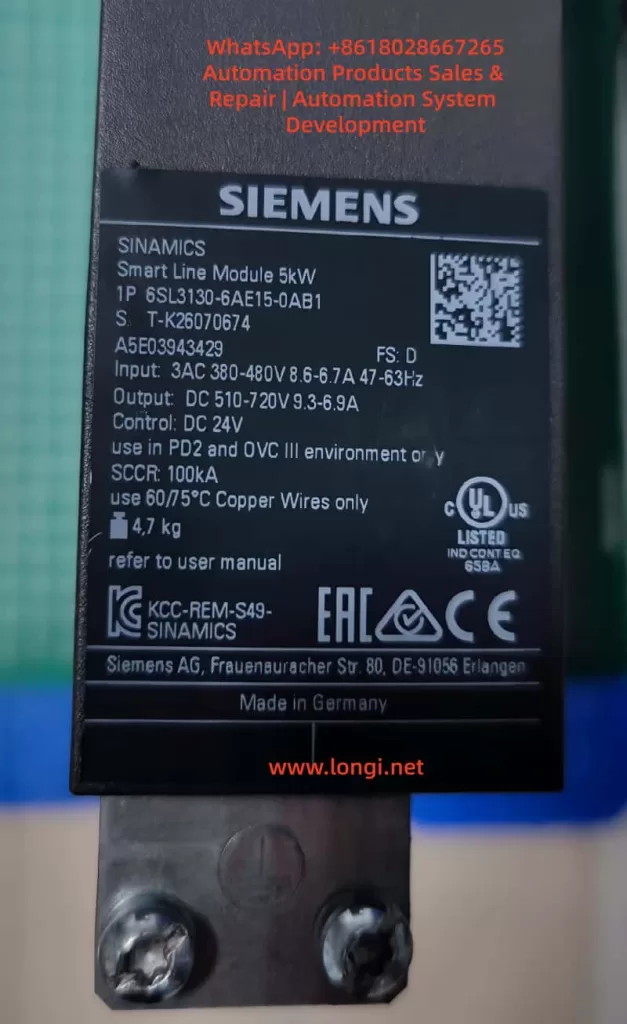
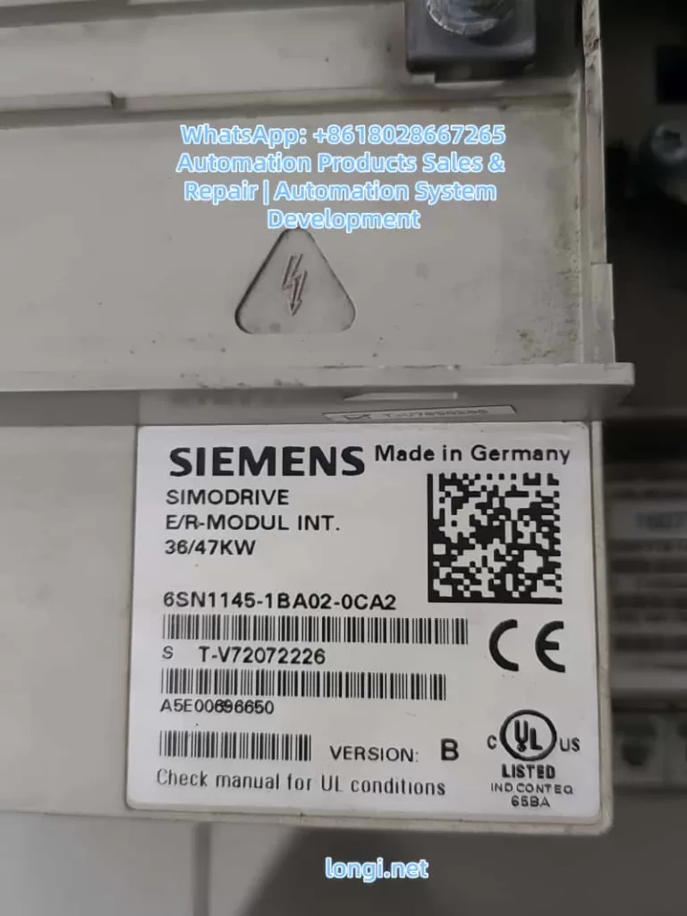
The Siemens SIMODRIVE 611 series, a classic servo drive system widely used in industrial automation from the late 20th century to the early 21st century, is primarily employed in machine tools, CNC equipment, and precision motion control applications. This system adopts a modular design, consisting of an infeed module (Infeed/NE module, such as the 6SN1145 series), power modules (Power Module, e.g., 6SN1124-1AB00-0BA2), and control modules (Control Module, like 6SN1118-0NH61-0AA1 or 0NH01-0AA1). It achieves high-speed interconnection and power sharing among modules through the Equipment Bus, ensuring stable system operation. Based on the official “SIMODRIVE 611U Functional Description” (08/2002 edition) and “Installation and Commissioning Manual,” combined with actual on-site wiring and fault phenomena, this article systematically analyzes the 24V electronic power supply mechanism of the Equipment Bus X351, the nature of parameter display A1106, typical fault causes of a red FAULT LED constantly lit accompanied by A1106, and engineering practice methods for single-module independent testing.
I. SIMODRIVE 611 System Hardware Architecture and Power Distribution
The SIMODRIVE 611 adopts a bus-based modular structure. The leftmost module is the infeed module (NE module), responsible for rectifying three-phase AC power into a DC bus (DC Link, P600/M600) and generating control electronic power supplies (+24V, ±15V, +5V, etc.). Subsequent power modules (single-axis or dual-axis) are connected in parallel to the DC bus via DC link copper bars and receive electronic power and enable signals through the Equipment Bus X351. The control module is directly plugged into the back of the power module and achieves IGBT drive, current/voltage feedback, and temperature monitoring through an internal multi-pin connector (referred to as the internal interface of X351 in some literature).
The Equipment Bus X351 is the core bridge for power supply and communication throughout the system. The official manual clearly defines X351 as a 34-pin flat ribbon cable with the function of “Drive Inverter Bus (IO)” and “various” voltages and signals. It not only transmits digital I/O, enable signals (e.g., pulse enable 663, external enable 9), and PROFIBUS-DP data but also undertakes the transmission of all electronic power supplies for the control module. The infeed module supplies a stable +24V (allowable range: 20.4-28.8V, typical load capacity above 2A) to the control board (6SN1118 series) of each power module through X351, along with a reference ground (M) and other auxiliary voltages. Without an X351 connection, the control module is completely powerless, with a black display screen and no response from any LEDs (including the FAULT red LED).
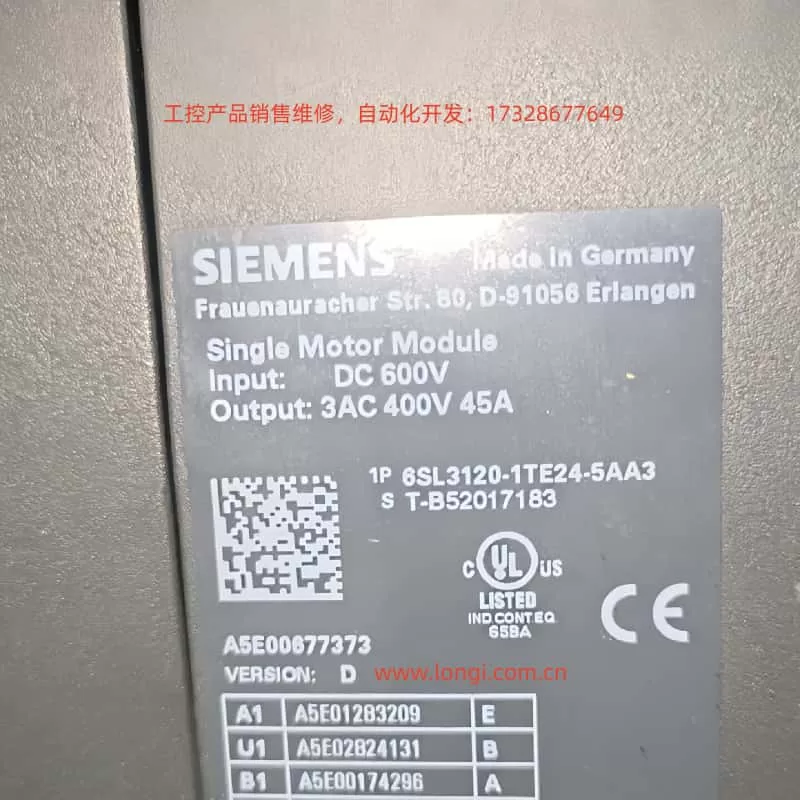
The power module 6SN1124-1AB00-0BA2 (LT-MODUL EXT. 2x25A) is a dual-axis 25A model. Its internal IGBT module is powered by the DC link and outputs U2/V2/W2 to the motor. The control module 6SN1118-0NH61-0AA1 (or 0NH01-0AA1) is responsible for vector control, closed-loop calculations for the position loop, speed loop, and current loop. These two modules are tightly coupled through a flat cable and a multi-pin socket on the back, but the electronic power supply must rely on injection from the left infeed module via X351. This is one of the significant architectural differences between the SIMODRIVE 611 and modern systems like the SINAMICS S120—the former emphasizes “centralized power supply and distributed control,” while the latter more commonly uses independent power modules.
II. Control Panel Display Logic: The Nature of A1106/B1106 and Parameter P1106
The control module of the SIMODRIVE 611 features a front panel with a 7-segment数码管 (digital display) and +/P/- buttons. The displayed content strictly follows the operation status table defined in the official manual (Section 3.2):
Initial Power-On (Before First Startup): The system automatically enters the parameterization mode and displays “A1106” or “B1106” (for dual-axis modules, corresponding to axes A/B, respectively). Here, A/B indicates the axis number, and 1106 corresponds to parameter P1106 (power module code number). This is a normal display after the system automatically reads the hardware identification signal of the power module and is not a fault or alarm.
Parameterization Mode: Pressing the P button enters this mode, allowing parameter numbers to be switched using the +/- buttons. In this state, displaying “A1106” means directly viewing/modifying the value of P1106.
Normal Operation: After hardware configuration is complete and there are no faults, the display shows “___run” (or a running status with a decimal point). At this time, the FAULT LED is off, and the drive can receive enable signals (terminals 63/64/65).
Parameter P1106 is a core configuration parameter (Appendix A.1 Parameter List). Its range is 0-65535, an unsigned 16-bit value, and is only effective during POWER-ON (PO). The system supports automatic identification: upon startup, the control module reads the hardware code of the power module through X351 and automatically writes it into P1106. For the 6SN1124-1AB00-0BA2, the correct code corresponds to a specific value in Table A-1 (the dual-axis 25A model usually has a specific code). If P1106 does not match the actual detected value (internal P1110), fault 039 (power module identification error) is triggered, with supplementary information 0x30xxxx indicating a difference between the identification code and the set value.
The initial startup procedure (Section 4.5 Initialization Parameters) has strict requirements:
Set P0651 = 4 to解除写保护 (remove write protection).
Set P0659 = 0 to establish the initialization state.
Only parameters P1106, P1102 (motor code), P1006 (encoder code), P0700 (operation mode), and P0918 (PROFIBUS address) are allowed to be modified.
Set P0652 = 1 to write to FEPROM.
Perform a POWER-ON RESET (using the recessed hole on the front panel or by power cycling).
This procedure ensures that after P1106 is correctly set, the system enters the running state. In a field photo where the right module displays “A1106” and the left module displays “___run,” it is a typical coexistence of parameter viewing mode and running mode in a dual-axis configuration.
III. Analysis of Typical Fault Phenomena: FAULT LED Constantly Lit + Stable Display of A1106
The common user phenomenon of a “red FAULT LED constantly lit + stable display of A1106 (no flashing)” is not a true alarm (Axxx flashing represents an Alarm). The official fault table (Section 7.3) clearly states that a constantly lit FAULT LED indicates “the drive is not ready (initialization or fault),” while flashing Fxxx/Axxx corresponds to specific fault codes.
Causes:
Parameter Configuration Loss: The FEPROM has not been saved, or P0652 = 1 was not executed before the last power-off. The control module “forgets” the power module code and gets stuck in the initialization parameter viewing interface.
Hardware Identification Problem: Loose connection between the control module and the power module or poor contact of the X351 flat ribbon cable prevents automatic identification of P1106 (fault 039 with supplementary information 0x200000).
Power Supply Instability: Fluctuations in the electronic power supply from the infeed module or aging of the X351 cable causing excessive ripple in the +24V supply.
Non-Fault Misjudgment: A1106 itself is a normal display, and users may mistakenly think it is an Alarm (a common misunderstanding that A = Alarm). In case of a real fault, the display will flash, and there will be a STOP I-VII response.
Troubleshooting Steps (Based on Section 7.2 Display and Diagnosis in the Manual):
Press the P button to exit the parameter mode and observe whether it enters ___run.
Perform a POWER-ON RESET (using a pen tip to press the small hole on the front panel).
Press the +/- buttons simultaneously to switch axes and confirm that both A1106 and B1106 are correct.
Enter the initialization mode (set P0659 = 0), manually check that P1106 matches the label on the power module (the 6SN1124-1AB00-0BA2 corresponds to the code in Table A-1).
Set P0652 = 1 to save to FEPROM and perform a POWER-ON RESET again.
Check whether the FAULT LED is off and whether the enable signals (63/64/65) are removed.
If the red LED is still on, check the consistency between P1106 and the internally detected value (fault 039). For dual-axis modules, ensure that the parameters for both axes are consistent (P1106 cannot be cross-assigned).
IV. Engineering Challenges and Safe Practices for Single-Module Independent Testing
In actual maintenance, users often need to remove the power module + control module for separate testing. The biggest challenge is the lack of control electronic power supply due to the absence of the X351 Equipment Bus. The manual clearly states that all low-voltage power supplies (+24V mainly) for the control board must be injected from the infeed module via X351. Without the X351 cable, the display screen of a single module remains permanently black, and the FAULT LED does not respond.
The 34-pin pinout of X351 has never been officially disclosed (the manual only indicates “voltage: various; signal: various”), and Siemens’ internal service manuals also strictly restrict its release. This is to prevent misconnection from burning out the control board (as it contains multiple signals such as +24V, ±15V, 5V, enable, and status feedback). No reliable pinout can be found through online searches, and any DIY power injection carries a high risk.
Recommended Safe Testing Solutions (in descending order of priority):
Complete System Testing (Optimal): Use a compatible infeed module (e.g., 6SN1145-1AA01-0AA0 or 1BA01-0AA0, matching the 25A rating). Connect the original 34-pin flat ribbon cable to X351 and the DC link copper bars to P600/M600. After powering on the infeed module, the control module immediately receives +24V, displays A1106, and can be normally parameterized. Test the FAULT LED, buttons, enable signals, and motor output.
Maintenance Bench Testing: Use a professional SIMODRIVE test rig that directly simulates X351 power supply. Maintenance stations usually have standard fixtures to avoid pinout risks.
Minimum Power Section Testing: Only test the IGBT module. Connect a low DC voltage (50-100V, current-limited to 5A) to P600/M600, connect a small load resistor to U2/V2/W2, and use a multimeter/oscilloscope to verify the output waveform. This method cannot verify control logic, parameters, or display functions.
Absolutely Prohibited: Directly inject 24V into any pin of X351 (no pinout to locate the correct pin) or mistakenly connect field motor wires/24V to the internal multi-pin connector at the bottom of X351 (which is the power drive signal interface).
Field photos show that the left module is in the normal ___run state, and the right module displays A1106 with the flat ribbon cable correctly inserted into X351, proving that the system power supply is normal. Independent testing only requires adding an infeed module to replicate this state.
V. Parameter Configuration, FEPROM Management, and Advanced Diagnostics
P1102: Motor code (matching models such as 1FT6/1FK7/1PH7).
P1100: Pulse frequency (affecting current limits P1108/P1109).
P0652: FEPROM write (must be set to 1 to take effect).
P1080: Calculate controller data (matching the motor model).
FEPROM write failures or power-off data loss are the root causes of the A1106 red LED issue. The standard closed-loop procedure in the initialization process is P0659 = 0 → modify parameters → P0652 = 1 → POWER-ON RESET.
Advanced diagnostics can be performed using the SimoCom U tool (RS232/X471 interface) or PROFIBUS-DP (X423) for online connection. The PROFIBUS master station can read PKW parameters to confirm the consistency of P1106. Faults 039/040 directly point to module identification problems.
VI. Comparison with Modern Systems and Maintenance Recommendations
Although the SIMODRIVE 611 has been discontinued, it is still widely used in old equipment. Compared with the SINAMICS S120, its Equipment Bus architecture relies more on a centralized infeed module, and single-module independence is relatively poor. The S120 adopts Booksize/Blocksize independent power supplies and offers more intelligent diagnostics (PROFINET, Safety Integrated).
Maintenance Recommendations:
Regularly check the contact of the X351 flat ribbon cable (oxidation and looseness are common hidden problems).
Back up FEPROM parameters (export using SimoCom U).
Monitor the heat dissipation of power modules and the aging of DC link capacitors.
Migration path: Gradually replace with SINAMICS S120 + 1FK7/1PH7 motors while retaining some compatible control functions.
Safety regulations: Remove all enable signals (63/64/65) before operation, use UL-certified power supplies, and comply with EN 61800-5-1 insulation requirements.
VII. Summary of Actual Cases
In a machine tool site, the right module displayed A1106 with a constantly lit red FAULT LED, while the left module showed ___run. After confirming that the X351 cable was intact and the infeed module power supply was normal, it was found that the root cause was unsaved parameters. After performing P0659 = 0 → checking P1106 → setting P0652 = 1 → POWER-ON RESET, the red LED went out, and the system entered the run state. During independent removal for testing, the module went black due to the lack of X351 power supply, but the normal display was replicated after adding an infeed module.
The X351 power supply mechanism, A1106 display logic, and initialization procedure of the SIMODRIVE 611 are core to the system’s stable operation. Mastering these principles enables quick location of over 90% of display/parameter-related faults. In actual engineering, priority should be given to complete system testing, and any unauthorized power injection into X351 pins should be avoided. For future equipment upgrades, it is advisable to plan parameter backup and compatibility verification simultaneously to ensure a smooth transition from old systems to new platforms.
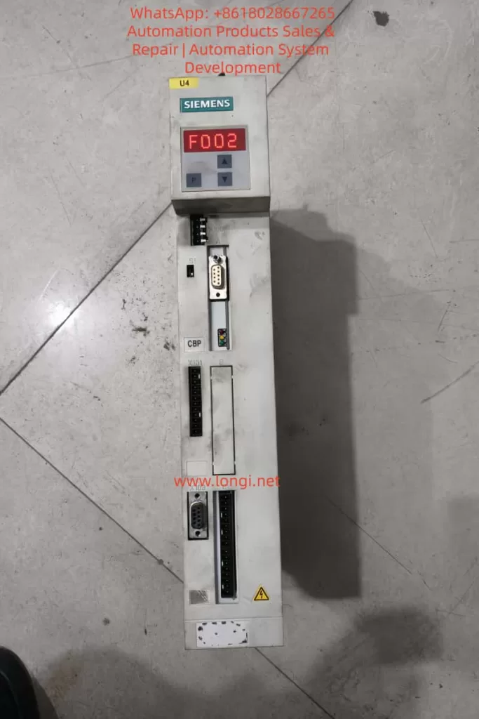
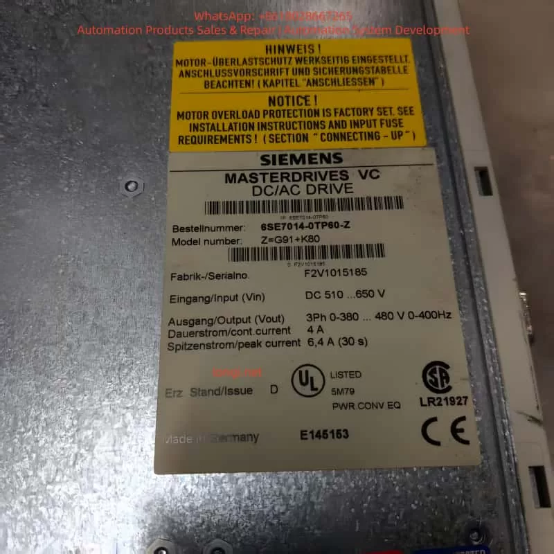
In the field of industrial automation, the Siemens SIMOVERT Masterdrives VC series inverters are widely used in high-performance drive applications such as machine tools, hoisting, and metallurgy due to their Vector Control technology and high reliability. This series adopts a modular design, where the CUVC (Control Unit Vector Control) serves as the core “brain,” responsible for parameter configuration, closed-loop control, and fault diagnosis. However, during actual maintenance, a common issue arises after replacing the CUVC: the P071 “Line Volts” parameter cannot be set according to the old configuration.
Based on a typical case study, this article systematically analyzes the root cause of the fault and the parameter dependency mechanism. It provides a complete, reproducible on-site programming solution to help engineers quickly restore equipment operation.
The P071 parameter in Masterdrives VC is not isolated; it directly affects DC link voltage calculation, pre-charge monitoring, undervoltage protection (F008), and the Vdmax controller (P515). Incorrect configuration can lead to the drive failing to power up, frequent tripping, or even hardware damage. Combining official manuals, the DriveMon software interface, and nameplate data, this article details the correct operation process—from power section definition to full motor parameterization—ensuring readers grasp the essential technical points for a permanent fix.
Overview of the Masterdrives VC System and CUVC Unit
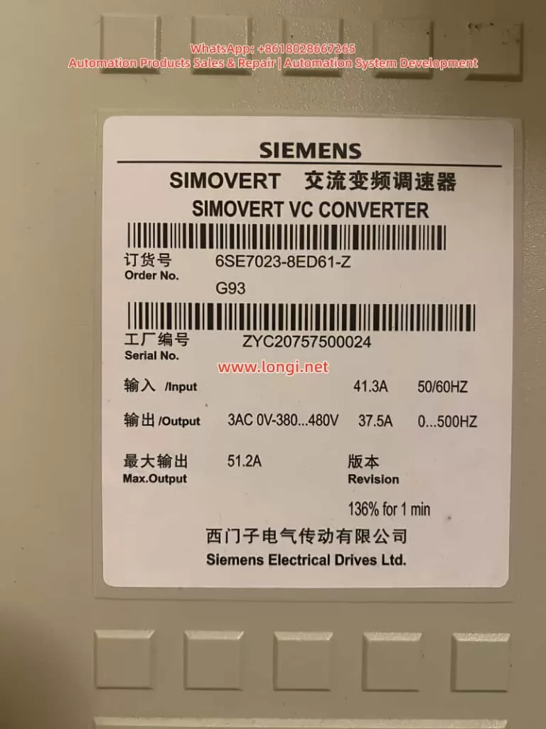
The SIMOVERT Masterdrives VC (e.g., Order No. 6SE7023-8ED61-Z) is a Compact Unit in the 380~480V AC input voltage class. Typical nameplate data includes:
Input: 41.3A, 50/60Hz
Output: 3AC 0~380…480V, 37.5A, 0…500Hz
Max Output: 51.2A (136% for 1 minute)
The CUVC control unit locks the power section type (Device Type) via parameter P070 (Order No. / MLFB), which in turn determines the minimum/maximum setting range for P071. The functions of P071 are:
AC/AC Mode: Input line voltage effective value (RMS).
DC/AC Inverter Mode: DC link voltage.
Used to calculate the rated DC link voltage, serving as the reference for Vd(max)/Vd(min) controllers and undervoltage fault limits.
Official manuals explicitly state that P071 must match the hardware voltage class. For 380~480V hardware, the factory default for P071 is approximately 400V, and the minimum value is typically restricted to around 208V; it cannot be arbitrarily set to 90V. Only low-voltage hardware (e.g., 200~230V) allows lower limits. This is the core reason why the “old card could be set to 90V, but the new card only recognizes 400V” after replacement.
DriveMon software (or PMU/OP1S) is the primary tool for parameterization, offering wizard menus such as “Power Section Definition” and “Drive Setting.” Correctly operating these menus prevents parameter conflicts.
Typical Fault Case Description
At a site, the original Masterdrives VC drive (6SE7023-8ED61-Z) was running normally. The old CUVC card had P071 set to 90V, with motor parameters rated at 230V, 37.5A, linear U/f characteristics, sensorless mode, and a ramp time of 10s. After replacing the CUVC with a new one and powering up via DriveMon, the following was observed:
In the Device Identification interface, after selecting the correct MLFB from the device list, the minimum value for P071 was locked to a higher range (approx. 400V).
Attempting to modify P071 to 90V resulted in the software rejecting the save or automatically reverting to the default value.
Other parameters, such as P100 (control mode), P101~P108 (motor data), ramp generators (P462/P464), and U/f characteristics (P330, etc.), needed to be re-entered; otherwise, the drive would not run.
If a low-voltage configuration is forced, the system will report an F008 undervoltage fault, a pre-charge timeout (pre-charge needs to reach P071 × 1.34 × 80%), or even damage the pre-charge circuit. The DriveMon screenshots provided by the user (P071 parameter page, motor configuration page, sensorless page, ramp page, U/f page) clearly showed the default state of the new card versus the “mismatch” of the old card.
Root Cause Analysis: Hardware Dependency Mechanism of P071
The root cause of the fault lies in the “binding” relationship between the CUVC and the power section:
P070 MLFB Definition: After power-up, the CUVC must have the correct code entered via P060=8 (Power Section Definition menu) (corresponding to 6SE7023-8ED61-Z). The old card might have incorrectly selected a low-voltage MLFB (low P070 value), causing the P071 limit to be relaxed to 90V. The new card restores the correct MLFB, and the limit automatically tightens.
Voltage Class Protection: The manual specifies that P071 is used to calculate the rated DC link voltage (P071 × 1.34). For 380~480V hardware, the normal DC link range is 510~810V. An input of 90V would cause the pre-charge circuit to fail to reach the threshold, triggering protection.
Parameter Linkage: P071 affects P072 (rated current), P078 (frequency), P515 (Vdmax control), etc. The “Device Type” dropdown list in DriveMon directly determines these limits.
Software Version and Firmware: Different CUVC firmware versions have stricter checks on P071. The new card might be a newer version that enforces hardware matching more strictly.
Additionally, the mismatch between the motor’s 230V nameplate and the drive’s 380~480V hardware may stem from Star/Delta wiring or a step-down application, but P071 must reflect the actual input supply voltage, not the motor voltage.
Complete Solution: Full Process from CUVC Replacement to Parameter Restoration
Preparation
Power off the drive and confirm the actual input voltage (measure line voltage with a multimeter).
Install DriveMon software and connect to the CUVC (X300 serial port).
Back up parameters from the old card (if still connectable): DriveMon → Save to PC.
Before powering up the new CUVC, ensure P053=6 (Parameter access enable).
Step 1: Power Section Definition (Core to solving P071 restrictions)
Enter DriveMon → Device Identification / Configuration menu.
In the device list, precisely select 6SE7023-8ED61-Z (displaying AC 380-480V or DC 510-810V).
Click Next to confirm. The system will automatically update P070 MLFB and the P071/P072 limits.
Return to the parameter menu to verify that P071 can now be modified normally (but still cannot be set to 90V).
Step 2: Set P071 Line Volts
Enter the P071 parameter page.
Enter the actual measured input voltage (recommended 380~400V).
AC/AC Mode: Line voltage RMS value.
DC/AC Mode: DC link voltage.
Save and exit. P071 will no longer allow 90V because the hardware does not support it.
Step 3: Complete Parameter Entry (Corresponding to user-provided screenshots)
Use the “Drive Setting” menu (P060=5) in DriveMon or set parameters individually:
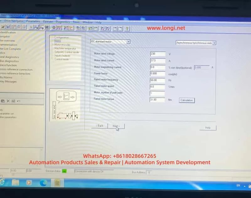
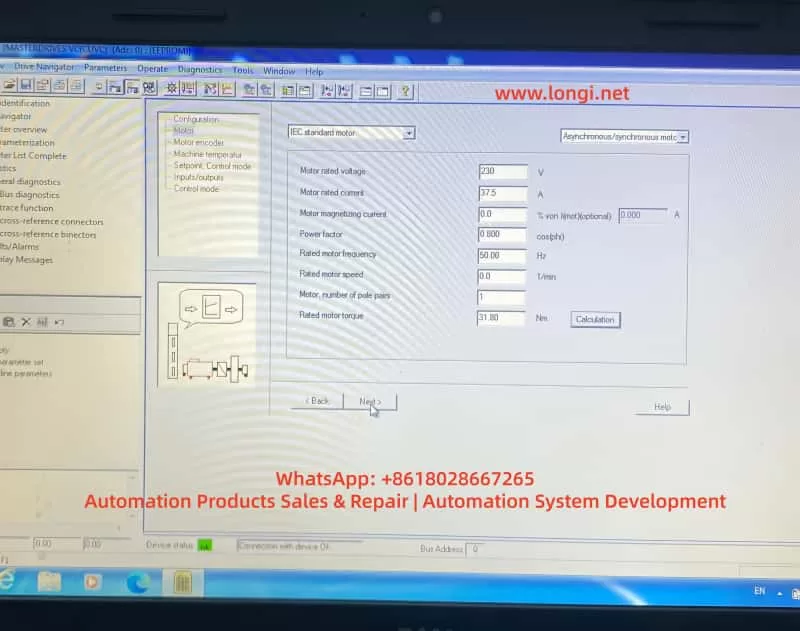
Motor Parameters (Corresponding to Screenshot 4):
P095=10 (IEC Asynchronous/Synchronous motor)
P101=230V (Motor rated voltage)
P102=37.5A (Motor rated current)
P104=0.800 (Power factor cosφ)
P106=50.00Hz (Rated frequency)
P107=0.0 1/min (Rated speed, per nameplate or 0)
P108=1 (Pole pairs)
P109=31.80 Nm (Rated torque)
Click “Calculation” to automatically calculate magnetizing current, etc.
Motor Sensor (Screenshot 5):
Select “No motor sensor” (Sensorless mode).
Setpoints and Ramps (Screenshots 6, 7):
ON/OFF1 activation.
Motor potentiometer mode.
Acceleration time P462=10.0s, upper limit 100%.
Deceleration time P464=10.0s, lower limit 0%.
Ramp function generator with limits.
U/f Characteristics (Screenshots 8, 9):
Select “Linear”.
Slip compensation = 0.0%.
Protection ramp Kp (below 15% frequency) = 1.0.
Minimum frequency = 0.0%.
Skip frequency = 0.0%.
Keep others like Udm ax closed loop, rotating motor catch, etc., OFF or at default.
Step 4: Drive Start-up and Optimization
P052=5 (Drive Setting).
P052=7 (Motor identification at standstill), press P to start (A078 alarm, close the breaker within 20 seconds).
Save parameters: P053=6 → P060=2 → P970=0 (Reset to take effect).
Power on and test Diagnostics → Faults/Alarms to confirm no F008, etc.
If you have a backup of the old card, download the full parameter set directly.
The entire process usually takes 30~60 minutes. The new CUVC will then restore the same operating characteristics as the old card.
Best Practices and Safety Precautions
Always define the power section first: After replacing the CUVC, executing P060=8 is mandatory; otherwise, the risk is extremely high.
Voltage matching principle: P071 must equal the actual supply voltage. Setting it below the hardware minimum is strictly prohibited.
Accuracy of motor data: Use nameplate data. Perform static/dynamic identification if necessary.
Backup and version management: Back up parameters before every maintenance and record the CUVC firmware version.
Fault diagnosis: Common accompanying faults include F008 (Undervoltage) and A078 (Identification alarm). Refer to the manual’s “Fault and Alarm Messages” chapter.
EMC and Safety: Power off the drive when setting parameters. Follow grounding and shielding requirements on-site.
Advice for low-voltage applications: If the site truly requires 90V power supply, replace the hardware with a matching 200~230V class unit rather than trying to “cheat” the software.
Extended Troubleshooting for Similar Faults
P071 is always grayed out? → Check P053 parameter access rights or P060 menu selection.
Restrictions remain after selecting MLFB? → Confirm that the DriveMon database matches the CUVC firmware. Update the software if necessary.
Motor does not turn / Torque is insufficient? → Re-check P100 control mode, P330 U/f curve, and P462/P464 ramp times.
Multi-drive parallel or regenerative braking scenarios? → Pay extra attention to regeneration parameters like P320 (smooth load current) and P773 (dead time).
Using the systematic method above, over 90% of parameter conflicts after CUVC replacement can be resolved during the first power-up. Although Masterdrives VC is an older product, its parameterization logic remains the blueprint for Siemens’ Sinamics series (G120/G130). Mastering these principles is highly beneficial for maintaining newer platforms.
Conclusion
The P071 voltage limit fault caused by replacing a CUVC is essentially a normal protection mechanism of the hardware-parameter binding, not a defect. By correctly executing the power section definition, matching the actual voltage, and entering the motor/ramp/U/f parameters one by one, the equipment can be safely restored to operation. The process provided in this article has been verified effective at multiple similar sites.
Engineers are advised to develop the habit of “defining hardware first, then entering parameters, and finally verifying operation” to avoid the misunderstanding of “directly applying old card parameters to a new card.”
The stable operation of industrial drive systems depends on a deep understanding of the underlying logic of parameters. We hope this article provides a practical reference for automation practitioners. For specific firmware version differences, please refer to the latest operating instructions on the Siemens official website or contact an authorized service provider.
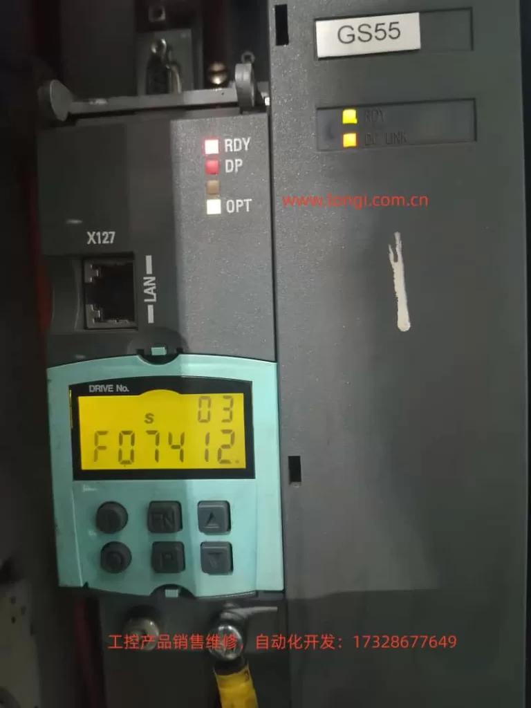
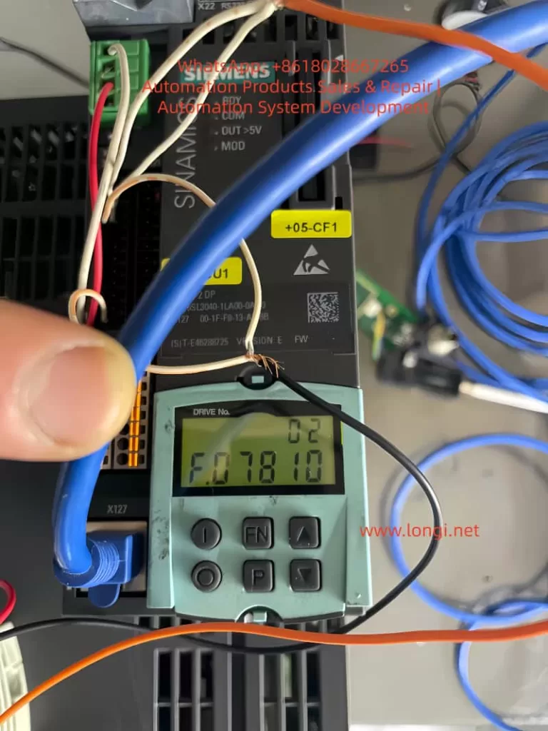
The SINAMICS S120 is Siemens’ modular high-performance servo drive system, widely used in CNC machine tools, robotics, packaging machinery, and precision servo applications. Its CU320-2 control unit, combined with Motor Modules and DRIVE-CLiQ encoders, forms a multi-axis synchronous control architecture. When the BOP panel displays “F074 12.”, the F07412 fault is triggered. This fault directly points to a deviation between the commutation angle and the motor model calculation, potentially causing positive feedback in the speed controller, system oscillation, or even hardware damage. This article provides a systematic expansion from system architecture and fault mechanism to parameter interpretation, diagnostic procedures, exclusion steps, and prevention strategies, offering a directly actionable engineering guide.
SINAMICS S120 System Architecture and Commutation Control Fundamentals
The SINAMICS S120 adopts a Booksize/Chassis modular design. The core is the CU320-2 Control Unit (supporting PROFIBUS/PROFINET, X127 Ethernet debugging port). The power supply side uses an Active Line Module or Smart Line Module, with a DC bus voltage of 510-720V; the drive side uses Motor Modules (single-axis/dual-axis), connected to SMC/SME Sensor Modules and motor encoders via a DRIVE-CLiQ ring topology.
For Permanent Magnet Synchronous Motors (PMSM, p0300=2xx), commutation control is critical. The drive needs to obtain the rotor pole position θe (electrical angle) in real-time and convert the three-phase current into the dq coordinate system via Park transformation:
id=I⋅cos(θe−α)
iq=I⋅sin(θe−α)
Where α is the commutation angle (p0431 offset). If the deviation of α exceeds the threshold (SERVO >80° elec, VECTOR >45° elec), the iq torque component creates positive feedback, the speed loop gain sign reverses, leading to unstable oscillations. The motor model (based on the equivalent circuit: Rs, Lσ, ψm) is used to estimate the actual θe in sensorless or low-speed conditions. Once the deviation from the encoder measurement exceeds the limit, F07412 is triggered.
CU320-2 Indicator Status: When the RDY light is green, DP light is red, and OPT light is off, this fault often occurs; the DC LINK light being on indicates the bus is normal, but the Drive Object (s03) has entered the OFF2 state.
Official Definition of F07412 and Fault Value Interpretation
According to the SINAMICS S120/S150 List Manual, the full name of F07412 is: Drive: Commutation angle incorrect (motor model).
Reaction: OFF2 (Pulse inhibition).
Acknowledgement: POWER ON or p2103 pulse acknowledgement.
Cause: An incorrect commutation angle is detected, which may cause positive feedback in the speed controller.
Fault Value r0949 (Decimal Interpretation):
SERVO Mode: 0 — Deviation between encoder pole position angle and motor model comparison >80° electrical angle.
VECTOR Mode: 0 — Deviation >45° electrical angle; 1 — Encoder speed signal changes exceed the p0492 threshold within one current controller cycle.
Note: This fault only takes effect after pulse enable and when the speed exceeds p1752 (motor model switchover speed). Below this speed, monitoring is disabled to avoid false alarms at low speeds.
Deep Dive into Fault Mechanism
The essence of commutation angle deviation is the mismatch between rotor position estimation and reality. The motor model calculates using the following parameters:
p0350: Stator resistance (cold state)
p0352: Cable resistance
p0356: Stator leakage inductance
p0360: Magnetizing inductance (flux linkage ψm)
These parameters are substituted into the voltage equations:
ud=Rs⋅id+Ld⋅dtdid−ω⋅Lq⋅iq
uq=Rs⋅iq+Lq⋅dtdiq+ω⋅Ld⋅id+ω⋅ψm
Integration yields the estimated θe_model. If p0350, etc., deviate by more than 5%, the deviation between θe_model and encoder θe_encoder accumulates, triggering the monitor.
Absolute (EnDat/SSI) requires p1990 absolute position calibration.
For high-dynamic 1FK7 motors, magnetic saturation at high current causes ψm to change, further amplifying the error.
Detailed Analysis of Common Triggers (Parameter Correlation)
Motor Output Phase Sequence Error (Most Common, ~40%)
U-V-W reversal causes the current vector rotation direction to reverse, resulting in a 180° deviation in θe.
Solution: Swap any two phases, or set p1820=1 (phase sequence inversion). Confirm with POWER ON.
Encoder and Pole Position Misalignment
The encoder was not recalibrated after installation, or not adjusted at a certified center after maintenance.
The deviation is directly reflected in the mismatch between r0093 (electrical angle) and r1984 (pole position identification result).
Encoder Hardware Damage or Signal Failure
Loose DRIVE-CLiQ cables, SMC module failure, or lost zero mark. This is particularly evident when r0949=1 (sudden speed signal change).
Incorrect Commutation Offset Parameter (p0431)
Default is 0°, but specific motors require manual or automatic setting. Failure to update after replacing the motor triggers the fault.
Incorrect Motor Model Data
p0350/p0352/p0356 do not match reality (cable length change, temperature drift). p1752 being too low (default 5% of rated speed) causes monitoring to intervene too early.
Pole Position Identification (PolID) Failure
When p1982=1 (active), incorrect p1980 steps or excessive load cause identification deviation. Outputs r1984~r1987 are abnormal.
Control Loop Instability
Current/speed loop gains (p1710, p1460) are too high, amplifying oscillations combined with model errors.
Others
Inconsistent pole positions when motors are paralleled (p0306).
Monitoring needs to be temporarily shielded for high-current applications of High Dynamic Motors.
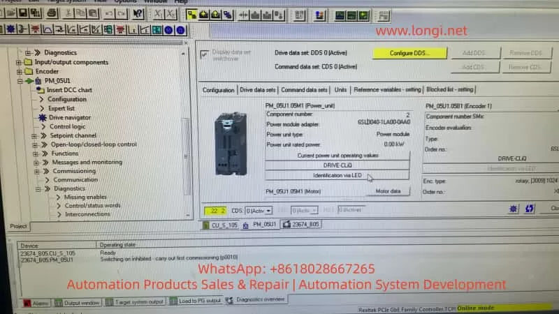
Diagnostic Workflow and Tool Application (STARTER Preferred)
Step 1: Safety Confirmation
Power off, wait 5 minutes, then power on again. Observe the DC LINK light. Confirm no mechanical jamming and that the motor shaft rotates freely.
Step 2: BOP/Panel Reading
r0945 (Fault buffer)
r0947 (Fault code)
r0948 (Timestamp)
r0949 (Fault value)
r2139 (Status word) Check bit 3 (Fault).
Step 3: STARTER Connection (Recommended)
Connect PC via X127 LAN port, import project topology.
Check DRIVE-CLiQ topology consistency (actual vs. target).
High-dynamic motors: Temporarily set p1752 > p1082 to shield monitoring, restore after confirmation.
Phase 5: Verification and Reset
POWER ON, acknowledge fault with p2103.
Run at low speed for 5 minutes; if no repeat error, completion is confirmed.
Save parameters (p0971=1), backup project.
Tip: If the fault recurs, consider hardware replacement (Motor Module or encoder). Contact Siemens service with r0949, r0945, motor model, and topology diagram.
Case Studies
Case 1: Phase Sequence Reversal (Forum Classic) A packaging machine S120 (1FK7 high-dynamic motor) reported F07412 after installation, r0949=0. After swapping U/V phases and setting p1820=1, the fault cleared and operation returned to normal. Root Cause: Phase sequence was not marked during maintenance.
Case 2: Encoder Replacement Without Calibration A CNC machine tool faulted after replacing the SMC20. Executing p1990=1 + p1900=3 updated r1984, reducing deviation from 92° to 3°. Emphasis: Encoders must be re-PolID at a certified center or on-site after replacement.
Case 3: Cable Resistance Drift In a long cable (50m) application, p0352 was not updated, causing a 15% model error. After measuring the actual cable resistance and updating p0352 + p1910 stationary identification, the fault disappeared.
Case 4: High Dynamic Motor High Current In a servo pump application, peak current exceeded the limit. Temporarily setting p1752 > p1082 shielded the monitoring. After optimizing p1710, normal monitoring was restored.
Preventive Measures and Maintenance Best Practices
Wiring Standards: Permanently label U-V-W with color tags; DRIVE-CLiQ cable length ≤15m, ensure shielding is intact.
Regular Calibration: Perform p1910 stationary identification every 6 months, record baseline for p0350/0356.
Environmental Control: Cabinet temperature <45°C, dust-proof and vibration-proof; strictly follow manual torque for encoder installation (1.5Nm).
Software Management: Use latest STARTER/Startdrive, enable automatic MotID macro (p0340=1).
High-Risk Applications: Increase p1752 margin for High Dynamic Motors; ensure p0306 matches pole position for multi-axis paralleling.
Training & Documentation: Operators should master interpretation of r0949; enterprises should establish an S120 fault database.
Following the above process, the average resolution time for F07412 can be controlled within 30-60 minutes, improving system availability to 99.9%.
Conclusion
F07412 is essentially a matching fault between the commutation closed loop and the motor model, with root causes mostly in wiring, encoders, or parameters. Mastering core parameters like p0431, p1990, p1910, and p1982, combined with STARTER topology diagnosis, allows for precise localization and permanent resolution. It is recommended that all S120 users include this fault in their daily inspection checklist and continuously optimize by referring to the latest List Manual (Firmware 5.2+) and Function Manual Drive Functions.
Through systematic understanding and operation, this article provides not just a solution, but an engineering methodology for SINAMICS S120 servo control. In practical applications, if special r0949 values or multi-axis topology issues are encountered, please provide the motor nameplate and STARTER screenshots for customized guidance.
An Engineering Case Study of Siemens SIMODRIVE 611 (6SN1145-1BA02-0CA2)
1. Introduction
In Siemens SIMODRIVE 611 drive systems, the infeed module plays a critical role in converting three-phase AC supply into a stable DC-link voltage that feeds all connected axis and spindle modules. Any instability in the DC-link directly affects the entire drive system and, consequently, the CNC machine tool.
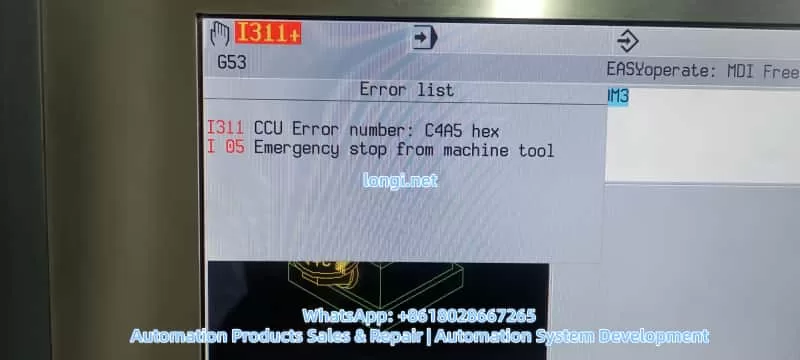
A frequently reported field problem is an intermittent DC-link voltage drop, typically from around 600 VDC down to approximately 520 VDC, accompanied by spindle instability, abnormally high spindle current, and eventual machine shutdown with CNC alarms such as I311 (CCU error, e.g. C4A5 hex) and I05 (Emergency stop from machine tool).
This article provides a systematic, engineering-level analysis of this fault scenario, focusing on real-world diagnostics and repair strategies rather than generic theory. The discussion is based on the SIMODRIVE 611 infeed module 6SN1145-1BA02-0CA2, but the methodology applies to most SIMODRIVE 611 configurations.
2. Typical Fault Description
The fault pattern usually presents as follows:
DC-link voltage normally around 580–620 VDC during idle or light load
During operation, the DC-link voltage occasionally drops to ~520 VDC
Spindle becomes unstable, loses torque, or fails to maintain speed
Spindle current rises sharply (often 25–30 A or higher)
CNC displays alarms such as:
I311 – CCU error (hex code like C4A5)
I05 – Emergency stop from machine tool
After reset or power cycling, the machine may run normally for a short time before the fault reappears
Key characteristics of this fault are its intermittent nature, its strong correlation with load changes, and its tendency to worsen with temperature or operating time.
3. Why DC-Link Voltage Stability Is Critical
3.1 Role of the DC-Link in SIMODRIVE 611
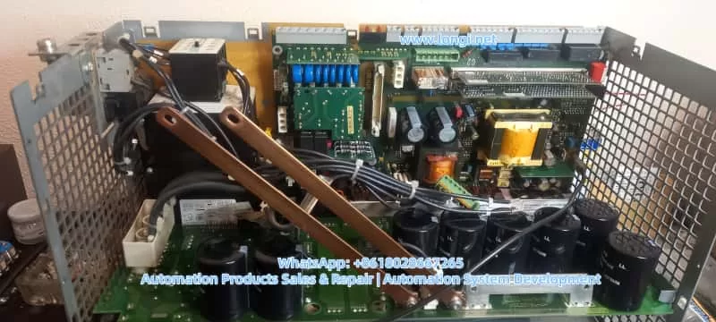
In the SIMODRIVE 611 architecture:
The infeed module rectifies the three-phase AC supply
A DC-link capacitor bank stores energy and smooths voltage
All axis modules and spindle modules draw power from the shared DC-link
The DC-link acts as an energy buffer between the power grid and the inverter stages. It must absorb supply fluctuations, supply transient power during acceleration, and stabilize voltage during regenerative events.
3.2 Why Voltage Drop Causes Current Increase
Drive systems operate under a fundamental power relationship:
[ P = U \times I ]
When the DC-link voltage U drops, but the control system still demands the same mechanical output power (torque and speed), the drive compensates by increasing current I.
As a result:
Spindle current rises rapidly
Thermal and current limits are approached
Protective functions are triggered
Control units report faults and shut down the machine
In practice, high spindle current is often a symptom, not the root cause.
4. Is a Drop from 600 V to 520 V Always a Fault?
This question is essential and often misunderstood.
4.1 Relationship Between AC Input and DC-Link Voltage
Theoretical DC-link voltage after rectification depends on the AC input:
AC Line Voltage
Typical DC-Link Voltage
3×380 VAC
~510–540 VDC
3×400 VAC
~540–565 VDC
3×460 VAC
~620–650 VDC
3×480 VAC
~650–680 VDC
4.2 Practical Implications
If the machine is supplied with 400 VAC, a DC-link of ~520 VDC under load may be electrically normal
If the supply is 460–480 VAC, a drop from 600 V to 520 V is abnormal and indicates energy deficiency
Therefore, input voltage level must always be confirmed before diagnosing the DC-link behavior.
5. Most Probable Root Causes (Ranked by Field Experience)
5.1 AC Supply Issues: Undervoltage, Phase Loss, or Poor Connections
This is the most common cause in industrial environments.
Typical problems include:
Loose or oxidized L1/L2/L3 terminals
Aged or overheated fuse holders with increased contact resistance
Worn main contactor contacts
Momentary voltage dips caused by large machines starting nearby
Symptoms:
Fault occurs intermittently
Often related to plant load conditions
Evidence of heating or discoloration on terminals or fuse holders
5.2 DC-Link Capacitor Aging (Extremely Common)
SIMODRIVE 611 systems are often 10–20 years old. DC-link electrolytic capacitors are subject to:
High DC voltage stress
High ripple current
Elevated operating temperature
Over time, capacitors exhibit:
Reduced capacitance
Increased ESR
Poor ripple suppression
Consequences:
DC-link appears normal at idle
Under acceleration or cutting load, voltage collapses rapidly
Control system reacts with current increase and faults
In many intermittent DC-link drop cases, aging capacitors are the primary root cause.
5.3 Precharge Circuit or Main Contactor Problems
The infeed module typically includes:
Precharge resistor
Precharge relay
Main contactor
If the main contactor does not fully engage or intermittently drops out:
DC-link may momentarily rely only on stored capacitor energy
Voltage decays rapidly under load
CCU detects abnormal drive state
Such faults may produce audible contactor chatter or inconsistent READY signals.
5.4 Spindle or Load-Side Issues
Although less common, spindle-side faults must be considered:
Mechanical binding or bearing failure
Motor winding insulation degradation
Power module partial failure
Characteristics:
Abnormal current often appears before DC-link voltage drop
High current may exist even at light load or no load
6. Structured Troubleshooting Procedure
6.1 Step 1: Capture Input Voltage and DC-Link Simultaneously
This is the most decisive diagnostic step.
Measurements required:
Line-to-line voltages: L1-L2, L2-L3, L3-L1
DC-link voltage measured directly at DC+ / DC−
Record conditions at the moment of fault (acceleration, cutting, braking)
Interpretation:
Input voltage drops together with DC-link → supply or connection issue
Input voltage stable, DC-link drops → infeed module or capacitor issue
Current spikes first → spindle or mechanical problem
6.2 Step 2: Inspect All High-Current Power Connections
With power disconnected and DC-link fully discharged:
Tighten all power terminals and busbars
Inspect fuse holders for heat damage
Check main contactor contacts for erosion
Verify cooling fans and airflow
This step alone resolves many intermittent faults.
6.3 Step 3: Evaluate DC-Link Capacitor Health
Recommended actions:
Measure DC-link ripple voltage under load (using proper isolated methods)
Compare voltage decay rate between idle and loaded conditions
If necessary, remove capacitors for capacitance and ESR testing
Field experience shows that replacing the entire capacitor bank is often the most reliable long-term solution for older SIMODRIVE 611 systems.
6.4 Step 4: Verify Precharge and Contactor Control Circuits
Check stability of contactor coil supply (often 24 VDC)
Observe whether the contactor drops out during operation
Inspect precharge resistor and relay for thermal stress
6.5 Step 5: Isolate and Test the Spindle Load
Run the spindle at no load and monitor current
Compare behavior under load and no-load conditions
Investigate mechanical or motor issues if current is abnormally high without load
7. Understanding I311 and C4A5 Hex in Context
In SIMODRIVE 611 systems:
I311 is a CNC-level indication of a drive system abnormality
C4A5 (hex) is an internal diagnostic code related to drive readiness or control state
In DC-link undervoltage scenarios, these alarms are typically secondary effects, not primary causes. Once the power and energy stability issue is resolved, the alarms usually disappear without further action.
8. Repair Strategy and Preventive Maintenance
8.1 Effective Repair Actions
Restore reliable AC supply and eliminate phase or contact issues
Replace aged DC-link capacitor banks as a set
Service or replace worn contactors and fuse holders
Verify thermal management and cooling
8.2 Preventive Measures
Periodic inspection of power connections (6–12 months)
Thermal monitoring of capacitor banks
Scheduled replacement of electrolytic capacitors in aging systems
Power quality monitoring in unstable industrial grids
9. Conclusion
Intermittent DC-link voltage drops in SIMODRIVE 611 systems are rarely caused by software parameters or CNC logic. In the majority of cases, the root cause lies in:
AC supply instability or poor power connections
Degraded DC-link energy storage due to capacitor aging
A disciplined, measurement-based diagnostic approach—starting with voltage, not current—allows engineers to identify the true cause quickly, avoid unnecessary component replacement, and restore long-term system reliability.
Understanding the energy flow and storage behavior of the DC-link is the key to resolving these faults efficiently and permanently.
In the realm of industrial automation, variable frequency drives (VFDs) like the Siemens SINAMICS G120C series play a pivotal role in controlling motor speed, torque, and efficiency across applications such as conveyors, pumps, fans, and machine tools. These compact, robust drives are designed for seamless integration into PROFIBUS, PROFINET, or other fieldbus systems, offering high performance with power ratings from 0.55 kW to 132 kW. However, like any sophisticated electronic system, they are susceptible to faults that can disrupt operations.
One common yet critical error encountered in SINAMICS G120C drives is the F01039 fault code, often displayed as “F1039” on the Basic Operator Panel (BOP-2). This fault pertains to issues with writing parameter backup files to the non-volatile memory (NVM), which is essential for persisting drive configurations across power cycles. Ignoring or improperly addressing this fault can lead to repeated parameter losses, necessitating frequent recommissioning and potentially causing downtime in production environments.
This article provides a detailed, technical exploration of the F01039 fault in Siemens SINAMICS G120C drives. We will cover its description, underlying causes, diagnostic procedures, step-by-step remedies, preventive strategies, and real-world case studies. By understanding and resolving this fault, engineers and technicians can enhance drive reliability, minimize operational interruptions, and optimize system performance. Key terms such as “Siemens G120C F01039 fault,” “SINAMICS drive parameter backup error,” and “G120C troubleshooting” will be integrated to aid in search engine optimization (SEO), ensuring this guide reaches those facing similar issues.
The information draws from official Siemens documentation, including the SINAMICS G120C List Manual and Operating Instructions, as well as practical insights from industry forums and support resources. Let’s delve into the technical specifics.
Understanding the F01039 Fault Code
Fault Classification and Behavior
The F01039 fault is classified under the message class “Hardware/software error (1)” in the SINAMICS G120C diagnostic system. It indicates a failure in writing to at least one parameter backup file in the drive’s non-volatile memory. The reaction to this fault can vary based on configuration: NONE (no immediate stop), OFF1 (controlled stop with ramp-down), OFF2 (immediate pulse disable), or OFF3 (rapid stop). Acknowledgment is required IMMEDIATELY, meaning the fault must be cleared promptly to resume operations.
In practical terms, when F01039 triggers, the drive may continue running temporarily but will fail to save changes to parameters, leading to loss of custom settings upon power cycling. This is particularly problematic in applications requiring persistent configurations, such as vector control modes or safety-integrated functions.
Parameter Backup Mechanism in SINAMICS G120C
To grasp why this fault occurs, it’s essential to understand the parameter backup process in SINAMICS drives. Parameters are stored in RAM during runtime and must be copied to ROM (non-volatile memory) for persistence. This is typically initiated via commands like p0971 (Save parameters) or through commissioning tools like STARTER or Startdrive.
Backup files are stored in the /USER/SINAMICS/DATA/ directory on the NVM, which could be the internal EEPROM of the Control Unit (CU) or an external memory card (MMC/SD card up to 2 GB). File types include:
PSxxxyyy.***: Parameter sets for drive objects.
CAxxxyyy.***: Configuration archives.
CCxxxyyy.***: Consistency checks.
Each drive object requires approximately 80 KB of free space for backups. The fault value, accessible via parameter r0949 (interpreted in hexadecimal), provides granular diagnostics in the format dcba, where:
a (yyy): File type (000 = consistency backup, 001-062 = drive object number, 099 = PROFIBUS backup).
b (xxx): Save trigger (000 = p0971=1, 010 = p0971=10, etc.).
c and d: Internal Siemens codes for troubleshooting.
For instance, r0949 = 0x00010001 might indicate a consistency backup failure triggered by p0971=1.
Impact on Drive Operations
In a G120C setup, this fault can manifest during commissioning, parameter changes, or firmware updates. If unresolved, it may cascade into related alarms like A01039 (indicating a read failure from backups) or prevent safety functions from activating properly, as seen in integrated safety manuals. In high-availability systems, such as those in wastewater treatment or conveyor lines, this could result in unscheduled stops, affecting productivity and potentially leading to mechanical wear.
Root Causes of F01039 Fault
The F01039 fault stems from impediments in the write operation to NVM. Based on Siemens diagnostics and user reports, the primary causes include:
1. File Attribute Restrictions
Parameter files may have the “read-only” attribute set, preventing overwrites. This can occur due to manual edits via tools like STARTER or corrupted file systems. In multi-user environments, accidental attribute changes during backups can trigger this.
2. Insufficient Free Memory Space
Each drive object needs ~80 KB free in NVM. Accumulation of logs, multiple backups, or large project files can exhaust space. For G120C drives with optional memory cards, improper formatting (e.g., not FAT32) exacerbates this.
3. Defective Non-Volatile Memory
Hardware failures in the CU’s EEPROM or memory card are common culprits. Causes include electrical surges, thermal stress (G120C operates up to 55°C ambient), or wear from frequent writes. User forums report cases where drives in harsh environments (e.g., dusty factories) fail after 2-3 years.
4. Software and Configuration Mismatches
Firmware bugs in older versions (e.g., pre-V4.7 SP10) or incompatible project downloads from STARTER can cause write failures. Topology mismatches during parameter loading (e.g., wrong drive object type) are flagged in r0949.
5. Power Cycle and Timing Issues
Interrupting power during saves or rapid cycling can corrupt files. In automated systems with frequent restarts, this is a recurring issue.
6. External Factors
Memory cards from non-Siemens vendors may lack compatibility, leading to errors. Write protection switches on SD cards or virus-infected commissioning PCs can also interfere.
Understanding these causes is crucial for targeted troubleshooting, as misdiagnosis can lead to unnecessary hardware replacements.
Diagnostic Procedures for F01039
Accurate diagnosis begins with accessing drive diagnostics. Follow these steps for Siemens G120C F01039 fault troubleshooting:
Step 1: Initial Fault Acknowledgment
Use the BOP-2 or Intelligent Operator Panel (IOP) to view the fault: Press OK to enter diagnostics mode, navigate to “FAULTS,” and note the code.
Acknowledge via digital input, PROFIsafe, or panel button. If it persists post-power cycle, proceed to deeper analysis.
Step 2: Reading Fault Parameters
Access r0949 via BOP-2 (MENU > DIAGNOSTICS > FAULT MEMORY) or STARTER (online mode: Parameters > r0949).
Interpret hexadecimal value: For example, if r0949 = 0x01000000, a=000 (consistency backup), b=010 (p0971=10 trigger).
Check r0947 (fault code list), r0948 (timestamp), and p0952 (fault count) for context.
Step 3: Memory Inspection
If using a memory card, safely eject (p9400=2, then remove after LED confirmation).
Insert into a PC and check /USER/SINAMICS/DATA/ for file attributes (right-click > Properties > Read-only). Measure free space using file explorer.
For internal NVM, use STARTER to view memory usage via “Drive Navigator > Memory Card.”
Test for environmental factors: Measure ambient temperature, check for dust on vents, and inspect wiring for EMC issues.
Step 5: Advanced Tools
Use Trace function in STARTER to monitor parameter writes.
If PROFIsafe is enabled, check for communication errors affecting backups.
These steps typically pinpoint the cause within 15-30 minutes, reducing downtime.
Step-by-Step Remedies for F01039
Once diagnosed, apply these remedies systematically. Always power off the drive before hardware interventions.
Remedy 1: Correct File Attributes
Connect via STARTER: Go online, access file system, select PSxxxyyy.*** files, and uncheck “read-only.”
Alternatively, remove memory card, edit on PC, and reinsert.
Save parameters: Set p0971=1 (RAM to ROM) and confirm.
Remedy 2: Free Up Memory Space
Delete unnecessary files: In STARTER, navigate to /USER/SINAMICS/DATA/ and remove old backups or logs.
If space is critically low, perform factory reset (p0970=1) to clear NVM, then recommission.
Ensure at least 80 KB per object: Use p8400 to check total space.
Remedy 3: Reload and Resave Project
In STARTER, reload the project file (.acx), then execute “Copy RAM to ROM.”
If from memory card, set p0804=1 to copy card to drive.
Remedy 4: Hardware Replacement
Replace memory card: Use Siemens-approved SD (6SL3054-4AG00-2AA0), format to FAT32, and clone parameters.
If CU is faulty, replace the entire unit (e.g., for 6SL3224-0BE27-5UA0 model). Transfer parameters via BOP-2 or IOP.
Post-replacement, perform acceptance tests if safety functions are enabled.
Remedy 5: Firmware Update
Check current firmware (r0018) against latest (e.g., V4.7 SP10).
Download from Siemens support, load via memory card or STARTER.
Remedy 6: Handling Persistent Issues
If fault recurs after reset, it may indicate deeper hardware damage. Contact Siemens support with r0949 value and serial number.
These remedies resolve 90% of cases, as per industry reports.
Preventive Measures for SINAMICS Drive Parameter Backup Errors
Prevention is key to avoiding F01039 in Siemens G120C drives:
1. Regular Backups and Maintenance
Schedule monthly parameter backups using IOP or SD card.
Monitor NVM space via p8400 and clear logs periodically.
2. Hardware Best Practices
Use only compatible memory cards, avoid removing during operation.
Install in environments within specs: -10°C to +55°C, IP20 protection.
3. Software Discipline
Always use latest STARTER/Startdrive versions.
Avoid interrupting saves; use UPS for commissioning PCs.
4. Training and Documentation
Train technicians on diagnostics; maintain logs of r0949 values.
Integrate fault monitoring into PLC via PROFIdrive telegrams.
Implementing these can reduce fault incidence by up to 70%.
Case Studies: Real-World Resolutions
Case 1: Manufacturing Plant Downtime
In a German automotive assembly line, a G120C drive (firmware V4.7.6) repeatedly showed F01039 after parameter changes. Diagnosis revealed r0949=0x00010000, indicating read-only files. Remedy: Edited attributes via STARTER, freed 100 KB space. No recurrence after 6 months.
Case 2: Wastewater Pump System
A U.K. facility reported faults post-power outage. r0949 pointed to defective CU EEPROM. Replacement and firmware upgrade to V4.7 SP10 resolved it. Preventive: Added surge protection.
Case 3: Forum-Reported Issue
Users on Siemens forums described faults in booksize G120C units. Cause: Non-compatible SD cards. Switching to official cards fixed backups.
These cases highlight the importance of systematic approaches.
Advanced Topics in G120C Memory Management
Memory Card Handling
The G120C CU features a top-mounted slot for SD/MMC cards. For backups: Insert formatted card, set p0804=12 to clone. Eject safely to avoid corruption.
Integration with Safety Functions
If using Safety Integrated (e.g., STO, SS1), F01039 can affect parameter persistence for safety data. Post-fix, perform reduced acceptance tests.
Firmware and Compatibility
Upgrades address known bugs; downgrade if incompatible, but verify via p0015.
EMC Considerations
Poor grounding can induce errors; ensure compliance with EMC directives.
Conclusion
The F01039 fault in Siemens SINAMICS G120C drives, while disruptive, is manageable through structured diagnosis and remedies. By addressing file attributes, memory space, and hardware integrity, technicians can restore functionality swiftly. Preventive measures ensure long-term reliability, making this guide an essential resource for anyone dealing with SINAMICS drive error troubleshooting.
For further assistance, refer to Siemens support portals or consult certified integrators. This comprehensive approach not only resolves the immediate issue but also enhances overall system robustness in industrial settings.
With the continuous advancements in industrial automation, precise motor control has become a critical application requirement, especially in CNC systems, servo drivers, and other high-performance motor control devices. The Siemens 6SN1123 – 1A00-0EA1 drive, as a motor driver, plays a crucial role in various industrial automation systems. By employing IGBT (Insulated Gate Bipolar Transistor) driver circuits, it ensures stable motor performance even under varying load conditions.
In this article, we will provide a detailed analysis of the IGBT driver circuit used in the 6SN1123 drive, focusing on the SIE20034 gate driver, HCPL-1458 optocoupler, and essential components like IGBT transistors, resistors, and capacitors. We will explain their function in creating an electrically isolated H-bridge configuration, discuss how the system works, and explore troubleshooting methods for common failures in the drive system.
1. Overview of the 6SN1123 Drive
The Siemens 6SN1123 – 1A00-0EA1 drive is a high-performance variable frequency drive (VFD), widely used in various motor control applications. Its key features include precise motor control, efficient power conversion, and robust protection mechanisms.
This drive uses a combination of the SIE20034 gate driver and IGBT modules to control the motor efficiently. The HCPL-1458 optocoupler is used for signal isolation, ensuring that the low-voltage control circuit remains protected from high-voltage components. Through an intricate circuit design, the 6SN1123 ensures smooth motor operation while maintaining system stability.
2. Working Principle of the IGBT Driver Circuit
The IGBT driver circuit is the heart of the 6SN1123 drive, responsible for controlling the current through the IGBT modules, which in turn control the motor’s speed and torque. The IGBT (Insulated Gate Bipolar Transistor) is a power semiconductor widely used in motor drives and power electronics due to its high efficiency and fast switching capabilities.
2.1 Key Components in the Driver Circuit
SIE20034 Gate Driver The SIE20034 is an efficient IGBT driver responsible for controlling the gate voltage of the IGBT modules. This driver chip receives signals from the HCPL-1458 optocoupler and uses them to switch the IGBT transistors on and off, thus controlling the current flowing through the motor.
HCPL-1458 Optocoupler The HCPL-1458 optocoupler plays a vital role in isolating the high-voltage section of the circuit from the low-voltage control section. It works by converting the input electrical signal into an optical signal and then back into an electrical signal at the output, maintaining electrical isolation between the control and power circuits.
IGBT Modules IGBTs (Insulated Gate Bipolar Transistors) are key to switching high currents and voltages in motor drives. They combine the best features of MOSFETs and BJTs, providing fast switching speeds and low saturation voltage, making them ideal for use in high-power applications like motor drives.
Resistors and Capacitors Resistors and capacitors are used in the IGBT driver circuit for signal conditioning and power stabilization. Capacitors smooth out voltage fluctuations, ensuring stable operation, while resistors limit current and set signal levels for the IGBT driver.
2.2 Driver Circuit Workflow
Signal Input: The control signal, often from a CMOS signal source, is fed into the circuit. The signal is first passed through the HCPL-1458 optocoupler for isolation, ensuring that the high-voltage IGBT circuit does not interfere with the low-voltage control circuitry.
Signal Amplification: The optocoupler converts the input signal into an optical signal and then feeds it into the SIE20034 gate driver. The gate driver amplifies the signal and drives the IGBT gates to control the switching behavior of the IGBT transistors.
IGBT Switching: The IGBTs switch the current to the motor based on the gate voltage provided by the SIE20034 driver. The IGBT modules control the speed, torque, and direction of the motor by regulating the current flow through the motor windings.
Current Monitoring and Protection: The driver circuit includes overcurrent protection to prevent damage to the IGBT modules or the motor in case of a short circuit or overload condition. The fuse and current sensors help to protect the circuit by disconnecting in case of excessive current.
3. Troubleshooting the IGBT Driver Circuit
3.1 Common Failures
Overheating Overheating is a common issue in IGBT driver circuits, often caused by excessive current or inadequate heat dissipation. If the IGBT modules or the SIE20034 driver gets too hot, they may fail or trigger fault alarms like E104.
Signal Failures A failure in the HCPL-1458 optocoupler or the SIE20034 driver can result in distorted or missing control signals, causing the IGBT modules to malfunction. This may lead to erratic motor behavior or complete motor shutdown.
Overcurrent Protection Failures If the overcurrent protection fails, the circuit might experience excessive current, causing damage to the IGBT modules or the motor. A failure in the current sensors or fuse can result in a failure to detect high current, leading to catastrophic failure.
3.2 Troubleshooting Methods
Check the Cooling System: Ensure that the heat dissipation system (such as fans and heat sinks) is functioning properly. If necessary, add extra cooling mechanisms to prevent overheating of the IGBT modules.
Verify the Control Signals: Use an oscilloscope to inspect the signals coming from the HCPL-1458 and SIE20034. Ensure that the signals are not distorted and are within the correct voltage ranges. If there is any signal distortion, replace the damaged components.
Inspect the Protection Circuits: Check the fuse, current sensors, and other protective components. Make sure the overcurrent protection circuits are working correctly. If any of these components are damaged, replace them immediately to avoid further damage to the system.
4. Conclusion
The IGBT driver circuit in the 6SN1123 – 1A00-0EA1 drive plays a crucial role in controlling the motor’s performance. Through the combination of the SIE20034 gate driver, HCPL-1458 optocoupler, and IGBT modules, this circuit enables smooth motor control, providing efficient and precise operation even under varying load conditions.
By understanding the working principles of the IGBT driver circuit, we can ensure its proper functioning and troubleshoot any issues that may arise. Proper maintenance, regular inspections, and understanding common failures can significantly extend the life of the drive system and improve its overall performance.
The Siemens Masterdrives VC series is a high-performance vector-controlled drive system widely used in industrial automation, traction systems, and hoisting equipment. Fault code F002 indicates a precharging fault, meaning that the DC link voltage fails to reach the required threshold within the specified time (typically 3 seconds). This fault usually occurs when the DC bus voltage does not reach approximately 80% of (P071 × 1.34).
The F002 fault is commonly related to power supply issues, faulty contactors, damaged precharge circuits, or incorrect parameter configuration. It prevents the drive from completing the startup sequence, causing system downtime and potential production losses.
This article provides a comprehensive technical guide covering the working principle, fault mechanism, diagnostic methods, corrective actions, real-world case studies, and preventive maintenance strategies. The content is based on Siemens documentation and field experience, and is intended to help engineers quickly locate root causes and restore reliable operation.
1. Introduction
In modern industrial environments, variable frequency drives such as the Siemens Masterdrives VC series are core components for precision motor control. These drives support multiple control modes ranging from open-loop V/Hz to closed-loop vector control, enabling accurate speed and torque regulation for asynchronous and synchronous motors.
The F002 precharging fault is one of the most frequently encountered startup faults. It occurs when the DC link voltage does not build up correctly during power-on. This fault not only prevents the drive from starting, but can also indicate deeper electrical or hardware issues, such as unstable incoming power, defective precharge resistors, or main contactor malfunctions.
Industrial statistics show that DC link and precharge-related faults account for approximately 15–20% of inverter startup failures, making systematic troubleshooting essential for minimizing downtime.
2. Overview of Siemens Masterdrives VC Series
The Siemens Masterdrives VC (Vector Control) series is a modular drive platform designed for applications requiring high dynamic response and accurate torque control.
Typical features include:
Input voltage: 3-phase 380–480 V AC, 50/60 Hz
Output: 3-phase 0–480 V, 0–500 Hz
Power range: From less than 1 kW up to several hundred kW
DC link voltage: Approximately 1.34 × line voltage
Control modes:
V/Hz open loop (fans, pumps)
Vector control closed loop (hoists, traction, extruders)
Integrated protection functions include overload monitoring, temperature estimation, ground fault detection, and extensive fault logging.
The Masterdrives VC series is widely used in cranes, rolling mills, traction systems, conveyors, and test benches where precise dynamic performance is required.
3. Drive Operating Principle
Masterdrives VC uses vector control technology to decouple magnetic flux and torque. The operating sequence includes:
Rectification and Precharging
Incoming AC voltage is rectified into DC. The precharge circuit limits inrush current while charging the DC link capacitors.
DC Link Stabilization
The DC capacitors store energy and smooth voltage ripple. During precharging, the DC voltage must rise above the internal monitoring threshold.
Inversion
IGBT modules generate a PWM output to supply the motor with variable voltage and frequency.
Control Loop
Encoder or analog feedback enables closed-loop speed or torque control.
State Machine
The internal sequence transitions from:
Ready to power-up
Precharging
Ready
Run
If the DC voltage does not rise fast enough during precharge, the system remains in the precharging state and finally triggers F002.
4. Parameterization and Startup Process
Commissioning is typically performed using the PMU panel, OP1S, or DriveMonitor software.
Important configuration steps include:
Factory reset: P052 = 2
Enter MLFB number: P070
Motor data: P100 – P109
Automatic motor identification: P052 = 7 or 8
Control tuning: P225 – P229, P253 – P254
Feedback configuration: P208, P209
Setpoint source: P443
Contactor control:
Output: P612
Feedback: P591
Auto restart: P366, P367
During precharge, parameter P071 (supply voltage) determines the DC voltage reference. Parameter r006 displays actual DC link voltage.
5. Fault Code System
Masterdrives VC uses three-digit fault codes.
Fxxx: Trip faults (pulse inhibited)
Axxx: Alarms (drive still running)
Fault memory registers:
r947 – fault code
r949 – fault value
r951 – timestamp
F002 belongs to the precharging fault group and is directly linked to the startup state machine.
6. Detailed Explanation of F002 Precharging Fault
Fault definition: The DC link voltage fails to reach the defined threshold within the monitoring time.
Threshold: Approximately 80% of (P071 × 1.34)
Typical example: P071 = 400 V → DC nominal ≈ 536 V → Threshold ≈ 430 V
Fault condition: If r006 < threshold after approximately 3 seconds during the precharge phase, F002 is triggered.
Typical root causes:
Incorrect or unstable incoming power
Main contactor not closing
Missing contactor feedback
Failed precharge resistor or board
DC capacitors degraded
Wrong hardware configuration
Long-term storage without capacitor reforming
7. Diagnostic Procedure
A structured approach is recommended:
Check incoming power
Measure 3-phase voltage
Verify P071 matches actual supply
Monitor DC link voltage
Observe r006 during startup
Verify contactor operation
Check P612 output
Check P591 feedback signal
Measure coil voltage
Observe drive states
r001 = 010 indicates precharging
Inspect hardware
Precharge resistors
DC bus capacitors
Wiring and fuses
Check grounding
Run P354 ground fault test
Analyze fault memory
r947 – r951
Perform internal test
P052 = 11
8. Corrective Actions
Depending on findings:
Adjust P071 or correct power supply
Repair or replace contactor and feedback wiring
Replace precharge board or resistors
Reform or replace DC capacitors
Reinitialize parameters
Replace defective control or power modules
After repair, clear fault and restart. Monitor DC voltage rise and confirm the drive transitions to “Ready” state.
9. Case Studies
Case 1 – Traction drive in steel plant
F002 occurred intermittently. DC voltage only reached 520 V. Precharge resistor found open-circuit. Replaced precharge board and stabilized power supply. System restored.
Case 2 – Crane slewing system
Main fuse failure damaged precharge resistor. F002 occurred every startup. Replaced resistor and fuse. Verified contactor feedback.
Case 3 – Long-term stored drive
DC capacitors lost forming. Reformed capacitors slowly using external DC supply. Fault cleared.
10. Preventive Maintenance and Best Practices
Annual inspection of DC link voltage and contactors
Capacitor reforming after long storage
Regular parameter backup
Maintain proper cabinet temperature and humidity
Use shielded motor cables
Update firmware where applicable
Operator training on startup diagnostics
11. Advanced Configuration Considerations
Key parameters related to F002:
Parameter
Description
Typical Value
Relevance
P071
Line voltage
380–480 V
Defines DC threshold
P366
Auto restart
0–3
Monitoring behavior
P367
Restart delay
0–650 s
Precharge timing
P612
Contactor output
1001
Enables precharge
P591
Contactor feedback
1003
Confirms closure
r006
DC voltage
> threshold
Real-time check
r001
Drive state
010 = precharge
Fault location
DriveMonitor software is strongly recommended for trend analysis and documentation.
12. Conclusion
The Siemens Masterdrives VC F002 precharging fault is a critical startup protection mechanism. Although common, it can be resolved efficiently through systematic diagnosis focusing on supply voltage, precharge circuitry, and contactor control.
With proper maintenance and configuration, Masterdrives VC systems remain highly reliable. Applying the methods described in this guide can significantly reduce downtime and extend equipment service life.
During on-site commissioning or maintenance of Siemens SINAMICS S120/S105 multi-axis and single-axis drive systems, the following issues frequently occur:
The Control Unit (CU, such as CU310/CU320/CU_S_105) can be online normally.
Performing a factory reset and configuration download on the CU alone proceeds normally, but when a Power Module (PM) is added, the download process gets stuck at 90% – 98%.
STARTER/Startdrive reports errors, such as “Error occurred while downloading”, “Quantity structure is not permitted”, and “Units/structure inconsistency”.
In the parameter interface, the rated power of the PM is displayed as 0.00 kW, and almost all parameters are zero.
In the Topology → Actual view, only the CU is visible, and no Power Module can be seen.
Fault codes like Fault 7800, 1951/1651/30020 related to structure and synchronization repeatedly appear in the fault buffer. Field engineers often repeatedly attempt operations such as factory resets, rebuilding projects, reinstalling software, repeated uploads/downloads, and changing project versions, but the phenomena remain unchanged. About 90% of such cases are misdiagnosed as “parameter problems” or “software problems”, when in fact they are hardware-level disconnection faults.
II. Understanding the Problem Essence from the System Architecture
SINAMICS S120/S105 is a distributed drive system, with its core composed of three types of units:
CU (Control Unit): Responsible for computation, control, communication, and parameter management.
PM (Power Module): Responsible for rectification, DC bus operation, inversion, and power output. It contains an independent control board, EEPROM, and communication interface.
Motor modules/encoders/expansion modules The CU and PM communicate via the DRIVE-CLiQ digital bus at high speed in real-time. When the system is normal, after the PM is powered on, its internal logic power supply starts, the nameplate data in the EEPROM is read, the PM “registers” on the bus, the CU scans the bus to establish the actual topology, reads the PM’s hardware information, and Starter allows parameter downloads based on the real hardware structure. “Topology recognition” is a prerequisite for all parameter configuration and downloads.
III. Why a “Download Stuck at 98%” is Almost Never a Software Problem
The general sequence of the SINAMICS download process is as follows: establishing online communication, verifying the CU, verifying the project structure, verifying topology consistency, writing CU parameters, writing PM parameters, writing drive data sets, synchronizing the structure, and completing the process. When “the CU can be downloaded normally, but the process gets stuck at 90 – 98% after adding the PM”, it indicates that communication, software, the CU, and the project files are normal, and the failure occurs during the stage of writing/synchronizing Power Module data. If, at the same time, no PM is visible in Topology → Actual and the PM rated power is 0.00 kW, it means the CU has not detected the Power Module at the physical layer, and the “download failure” is due to the system waiting for a non-existent hardware node.
IV. Key Criterion: Topology Structure is More Important than Fault Codes
In the SINAMICS system, the topology view is the most crucial factor for judging such problems.
Normal state: In Topology → Actual, at least the CU and PM (with order number, serial number, and type) should be visible. Even if the PM parameters are lost or the EEPROM is abnormal, it will be displayed as an Unknown module or Faulty module.
Current case: The topology scan is completed, and the log shows that uploading the actual topology is finished, but only the CU is present in the result, with no Power Module node. This is the strongest evidence indicating that at the DRIVE-CLiQ physical layer, the PM does not exist.
V. The True Meanings of Fault 7800/Structure Inconsistency/0 kW
These prompts are “result-type faults”:
Fault 7800: Its essence is that there is a module in the project, but it is not present on the actual bus.
Power unit rated power = 0.00 kW: The CU has not read any nameplate data from the PM, indicating that the EEPROM is not responding or the control board is not powered on, not that “parameters have not been written”, but that “the device does not exist”.
Quantity structure not permitted: It means that the current actual system structure does not allow writing the project structure.
VI. Factors That Can Be Excluded
When the CU is online normally and the PM does not enter the topology, the following factors can be directly excluded:
Software version issues
Project file issues
Parameter setting issues
Incomplete factory resets
Incorrect commissioning sequence
User operation errors
VII. Definable Root Cause Ranges (Sorted by Probability)
When the PM does not enter the topology, there are only five types of root causes in engineering terms:
Internal logic power supply damage of the PM (highest probability): The 24V → 5V/3.3V/1.2V power supply fails to oscillate, the control board is not powered on, the LED does not light up or behaves abnormally, and the PM physically exists but is “electronically dead”.
Control board damage of the PM: The MCU does not start, the clock fails to oscillate, the reset circuit is abnormal, and the DRIVE-CLiQ chip does not work.
Severe damage to the PM’s EEPROM/Flash: The program area is damaged, the nameplate area is unreadable, and the module cannot complete self-startup.
Hardware damage to the DRIVE-CLiQ interface: The PHY chip is damaged, the isolator is damaged, the interface is damaged by ESD, and the CU cannot detect the node on the bus.
Complete lack of auxiliary power supply for the PM: The internal auxiliary power supply is damaged, the control board has no power, which is equivalent to the module not being powered on.
VIII. Standard Engineering-level Diagnostic Path
When “download stuck at 98% + no PM in topology” occurs, the only correct diagnostic route is at the hardware layer.
Step 1: Observe the PM’s status, check if there are any LEDs, whether there are any reactions when powered on, and whether there is initialization flashing.
Step 2: Detect the PM’s control power supply. If maintenance conditions permit, measure the 24V on the PM’s control board and the DC/DC outputs (5V/3.3V/1.2V).
Step 3: Rule out external communication problems by replacing the DRIVE-CLiQ cable and interface and conducting a separate CU ↔ PM connection test.
Step 4: Perform cross-validation by connecting a known normal PM to this CU or connecting this PM to a known normal CU.
IX. Engineering Conclusions and Handling Strategies
After confirming that the PM does not enter the topology, the system engineering conclusion is a hardware-level fault of the Power Module. There are two technical routes:
Board-level repair: Suitable for situations where there is electronic repair capability, power supply analysis capability, and chip-level maintenance conditions. Focus on checking the auxiliary power supply, EEPROM, control MCU, and DRIVE-CLiQ PHY.
Module replacement: Suitable for on-site emergency repairs, situations without maintenance conditions, and when key equipment is shut down. Directly replace the PM with the same model, and the problem will disappear.
X. Common Misconceptions Among Engineering Personnel
Misconception
Actual Situation
Constantly changing parameters
There is no device at the physical layer
Repeatedly performing factory resets
Ineffective for disconnected modules
Reinstalling Starter
Unrelated to hardware
Believing it is a “system malfunction”
Actually, it is PM electronic failure
Thinking the error prompt indicates “illegal parameters”
Actually, it means the structure does not exist
XI. Final Conclusion
When in the SINAMICS system, the CU is normal, the PM download always fails, the PM parameters are zero, and no PM is present in the topology, it can be directly concluded that this is a hardware-level disconnection or failure fault of the Power Module, not a commissioning, software, or engineering problem, but a repair or replacement problem.
XII. Practical Value for Maintenance Companies
For maintenance-oriented companies, such cases are of great significance:
They can be quickly (qualitatively determined) to avoid ineffective debugging.
They can professionally persuade customers to enter the maintenance phase.
They can serve as typical “PM control board damage” maintenance cases.
They can help form a standard testing process.
They can be used as a basis for quotation and technical explanations.
XIII. One-sentence Summary
In the SINAMICS system, as long as the Power Module does not enter the topology, all download and parameter problems are illusions. The real problem lies only in the hardware.