Posted on

Analysis of the Causes and Solutions for PWM Fiber Optic Connection Errors and Motor Overload in Fuji High Voltage Inverter FRENIC 4600 Series

Introduction

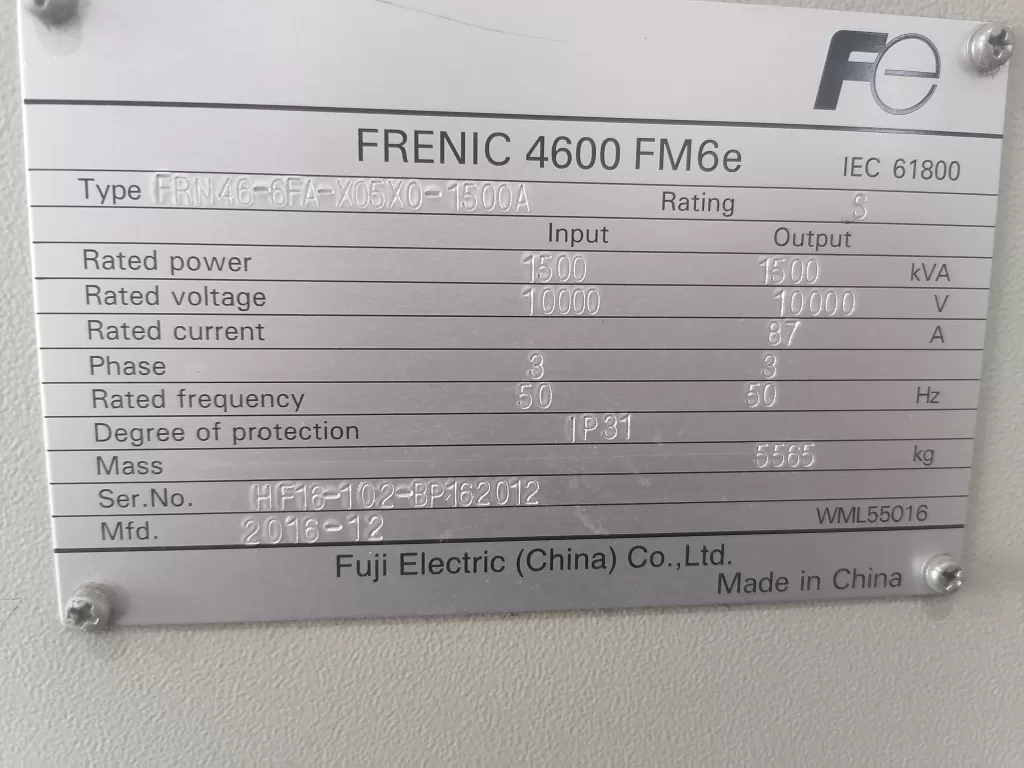
The Fuji FRENIC 4600 series high-voltage inverters are widely used in industrial drive systems, playing a vital role in driving large power equipment due to their stable performance and efficient control capabilities. However, after long-term use or idle periods, inverters may experience some faults, particularly in cases of electrical connection issues or abnormal motor loads. Common faults include PWM fiber optic connection errors and motor overload alarms. These faults are often interrelated, and it is necessary to perform a thorough analysis to determine the root cause of the failures and take corrective actions.

This article will analyze the relationship between PWM fiber optic connection errors and motor overload faults, explore the fundamental causes behind these issues, and propose targeted solutions based on systematic troubleshooting methods.

FRENIC 4600 FM6e

1. Causes and Analysis of PWM Fiber Optic Connection Errors

1.1 Fiber Optic Connection Issues

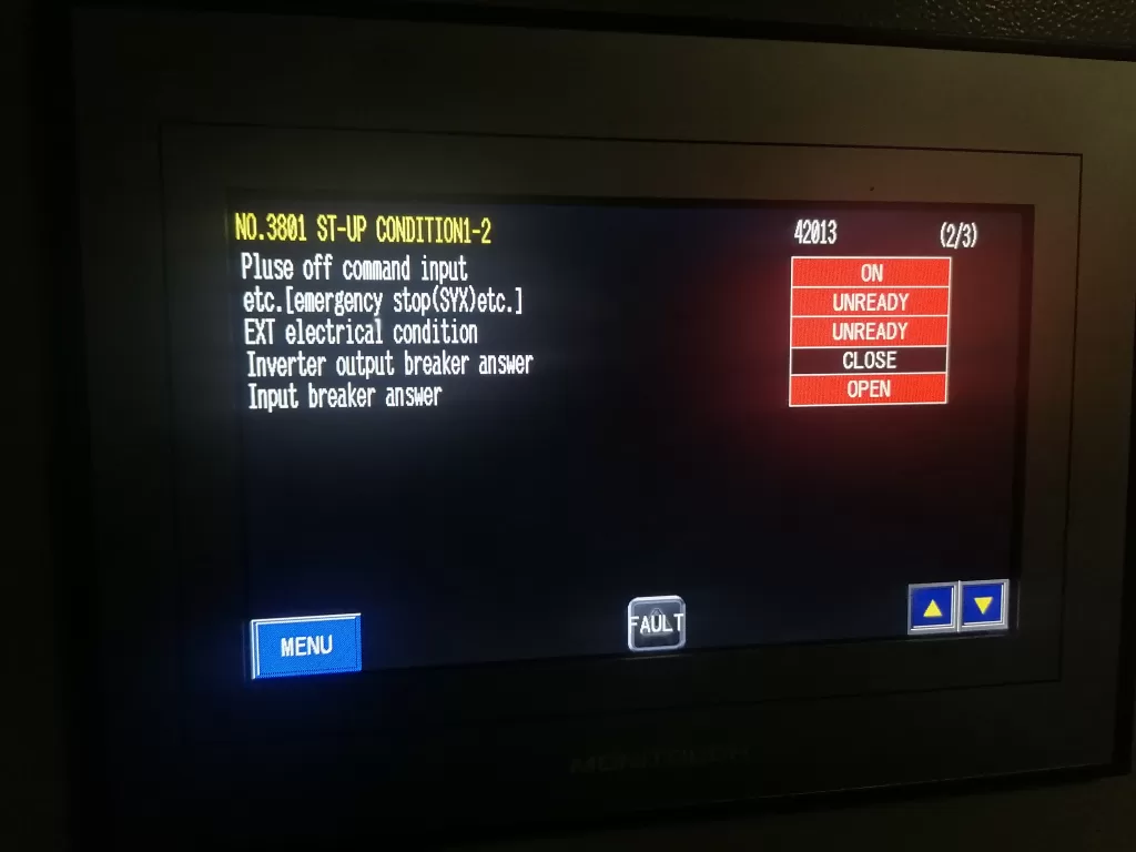
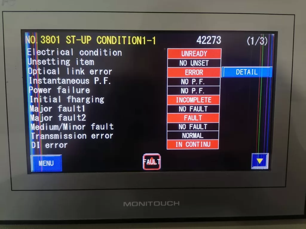
PWM (Pulse Width Modulation) fiber optic connections are a critical path for signal transmission between the inverter’s internal control system and external devices. When there is instability or loss of the fiber optic connection, the inverter may fail to receive or transmit control signals correctly. Common fiber optic connection issues include:

  • Loose or Damaged Fiber Optic Connectors: Over time, after prolonged use or idle periods, the fiber optic connectors may become loose, oxidized, or physically damaged, resulting in unstable signal transmission.
  • Pollution or Obstruction of Fiber Optic Connectors: Dust, oil, and other substances can accumulate on fiber optic connectors, impacting the quality of signal transmission, which may lead to connection errors.
  • Electromagnetic Interference (EMI): In environments with strong electromagnetic interference, signals can be disrupted, causing errors in fiber optic communication.

When these issues occur, the inverter’s signal transmission is interrupted or distorted, preventing the control system from regulating the motor’s operation properly.

Inverter output breaker answer

1.2 Triggering Mechanism of Motor Overload

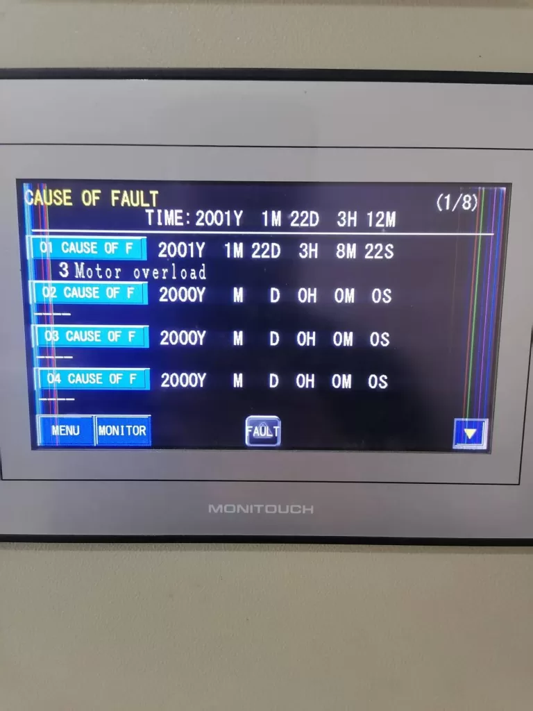
When a fiber optic connection error occurs, the inverter may fail to obtain accurate motor status information or adjust the output frequency correctly. Without proper regulation of the motor load and operating conditions, the inverter may generate unstable power or current output, resulting in motor overload.

  • Loss of Control Signals: With a fiber optic connection error, the inverter cannot receive feedback from the motor, leading to an inability to regulate the motor’s load properly, which causes excessive current and triggers the overload alarm.
  • Frequency Regulation Failure: If the inverter cannot correctly adjust the output frequency due to fiber optic signal loss, the motor may run at non-optimal settings for extended periods, leading to overload.
  • Excessive Inrush Current During Startup: Without proper communication through fiber optic signals, the inverter may fail to handle the large inrush current during motor startup, resulting in an overload fault.

2. Correlation Between Fiber Optic Connection Errors and Motor Overload

From the fault diagnosis experience, PWM fiber optic connection errors and motor overload are closely related. Fiber optic connection errors typically serve as the root cause, while motor overload is a direct consequence of this issue.

  1. Protection Mechanism Triggered by Signal Loss: If the inverter cannot obtain motor feedback due to a fiber optic connection issue, the system may enter a “protection mode” and activate overload protection. This prevents the system from operating normally, resulting in excessive current flowing through the motor and triggering an overload alarm.
  2. Incorrect Motor Load Detection: Without proper fiber optic feedback, the inverter may misinterpret the motor load, causing the system to falsely detect an overload condition and activate the protection mechanism unnecessarily.
Motor overload

3. Fault Analysis and Troubleshooting Steps

3.1 Power Off and Reset

Since a fiber optic connection issue can trigger the inverter’s internal protection mechanism, the first step is to perform a power off and reset operation. Disconnect the power, ensuring the system is completely powered off, then execute the inverter’s reset procedure to clear all alarm information.

3.2 Inspect Fiber Optic Connections

After the reset, the next step is to inspect the PWM fiber optic connections for any issues such as looseness, damage, or contamination. Prolonged use or idle periods may cause degradation in fiber optic connectors. Follow these steps to check the fiber optic connections:

  • Check the Connectors and Cables: Ensure that the fiber optic connectors are secure, free from oxidation, and that the cables are not damaged or broken.
  • Clean the Fiber Optic Connectors: Use cleaning tools to remove any dust or oil contaminants from the fiber optic connectors to ensure proper signal transmission.
  • Replace Fiber Optic Cables: If the fiber optic cables are damaged, they should be replaced immediately.

3.3 Inspect the Motor and Load

Once the fiber optic connection issue is resolved, inspect the motor and load for potential faults. Motor overload may also be caused by mechanical issues with the motor or abnormal load conditions. Check the motor’s condition and verify that the load is within normal operating limits:

  • Check the Motor Condition: Use a multimeter to test the motor’s winding resistance to ensure there are no short circuits or grounding faults.
  • Check the Load Equipment: Ensure that the load connected to the motor is not too heavy or jammed. Examine the mechanical components for signs of resistance or abnormal wear.

3.4 Check Inverter Control Parameters

If no issues are found with the motor or load, the next step is to check the inverter’s control parameters. Ensure that the overload protection and current limit settings on the inverter are correct and aligned with the motor’s rated specifications:

  • Adjust Overload Protection Settings: Modify the inverter’s overload protection parameters according to the motor’s rated power and load requirements to avoid overly sensitive triggering of the protection mechanism.
  • Set Frequency Limits: Verify that the inverter’s frequency settings are within the motor’s maximum operating frequency range to prevent overload conditions caused by excessive frequency.

3.5 Inspect Current Detection Circuit

Finally, check the inverter’s current detection circuit for functionality. A faulty current sensor or circuit could lead to incorrect readings, resulting in false overload alarms. Use the inverter’s diagnostic functions to inspect the current sensor and replace or repair it as needed.

Optical link error

4. Conclusion

The PWM fiber optic connection error and motor overload fault in the Fuji FRENIC 4600 series inverter are often interrelated, with the fiber optic connection issue serving as the root cause and the motor overload being a direct consequence. Fiber optic connection errors result in signal loss, which prevents the inverter from properly regulating the motor load and frequency, triggering an overload alarm. By systematically checking fiber optic connections, motor conditions, inverter parameters, and current detection circuits, these faults can be resolved, and the system can return to normal operation. Throughout the troubleshooting process, it is essential to prioritize high-voltage safety and follow proper electrical safety protocols to ensure the safety of both the equipment and personnel.

Posted on

Fuji Frequency Converter FRENIC-Multi (FRN E1S) Series User Manual Guide

I. Introduction to the Operation Panel Functionality and Key Parameter Settings

1.1 Introduction to the Operation Panel Functionality

Fuji frequency converter E1S series operation panel function diagram

The Fuji Frequency Converter FRENIC-Multi (FRN E1S) series features an intuitive operation panel that allows users to easily monitor and control the operation of the frequency converter. The operation panel provides various functions such as setting operating frequencies, monitoring operating status, and configuring parameters.

Key Features of the Operation Panel:

  • LED Display: Displays various operating parameters such as output frequency, output current, and operating status.
  • UP/DOWN Keys: Used to adjust the set frequency.
  • RUN/STOP Keys: Used to start and stop the motor.
  • Mode Selection Keys: Allows switching between operation modes such as run mode, program mode, and alarm mode.

1.2 Setting the Electronic Thermal Relay Function

The electronic thermal relay function protects the motor from overheating by monitoring the output current of the frequency converter. To configure this function, the following parameters need to be set:

  • F10 (Thermal Relay Characteristic Selection): Selects the cooling system characteristic of the motor. Options include self-cooled motors with built-in fans and externally cooled motors.
  • F11 (Thermal Relay Action Value): Sets the current level at which the thermal relay will trip. This value should typically be set to around 100-110% of the motor’s rated current.
  • F12 (Thermal Time Constant): Sets the time it takes for the thermal relay to trip after the current exceeds the action value. This value depends on the motor’s thermal properties and the ambient operating conditions.

1.3 Configuring the Instantaneous Power Failure Restart Function

The instantaneous power failure restart function allows the frequency converter to automatically restart the motor after a temporary power outage. To enable and configure this function, the following parameters need to be set:

  • F14 (Instantaneous Power Failure Restart Selection): Enables or disables the instantaneous power failure restart function. Options include no restart (instant trip), no restart with reset on power restoration, restart at the frequency at the time of power failure (for general loads), and restart at the start frequency (for low-inertia loads).
  • H13 (Restart Waiting Time): Sets the time to wait after detecting a power failure before attempting to restart the motor. This helps to ensure that the residual voltage in the motor windings has decayed sufficiently to prevent inrush currents.
  • H14 (Frequency Ramp-Down Rate): Sets the rate at which the output frequency is reduced during restart to synchronize with the motor’s rotational speed and prevent excessive currents.
  • H16 (Instantaneous Power Failure Allowable Time): Sets the maximum time that can elapse after a power failure before the restart function is disabled.
Fuji frequency converter E1S standard wiring diagram

1.4 Selecting and Configuring the Terminal FM Function

The terminal FM provides an analog output signal that can be used to monitor various operating parameters of the frequency converter. To select and configure this function, the following steps are required:

  • F29 (Terminal FM Action Selection): Selects whether the terminal FM outputs a voltage signal (0-10V) or a pulse signal.
  • F30 (Output Gain): Adjusts the gain of the analog output signal. This allows scaling the output signal to match the input range of the monitoring equipment.
  • F31 (Function Selection): Selects the parameter to be monitored and output through the terminal FM. Options include output frequency, output current, output voltage, motor torque, load rate, and more.
  • F33 (Pulse Rate): When pulse output is selected, this parameter sets the pulse rate at 100% output.

By carefully configuring these parameters, users can fully utilize the advanced functionality of the Fuji FRENIC-Multi (FRN E1S) series frequency converter to optimize motor control and protect against potential faults.

Posted on

Fuji Inverter FRENIC 5000 G11S/P11S Series User Manual Guide

I. Operation Panel Function Introduction

The operation panel of the Fuji INVERTER FRENIC 5000 G11S/P11S series is the primary interface for user interaction with the frequency converter. It is equipped with a series of buttons and an LED display for setting parameters, monitoring operating status, and executing control operations.

Fuji FRENIC5000G11SP11S KEYPAD PANEL

1.1 Button Functions

  • FWD/REV Keys: Used to start the frequency converter, enabling the motor to rotate forwards or backwards.
  • STOP Key: Used to stop the frequency converter.
  • ∨ or ∨ Keys: In program mode, these keys are used to vertically move the cursor to select function codes or data.
  • FUNC DATA Key: In program mode, this key is used to store modified data or switch display screens.
  • RESET Key: In program mode, this key is used to cancel the current input data; in fault mode, it is used to release the fault stop status.
  • PRG Key: Used to switch between operation mode and program mode.
  • SHIFT Key (Column Shift): In program mode, when used in combination with the ∨ or ∨ keys, it moves the cursor horizontally.

1.2 Restoring Factory Default Parameter Settings

To restore factory default parameter settings, follow these steps:

  1. Press the PRG key to enter program mode.
  2. Use the ∨ or ∨ keys to select “1. DATA SET”.
  3. Press the FUNC DATA key to confirm the selection.
  4. Simultaneously press the STOP key and the ∨ key to change the parameter protection value from “1” to “0”, allowing parameter modifications.
  5. Again, use the ∨ or ∨ keys to select “F00 Data protection” and set its value to “0”.
  6. Press the FUNC DATA key to save the settings. The frequency converter will restart and restore the factory default parameters.

1.3 Setting and Clearing Passwords

The Fuji FRENIC G11S/P11S series provides password protection to restrict access to parameters. However, the specific methods for setting and clearing passwords are not detailed in the provided manual. Typically, such functions may require setting through specific parameter codes, and the unlocking process may involve the manufacturer or authorized service personnel. It is recommended to refer to Fuji’s official technical support documentation or contact the manufacturer for detailed guidance.

Fuji FRENIC5000 G11S/G9S Inverter wiring-diagraml

II. Terminal Start/Stop and Potentiometer Speed Regulation

2.1 Terminal Start/Stop

The Fuji FRENIC G11S/P11S series supports start/stop control via external terminals. To achieve this, relevant parameters need to be set correctly, and wiring must be done accordingly:

  • Parameter Setting: Set function code F02 to “1” to select external signal input mode.
  • Wiring: Connect the control power to terminals R0 and T0; connect the start signal (e.g., FWD) to the corresponding digital input terminal (e.g., X1); connect the stop signal to the REST terminal.

2.2 Potentiometer Speed Regulation

Potentiometer speed regulation is a method of changing the frequency output by adjusting the resistance value of an external potentiometer. The setup steps are as follows:

  • Parameter Setting: Set function code F01 to “1” to select voltage input mode.
  • Wiring: Connect the output terminal of the potentiometer to the frequency setting terminal of the frequency converter (e.g., terminal 12), and simultaneously ground the common terminal of the potentiometer (e.g., 0V terminal).

III. Frequency Converter Fault Code Analysis and Solutions

When the Fuji FRENIC G11S/P11S series encounters a fault, it will display the corresponding error code, helping users quickly locate the problem. The following are some common fault codes, their analyses, and solutions:

  • OC1: Overcurrent during acceleration. Possible causes include motor blockage, excessive load, or improper parameter settings. Solutions include checking the motor and load status, and adjusting acceleration time and current limit parameters.
  • OU: DC bus overvoltage. Possible causes include braking resistor failure, excessively short deceleration time, or abnormal supply voltage. Solutions include checking the braking resistor and wiring, and adjusting deceleration time and voltage limit parameters.
  • OL: Electronic thermal relay overload. Possible causes include motor overload, poor heat dissipation, or improper parameter settings. Solutions include checking the motor load and heat dissipation conditions, and adjusting the overload protection parameters.
  • Er1: Memory error. Possible causes include internal frequency converter faults or program abnormalities. Solutions include restarting the frequency converter; if the problem persists, contact the manufacturer for repair.

Summary

The Fuji Inverter FRENIC 5000 G11S/P11S series user manual provides detailed operation guides and parameter setting instructions, helping users fully utilize the various functions of the frequency converter. Through this guide, users can understand the functions of the operation panel, the method for restoring factory default parameter settings, the setup steps for terminal start/stop and potentiometer speed regulation, as well as the analysis and solutions for common fault codes. This information is crucial for ensuring the normal operation and efficient use of the frequency converter.