Posted on

Deep Dive into Allen-Bradley PowerFlex 400 Fault 032: From Internal Logic to Advanced Maintenance Strategies

Introduction: The Guardian of Thermal Management

In the landscape of industrial automation, the Allen-Bradley PowerFlex 400 AC drive is a staple for Fan & Pump applications, optimized for HVAC, water treatment, and building automation. In these critical environments, system stability is not just about energy efficiency—it is a cornerstone of operational safety.

Among the various diagnostic codes, Fault 032 (F032) is one of the most significant yet misunderstood signals. It is more than a simple error; it is an urgent “SOS” from the drive’s thermal management system. This article provides a comprehensive analysis of the F032 fault, covering its underlying mechanisms, diagnostic logic, and a full-spectrum solution for maintenance engineers.
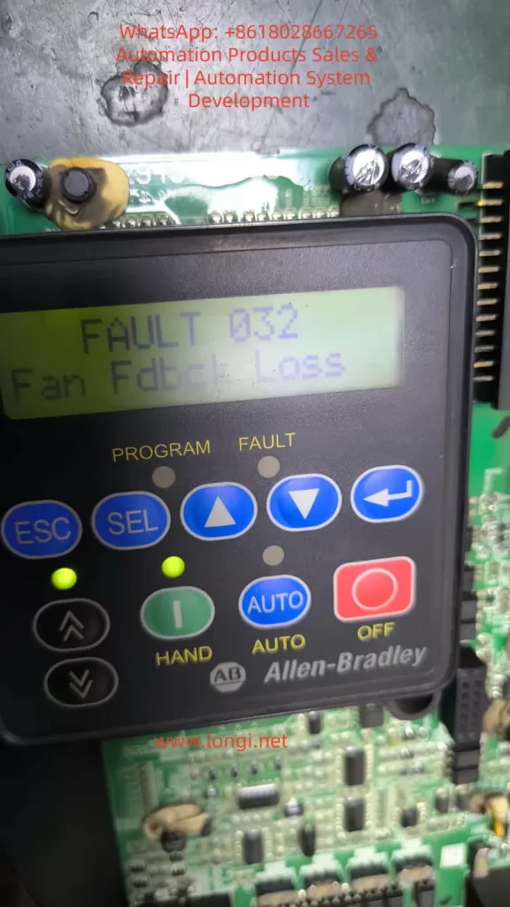

fault 032 fan fdbck loss

Chapter 1: Decoding F032 – The Critical Role of Fan Feedback

1.1 Defining the Fault

According to the PowerFlex 400 User Manual, F032 stands for “Fan Fdbck Loss.” This indicates that the drive has detected an inconsistency between the commanded state of the cooling fan and the actual speed feedback received by the control board.

This fault is specific to higher-power units, particularly those in Frame D and Frame E sizes. Unlike smaller drives that use simple “always-on” fans, these larger frames utilize a closed-loop monitoring system. The drive provides power to the fan and monitors a dedicated feedback line (usually a Hall-effect sensor signal) to verify rotation. If the drive expects the fan to spin but detects no pulses, it triggers an F032 trip to prevent the catastrophic failure of power components like IGBTs.

1.2 Why Only Large Frames?

Smaller units (Frame C) often rely on simpler cooling structures or auxiliary fans without feedback. However, Frames D and E integrate high-density power modules that generate significant heat. These frames require high-performance feedback-controlled fans to ensure cooling redundancy and safety.


Chapter 2: The Physical Logic of Thermal Management

2.1 The Enemy of Semiconductors: Heat

The core of the drive is the IGBT (Insulated Gate Bipolar Transistor). During high-speed switching, IGBTs generate substantial thermal energy through switching and conduction losses. If the heatsink’s heat is not extracted by the fan, the junction temperature rises rapidly. Exceeding the critical limit (typically 125°C–150°C) results in irreversible physical damage to the semiconductor structure.

2.2 Framework and Airflow Design

PowerFlex 400 is categorized by Frame Sizes to simplify maintenance.

  • Frame D & E: These models feature powerful cooling fans located at the top or bottom. Their internal air ducts are designed for high-velocity vertical airflow, making the fan the single most critical component for hardware longevity.

Chapter 3: Multi-Dimensional Root Cause Analysis

When F032 appears, an engineer must use a “layered” diagnostic approach, moving from physical to electrical causes.

3.1 Physical Layer: Obstruction and Wear

  • Mechanical Blockage: Cotton lint, dust buildup, or debris (like stray cable ties) can physically jam the fan blades.
  • Bearing Failure: In high-temperature environments, bearing grease can dry out or carbonize, leading to increased friction, reduced speed, or a total seize-up of the motor.

3.2 Electrical Layer: Connections and Signals

  • Loose Connectors: Constant micro-vibrations in industrial settings can cause the fan’s plug to drift from the control board socket.
  • Feedback Circuit Failure: The internal Hall sensor within the fan may fail. In this case, the fan might physically spin, but the drive “sees” no speed pulses.
  • Power Supply Issues: The Switched-Mode Power Supply (SMPS) providing 24V DC to the fan may experience voltage drops or failure.

3.3 Environmental Layer: Installation Layout

If the drive is installed in a space with insufficient clearance, backpressure increases. This forces the fan to work harder, potentially leading to speed fluctuations that trigger the feedback loss fault.
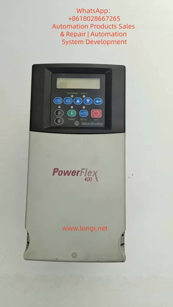

powerflex 400

Chapter 4: Step-by-Step Diagnostic and Troubleshooting

Safety Warning: Before any disassembly, disconnect all power and wait at least 3 minutes for the bus capacitors to discharge to safe levels.

Step 1: Preliminary Visual and Manual Inspection

  1. Isolate Power: Lock out and tag out the input power.
  2. Access the Fan:
    • Frame D: Loosen the two cover screws and pull the cover bottom out and up.
    • Frame E: Loosen the four cover screws and pull the cover out and up.
  3. Manual Rotation: Spin the fan blades by hand. They should move freely. If you feel resistance or hear grinding, the fan must be replaced.

Step 2: Connection Integrity Check

  1. Locate the fan’s wiring harness connected to the main control board.
  2. Unplug the connector and inspect the pins for oxidation, corrosion, or burning.
  3. Reseat the connector firmly until it clicks into place.

Step 3: Voltage Measurement

  1. With the drive safely energized (following proper safety protocols), measure the DC voltage at the fan power terminals.
  2. A healthy PowerFlex 400 should provide a steady 24V DC.
  3. If 24V is present but the fan does not spin, the fan motor is defective.

Step 4: Pulse Signal Testing (Advanced)

Using an oscilloscope, you can probe the feedback line. A functional fan will produce a continuous square wave signal while spinning. A flat line (high or low) indicates a failed Hall sensor.


Chapter 5: Component Replacement and System Reset

5.1 Replacement Essentials

If the fan is confirmed faulty, it must be replaced with an identical OEM specification part. Pay close attention to airflow direction (usually indicated by an arrow on the fan housing). Installing the fan backward will cause heat to build up, leading to an immediate over-temperature trip.

5.2 Clearing the Fault

Once the hardware issue is resolved, reset the drive via:

  1. HIM Keypad: Press the Stop/Reset key.
  2. Power Cycle: Turn off the input power completely and restart.
  3. Parameter Reset: Set Parameter A197 [Fault Clear] to 1 or 2.
  4. Auto-Restart: If appropriate for your application, adjust A163 [Auto Rstrt Tries] and A164 [Auto Rstrt Delay].

Chapter 6: Preventative Maintenance Strategies

6.1 Environmental Optimization

  • Dust Mitigation: Regular cleaning of the drive’s air intake is the best way to protect the fan.
  • Ambient Control: Ensure the air temperature stays within the -10°C to 45°C range. In harsh environments, consider a NEMA 12 enclosure with filtered ventilation.

6.2 Lifecycle Management

Cooling fans are consumable parts. Following industry guidelines for solid-state controllers, it is recommended to proactively replace fans every 3 to 5 years, depending on the duty cycle and environment.


Conclusion

Fault 032 is a vital protective logic that ensures the longevity of your PowerFlex 400. By understanding the relationship between the physical rotation of the fan and the electronic feedback expected by the drive, engineers can move beyond “guessing” and implement precise, logical repairs. Regular maintenance and environmental awareness are the keys to ensuring your drive—and your facility—stays cool and operational.
Posted on

Root Cause Analysis and System-Level Repair Approaches for DSC Q100 Startup Failure: An Engineering Perspective from Power Fluctuations to Storage Media Damage

I. Problem Background: DSC Q100 Startup Failure Is Not a “Minor Software Glitch”

The TA Instruments DSC Q100 is a widely used differential scanning calorimeter. During long-term operation, under unstable laboratory power supply conditions, or due to equipment aging, some users may encounter issues such as the instrument getting stuck on the startup screen after power-on, the system being unable to enter the operation interface, and repeated power cycling and restarts being ineffective. Upon disassembling the instrument, a small-capacity storage card is found inside, and this card cannot be read or have files copied from it when inserted into a regular computer. Such problems are not simple software failures but rather typical cases of “embedded system boot media failure.”

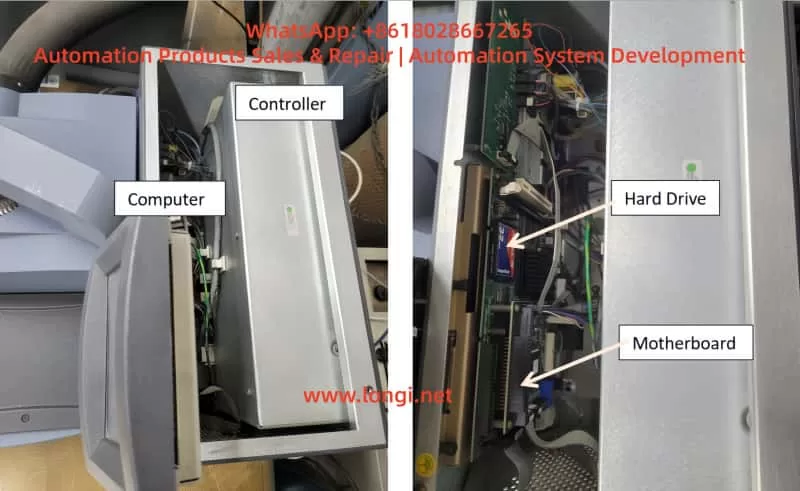
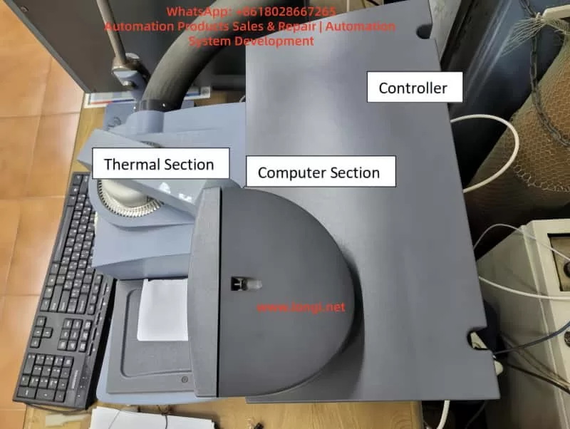
Appearance drawing of DSQ 100

II. DSC Q100 System Architecture: It Is Essentially an “Industrial Embedded Computer”

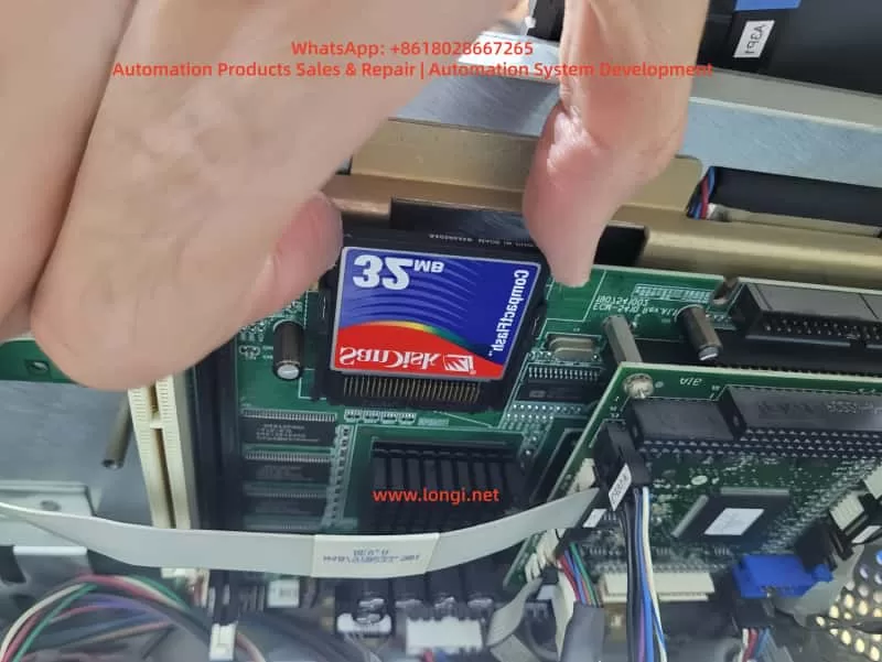
The DSC Q100 contains a complete embedded computer system internally. Its basic components include an industrial motherboard, a CPU/chipset, RAM, a small-capacity storage medium (commonly CompactFlash, DOM, or industrial Flash cards), an operating system (mostly customized Windows Embedded or a dedicated embedded OS), and TA Instruments-specific drivers and applications. The storage card, around 32 MB in size, serves as the system boot disk, containing the boot sector, core operating system files, instrument drivers, configuration files, and some calibration and identification information. Once it cannot be read, the system startup will be interrupted.

III. Phenomenon Analysis: Why Can’t the Computer Read This Card?

Since the storage card cannot be normally opened or have files copied from it when inserted into a regular computer, we can rule out instrument software bugs, upper computer software issues, and simple parameter configuration errors. The fault is thus concentrated on the failure of the boot storage medium itself. The following is a comparative analysis of three possibilities:

SituationLikelihoodEngineering Judgment
The computer cannot detect the device at allHighHardware damage to the storage card / controller damage
The device is detected but prompts “RAW” or “unformatted”HighFile system damage
Abnormal recognition and capacity errorsMediumExcessive bad blocks / controller abnormalities
The computer can read it normallyLowInstrument motherboard or interface issues

IV. Root Cause: Power Fluctuations Are the “Silent Killer”

The customer mentioned power fluctuations in their description, which is an underestimated yet highly destructive factor in the maintenance of analytical instruments. The reasons why power fluctuations can damage the storage card are as follows:

  • Voltage fluctuations during the writing process
  • Interruption of an incomplete write operation
  • Damage to file system metadata
  • A rapid increase in Flash bad blocks
  • The controller entering an abnormal state

The risks are highest in scenarios such as laboratories without an uninterruptible power supply (UPS), the start-up and shutdown of high-power equipment on the same power circuit, poor mains quality, and long-term operation of the instrument. The result may be that the system can still power on once but fails to start up the next time.

Memory card for DSC Q100

V. Why “Copying Files from Another DSC” Often Doesn’t Work

Customers may consider copying files from another DSC Q100 to a new card, but this method has a low success rate for the following reasons:

  • Startup doesn’t rely solely on “files”: System startup also involves the master boot record (MBR)/boot sector, hidden partitions, specific disk geometries, write timing, and alignment, which cannot be restored through ordinary file copying.
  • Possible machine-specific information: Some instruments store device serial numbers, configuration fingerprints, and calibration-related information on the system disk. Simple copying may lead to abnormal system startup, software errors, and limited functionality.
  • The correct engineering approach is “whole-disk cloning”: If another device must be used as a reference, the only reliable method is to create a “sector-by-sector image” of the complete storage card and then write it to the new card, rather than copying folders.

VI. Recommended Engineering-Grade Handling Process (Practical-Oriented)

  • Step 1: Immediately stop repeated power cycling: Avoid further damage to the storage medium.
  • Step 2: Confirm the storage card type: Determine whether it is a CF, DOM, or other industrial card, use the correct card reader, and avoid misjudgment due to SD adapters.
  • Step 3: Create a “whole-disk image” as soon as the card is recognized: This is the core step for data rescue and system recovery. The principle is to image first and then repair; operate only on the image, not on the original card.
  • Step 4: Prioritize obtaining system recovery media from the original manufacturer or agent: This is the method with the highest success rate and the lowest risk.
  • Step 5: Ensure hardware and software version consistency if using a cloning solution: This includes matching the motherboard version, software version, and model.
  • Step 6: Address power issues after repair: Otherwise, all efforts may be in vain in the event of another voltage fluctuation.

VII. Preventive Measures: More Important Than Repair

  • Install an online UPS: It should have voltage stabilization, filtering, and transient interruption protection functions.
  • Check the grounding and power supply circuit: Avoid interference from inductive loads.
  • Proactively replace the storage medium for aging equipment: The original storage cards in DSC Q100 instruments that have been in operation for many years are approaching the end of their service life. Proactively replacing them with industrial-grade new cards is a preventive maintenance measure.
Internal physical diagram of DSQ 100

VIII. Conclusion: This Is a Typical “System Engineering Problem,” Not an Accidental Failure

The DSC Q100 startup failure case clearly shows that high-end analytical instruments are not maintenance-free electronic devices. The stability of embedded systems is highly dependent on power quality, and the storage medium is a “hidden key weak point.” The correct maintenance approach requires a system engineering perspective. True professional maintenance and technical support do not involve repeatedly reinstalling software but rather understanding the system, respecting the hardware, controlling risks, and eliminating root causes.

Posted on

In-Depth Technical Analysis and Engineering Handling Guide for SINAMICS G120 Alarm F30005 (Power Unit Overload)

I. Fault Background and Positioning Principles

In the Siemens SINAMICS G120 series variable frequency drive system, the fault code F30005 – Power unit overload falls within the range of 30000–30999 and is clearly attributed to the DRIVE-CLiQ power unit (Power Module, PM) itself, rather than the control unit (CU) or the external communication layer. This fault code indicates that the power module has internally determined that its operating state has exceeded the safe operating boundaries, and does not simply refer to motor overload or a load current exceeding the nameplate value.

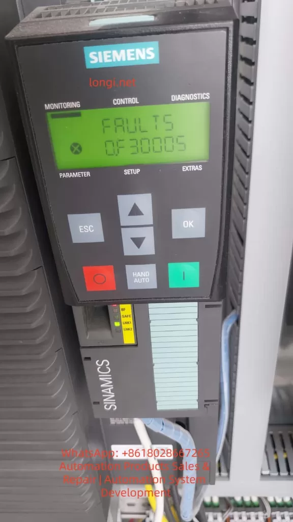
faults 0.F30005

II. The True Meaning of “Power Unit Overload” in SINAMICS G120

1. Siemens’ Engineering Definition of “Overload”

In the SINAMICS system, “Power Unit Overload” is not a simple I²t overload protection but the result of a multi-dimensional comprehensive assessment, including power device (IGBT) junction temperature models, heat sink temperature rise models, output current time integrals (equivalent thermal loads), abnormal DC bus energy flows, and the coupling effects of switching losses and carrier frequencies. F30005 is the final outcome of a thermal model mismatch or stress overrun in the power module.

2. Relationship with the F3xxxx Coding System

The range 30000–30999 clearly points to the DRIVE-CLiQ power unit, with F30005 being a typical representative within this range. This means that the fault source lies in power modules such as the PM240/PM240-2/PM250, with the CU only responsible for forwarding the fault information. DRIVE-CLiQ communication serves as an information channel and is not the root cause of the fault.

III. Typical Trigger Scenarios for F30005

Scenario 1: Long-Term Operation in the “Hidden Overload Zone” of the Power Module

The operating current does not exceed the rated value, but prolonged operation, high ambient temperatures, and inadequate cabinet ventilation design lead to continuous accumulation in the IGBT junction temperature model, ultimately triggering F30005. This is a thermal design issue, not a parameter issue.

Scenario 2: Low-Speed, High-Torque Operating Conditions

In low-frequency (<10 Hz), high-torque maintenance, vector control/DTC modes, prolonged “holding still” results in a significant increase in IGBT conduction losses, reduced fan speed, decreased cooling capacity, and a thermal model accumulation rate that far exceeds expectations.

Scenario 3: Improper Matching Between the Power Module and the Motor

If the PM power selection is too small, the motor’s rated current is close to the PM’s upper limit, the actual load torque exceeds the design value, or high-inertia mechanical systems are used, the power module will alarm even if the parameters “appear to be fine.”

Scenario 4: Improper Carrier Frequency Settings

Setting the carrier frequency too high (e.g., 8–12 kHz) in pursuit of low noise, combined with high power, leads to increased IGBT switching losses, rising module heat generation, and ultimately triggers F30005.

IV. Why “Restarting Works for a While,” but the Fault Recurs?

The thermal model is reset upon power-off, and the actual IGBT junction temperature drops, temporarily restoring the system’s “safety margin.” However, as long as the operating conditions, cooling conditions, and parameters remain unchanged, the thermal model will accumulate again, and the fault will inevitably reoccur.

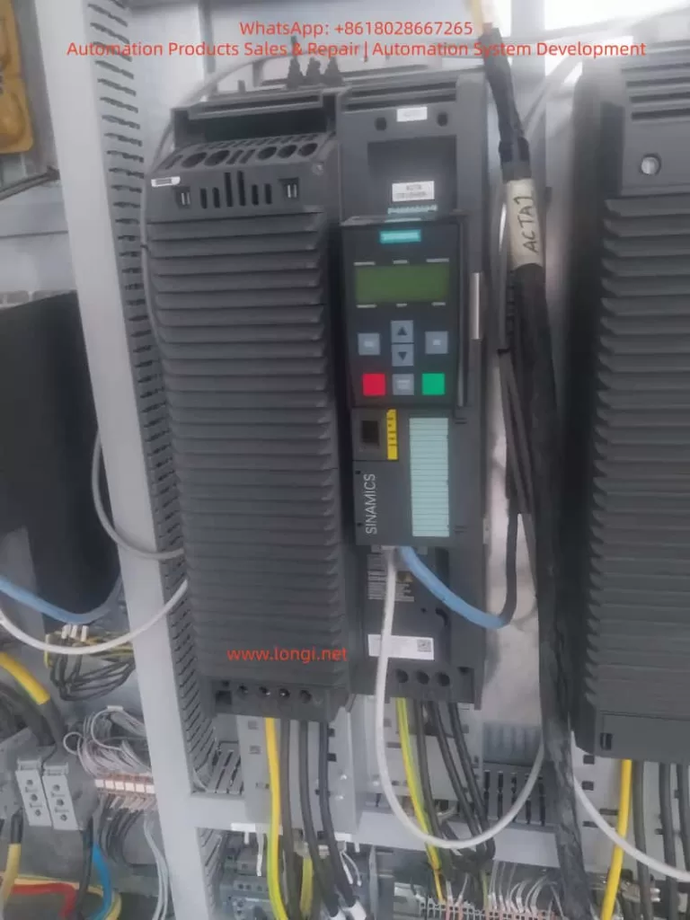
G120 drive

V. The Fundamental Differences Between F30005 and “Motor Overload”

Comparison ItemMotor OverloadF30005
Monitoring ObjectMotorPower Module
Judgment BasisCurrent/I²tThermal Model + Energy
Must Have High CurrentYesNot Necessarily
Short-Term RecoverabilityLimitedObvious
Root CauseMechanical or LoadElectrical + Thermal

VI. Engineering-Level Troubleshooting Process

Step 1: Confirm the Power Module Model and Rated Capacity

Check the model and current rating of power modules such as the PM240/PM240-2/PM250 to confirm whether they are operating close to or exceeding 80% of their long-term capacity. Insufficient power module selection is a common cause.

Step 2: Inspect Cabinet Cooling and Environmental Conditions

Focus on the cabinet temperature, whether the air duct is blocked by cables, and whether the PM fan is aged or dusty.

Step 3: Analyze Operating Conditions

Confirm whether there is long-term low-speed, heavy-load operation, frequent starting/stopping, or accumulation of DC braking or regenerative energy.

Step 4: Review Carrier Frequency and Control Modes

Check whether thermal margins have been sacrificed for “quietness” and whether unnecessary high-performance control modes are being used.

VII. Sustainable Solutions

✔ Correct Approaches

  • Reduce the carrier frequency to decrease IGBT switching losses.
  • Optimize the process operating curve to avoid prolonged low-speed, heavy-load operation.
  • Improve cooling conditions, such as clearing air ducts and replacing aged fans.
  • Upgrade the power module rating if necessary to increase system redundancy.

✘ Incorrect Practices

  • Repeatedly resetting the system while ignoring the root cause.
  • Blindly increasing overload parameters to mask the fault.
  • Ignoring cabinet thermal design, leading to recurring issues.
  • Shifting the blame to the motor, delaying repair timing.

VIII. Conclusion: F30005 is the “Power Module’s Self-Preservation Mechanism”

F30005 is not bad news but a clear indication from the power module that the current system’s thermal-electrical-mechanical balance has been disrupted. Ignoring it may lead to permanent IGBT damage, drive failure, and costs far exceeding those of a reasonable rectification. Therefore, F30005 faults should be taken seriously, and timely troubleshooting and resolution should be carried out.

Posted on

In-Depth Analysis and Solution Guide for ERCON Communication Fault in HiMEC HI2xx Series Servo Drives

Introduction

Servo drives, as the core control components of industrial automation equipment, directly determine the operational efficiency and production continuity of devices. The HiMEC HI2xx series servo drives, renowned for their high cost performance and user-friendliness, are widely applied in machine tools, robots, packaging machinery, and other fields. However, in practical use, the ERCON fault (flashing display) caused by communication interruption between the operator (e.g., drive panel) and the main board is one of the most common issues. If unresolved promptly, it can lead to equipment downtime and production stagnation. This article delves into the root causes of the ERCON fault in HI2xx series drives, provides a step-by-step solution guide, and proposes preventive measures to help technicians quickly locate and resolve the problem.

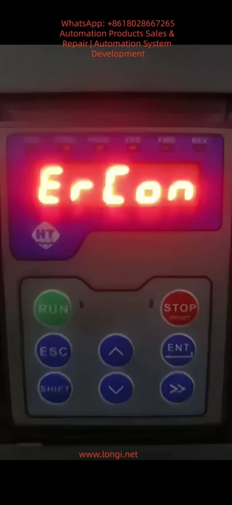
ercon fault

1. Overview of ERCON Fault

1.1 Fault Definition

ERCON (Error Communication) is a communication fault code specific to HiMEC HI2xx series drives, referring to the interruption of the communication link between the operator (e.g., drive panel, handheld programmer) and the main board. When the communication link is abnormal, the operator triggers a communication alarm and displays “ERCON” in a flashing manner, alerting users to check the communication system immediately.

1.2 Fault Impact

  • The operator cannot receive status information from the main board (e.g., motor speed, torque, alarm codes);
  • Control commands (e.g., start, stop, parameter modification) cannot be sent to the main board;
  • The drive enters protection mode, unable to drive the motor normally, and may cause equipment shutdown in severe cases.

2. In-Depth Analysis of Fault Causes

The communication link of HI2xx series drives consists of three parts: operator, communication cable, and main board interface (Figure 1). Any abnormality in these components can trigger the ERCON fault. Below is a detailed breakdown of the causes:

2.1 Communication Cable Fault (Most Common Cause)

The communication cable is the “signal bridge” connecting the operator and the main board, accounting for over 60% of ERCON faults. Specific causes include:

  • Physical damage: Internal conductors break due to long-term vibration or bending (e.g., copper foil fracture in a flat cable);
  • Loose connection: Poor contact between the plug and socket due to vibration or repeated插拔 (e.g., reduced clamping force between a pin header and socket);
  • Electromagnetic interference (EMI): The communication cable is not shielded or laid parallel to power cables (e.g., motor cables), causing EMI to disrupt communication (e.g., RS485 differential signals are submerged by noise);
  • Aging: The insulation layer of the communication cable ages due to high temperature or humidity, leading to short circuits or signal attenuation.

2.2 Interface Fault

The communication interfaces of the operator or main board are “nodes” in the link, accounting for about 30% of faults. Specific causes include:

  • Pin damage: Pins (e.g., pin header, DB9 interface pins) bend or break due to forced插拔 or vibration (e.g., a pin header pin is bent and cannot contact the socket);
  • Oxidation/contamination: Pins oxidize (e.g., copper pins turn black) or the interface is contaminated with dust/oil in humid/dusty environments, increasing contact resistance and blocking signal transmission;
  • Lock failure: The plug lock (e.g., flat cable clip) breaks due to aging, causing the plug to loosen and lose contact.

2.3 Equipment Itself Fault

Faults in the internal communication circuits of the operator or main board account for about 10% of cases. Specific causes include:

  • Operator fault: The operator’s communication chip (e.g., RS485 transceiver) is damaged, unable to send/receive signals;
  • Main board fault: The main board’s communication interface circuit (e.g., UART, RS485 circuit) fails (e.g., capacitor breakdown, resistor burnout), preventing signal processing;
  • Firmware incompatibility: Mismatched firmware versions between the operator and main board (e.g., the operator’s firmware is upgraded but incompatible with the old main board’s communication protocol) disrupt communication.

2.4 Environmental Factors

  • Excessive temperature: The operating environment exceeds the rated range (e.g., HI2xx series operates at 0–45°C), softening the communication cable’s insulation or loosening solder joints on interface pins;
  • High humidity: Ambient humidity exceeds 85%, accelerating pin oxidation or reducing the communication cable’s insulation resistance (e.g., insulation resistance drops from 10MΩ to <1MΩ, causing severe signal attenuation);
  • Vibration: Long-term operation in high-vibration environments (e.g., presses, vibration tables) loosens communication cable plugs or breaks internal conductors.
hilectro servo

3. Step-by-Step Solution Guide for ERCON Fault

The following steps follow the principle of “from simple to complex, from external to internal” to help technicians troubleshoot without盲目 disassembling the device.

3.1 Step 1: Power Off and Preliminary Inspection

Purpose: Ensure safety and avoid damaging the device during live operations;初步 locate the fault scope.
Details:

  1. Power off: Turn off the drive’s power switch (e.g., circuit breaker) and unplug the power cord. Wait 5 minutes to discharge the drive’s internal capacitors;
  2. Visual inspection:
    • Check the communication cable for obvious breaks, bends, or insulation damage (e.g., exposed copper foil in a flat cable);
    • Check the connection between the plug and socket for looseness (e.g., the flat cable plug is not fully inserted into the socket);
    • Check the operator and main board interfaces for dust or oil (e.g., black dust in the interface);
  3. Re-plug the communication cable:
    • Release the plug lock (e.g., flat cable clip) and slowly pull out the plug;
    • Check the plug pins for bending or breakage (e.g., a pin header pin is bent);
    • Brush dust from the plug and socket with a brush, then reinsert the plug and ensure the lock is fastened (e.g., the flat cable clip is fully locked).

Notes:

  • Align the pins when plugging/unplugging to avoid bending pins with force;
  • Replace the communication cable if the plug lock fails (avoid using tape, which can cause poor contact).

3.2 Step 2: Continuity Test of Communication Cable

Purpose: Verify if the communication cable has internal breaks and eliminate conductor faults.
Details:

  1. Prepare tools: Multimeter (set to “continuity mode” or “resistance mode”);
  2. Test method:
    • Connect both ends of the communication cable to the operator and main board interfaces (e.g., insert both ends of the flat cable into the operator and main board sockets);
    • Touch the corresponding pins of the communication cable with multimeter probes (e.g., pin 1 to pin 1, pin 2 to pin 2, etc.);
    • If the multimeter shows “continuity” (resistance <1Ω), the conductor is normal; if it shows “open circuit” (infinite resistance), the conductor is broken.

Example:

  • If pin 3 of the communication cable is not continuous to pin 3, the 3rd conductor is broken and the cable needs replacement.

Notes:

  • Ensure both ends of the communication cable are not connected to the operator or main board during testing (to avoid interference from the main board circuit);
  • If the communication cable is a shielded type, test the shield continuity (the shield must be grounded to avoid EMI).

3.3 Step 3: Interface Inspection and Cleaning

Purpose: Eliminate poor contact caused by pin damage, oxidation, or contamination.
Details:

  1. Inspect pins:
    • Use a magnifying glass to check interface pins (e.g., socket pins): look for bending or breakage (e.g., a socket pin is bent);
    • If a pin is bent, slowly adjust it to vertical with tweezers (avoid excessive force to prevent breakage);
    • If a pin is broken, replace the interface (e.g., socket) or main board (if the pin is soldered to the main board).
  2. Clean oxidation and dust:
    • Soak a cotton swab in anhydrous alcohol (≥99% concentration) and wipe the interface pins (e.g., socket pins, plug pins);
    • Brush dust from the interface with a brush;
    • Reinsert the communication cable after the alcohol evaporates.

Notes:

  • Do not grind pins with sandpaper (this damages the pin coating and accelerates oxidation);
  • Use anhydrous alcohol to clean oil stains (avoid corrosive solvents like gasoline or thinner).

3.4 Step 4: Replace the Communication Cable

Purpose: Eliminate faults caused by the communication cable itself (e.g., internal breaks, aging).
Details:

  1. Select the communication cable:
    • Use a HiMEC original communication cable (matching the HI2xx series drive model, e.g., HI2-CABLE-01);
    • If an original cable is unavailable, use a shielded communication cable of the same specification (e.g., RS485 communication cables must be twisted-pair with a shield, and the shield must be grounded).
  2. Replacement method:
    • Disconnect both ends of the old communication cable (operator and main board sides);
    • Insert both ends of the new communication cable into the operator and main board interfaces, ensuring the lock is fastened;
    • Power on the drive: if the ERCON fault disappears, the communication cable fault is resolved.

Notes:

  • Do not use non-original communication cables (incorrect pinout or impedance mismatch may cause communication faults);
  • If the ERCON fault persists after replacing the cable, check the operator and main board interfaces for damage (e.g., bent pins).

3.5 Step 5: Firmware Inspection for Operator and Main Board

Purpose: Eliminate communication faults caused by firmware incompatibility.
Details:

  1. Check firmware versions:
    • View the operator’s firmware version via the menu (e.g., “Parameter Settings” → “Version Information”);
    • View the main board’s firmware version via the drive’s upper computer software (e.g., HiMEC Servo Tool);
  2. Upgrade firmware:
    • If the operator and main board firmware versions are mismatched (e.g., operator firmware V1.2, main board firmware V1.0), upgrade to a compatible version (e.g., both to V1.3);
    • Follow HiMEC’s Firmware Upgrade Guide for firmware upgrades (e.g., via USB or SD card) to avoid device damage.

Notes:

  • Backup parameters before firmware upgrades (to avoid parameter loss after upgrading);
  • Do not upgrade to unvalidated firmware versions (may cause communication protocol incompatibility).

3.6 Step 6: Hardware Inspection of Main Board and Operator

Purpose: Eliminate hardware faults in the operator or main board (e.g., damaged communication circuits).
Details:

  1. Replacement test:
    • If a spare operator is available (e.g., the same model panel), replace the original operator. If the ERCON fault disappears, the original operator is faulty;
    • If a spare main board is available (e.g., the same model main board), replace the original main board. If the ERCON fault disappears, the original main board is faulty.
  2. Circuit testing:
    • Use a multimeter to test the voltage of the main board’s communication interface (e.g., RS485 interface voltage: normally 1–5V between A+ and B-);
    • Use an oscilloscope to test the communication signal (e.g., RS485 differential signal: normally clear waveform without noise);
    • If the voltage or signal is abnormal, repair or replace the main board (e.g., replace the communication circuit chip or resistor).

Notes:

  • Use the same model of device for replacement tests (to avoid compatibility issues);
  • Circuit testing must be performed by a professional technician (to avoid damaging other circuits).

4. Preventive Measures for ERCON Fault

4.1 Regularly Inspect the Communication Link

  • Weekly check: Visually inspect if the communication cable is loosely connected or damaged (e.g., flat cable copper foil breakage);
  • Monthly check: Test the communication cable’s continuity with a multimeter (to avoid internal conductor breaks);
  • Quarterly check: Clean dust and oxidation from the operator and main board interfaces (to avoid poor contact).

4.2 Environmental Maintenance

  • Temperature control: Keep the drive’s operating environment between 0–45°C (e.g., install cooling fans, avoid direct sunlight);
  • Humidity control: Maintain ambient humidity between 40%–85% (e.g., install dehumidifiers, avoid exposing the device to rain);
  • Vibration protection: Install the drive in a low-vibration area (e.g., fix the device with shock-absorbing pads) to prevent communication cable breaks due to vibration.

4.3 Standardize Operations

  • Plug/unplug communication cables: Align the pins and avoid forced insertion (e.g., use the lock to fix, avoid pulling out pins);
  • Firmware upgrades: Follow the manufacturer’s guide (e.g., backup parameters, use a stable power supply) to avoid upgrade failures;
  • Avoid EMI: Lay communication cables separately from power cables (e.g., spacing >30cm) or use shielded communication cables (the shield must be grounded).

4.4 Spare Parts Management

  • Stock original communication cables (e.g., HI2-CABLE-01), spare operators (e.g., same model panel), and spare main boards (e.g., same model main board) to enable quick replacement and reduce downtime.

5. Case Analysis

5.1 Fault Phenomenon

An HI200-01 drive in a packaging machinery factory (controlling a feeder motor for a packaging machine) displayed a flashing “ERCON” after power-on, and the motor could not start.

5.2 Troubleshooting Process

  1. Step 1: Re-plugging the communication cable after power-off did not resolve the fault;
  2. Step 2: A multimeter test showed an open circuit between pin 3 of the communication cable (internal conductor break);
  3. Step 3: Replacing the original communication cable (HI2-CABLE-01) eliminated the ERCON fault, and the operator displayed normally.

5.3 Root Cause

The communication cable’s internal conductor broke due to long-term vibration from the packaging machine, interrupting the communication link.

5.4 Result

The device resumed normal operation after replacing the communication cable, and no further ERCON faults occurred.

6. Conclusion

The ERCON fault is a common communication fault in HiMEC HI2xx series drives, caused by communication link interruption. Technicians can quickly locate and resolve the problem by following the steps: power off and inspect → test communication cable → clean interfaces → replace communication cable → check firmware → inspect hardware. Additionally, preventive measures such as regular inspections, environmental maintenance, standardized operations, and spare parts management can effectively reduce the occurrence of ERCON faults and ensure stable device operation.

The solution guide and preventive measures in this article are not only applicable to HI2xx series drives but also provide a reference for troubleshooting communication faults in other servo drives. Technicians should adjust the troubleshooting steps flexibly based on specific device conditions (e.g., environment, frequency of use) to ensure rapid recovery of device operation.

Posted on

Siemens S7-300 PLC Communication Troubleshooting and Diagnostics: From Error Analysis to Solutions

1. Introduction

In industrial automation, PLCs (Programmable Logic Controllers) are core control devices. The Siemens S7-300 PLC series is widely used in various automation production lines and control systems. As system complexity and communication protocols increase, communication issues between the PLC and connected devices have become common faults. This article will detail the common communication faults encountered during the use of Siemens S7-300 PLCs, including error diagnostics, clearing the error buffer, restarting communication, and common network configuration issues, while providing specific troubleshooting steps.

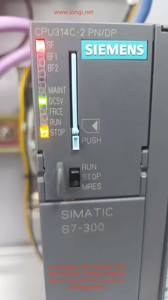
Close-up photo of a SIEMENS SIMATIC S7-300 CPU 314C-2 PN/DP module. The red SF (System Fault) and BF (Bus Fault) LEDs are illuminated, indicating a hardware or communication error.

2. Common Communication Faults Analysis

Siemens S7-300 PLCs often need to exchange data with other devices in industrial automation systems, such as HMIs (Human-Machine Interfaces), remote I/O modules, variable frequency drives, sensors, etc. The following are some common types of communication faults and their analysis:

  1. PROFINET Communication Errors
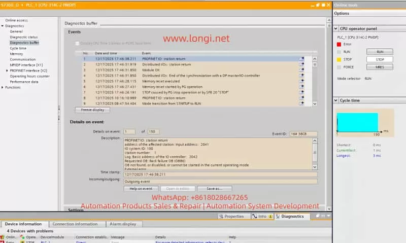
    When using PROFINET for device interconnection, communication between the PLC and network devices may be interrupted or erroneous. A common error is “PROFINET: station return,” which typically indicates that the device did not respond as expected, possibly due to incorrect IP address settings, network cable issues, or improper device configuration.
  2. BUS2F Bus Fault
    When the SF (System Fault) indicator on the PLC lights up red, it typically indicates a communication issue on the PROFIBUS or PROFINET bus. Common causes include module mismatch, hardware failure, or address conflicts.
  3. I/O Module Unresponsiveness
    In complex systems, communication errors between the PLC and I/O modules can prevent the I/O modules from responding correctly. Diagnostic information often shows “Distributed I/O: station return,” indicating that a module failed to synchronize correctly.

3. Diagnostic Steps and Solutions

When encountering communication faults, follow these steps for diagnosis:

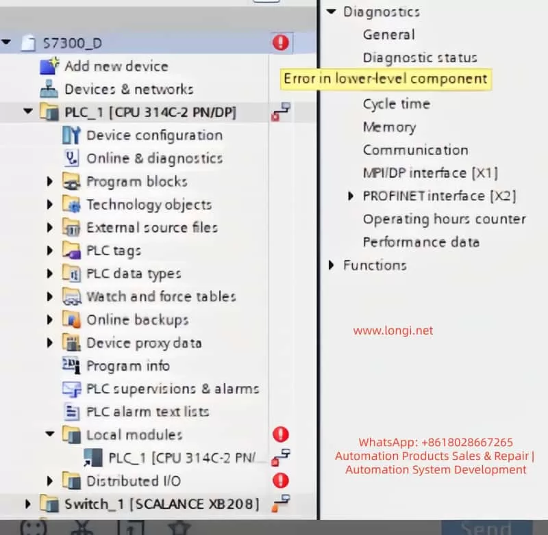
TIA Portal project tree view for a SIMATIC S7-300 PLC project, highlighting the 'Error in lower-level component' diagnostic message and a fault on the SCALANCE XB208 switch.

1. Check PLC Diagnostic Information

In TIA Portal, navigate to the Online and Diagnostics tab to view detailed diagnostic information for the PLC. This can help quickly identify fault codes and the affected devices. Key diagnostic steps include:

  • Open Diagnostic Status and observe the status of Fault LED and Error LED. If the BUS2F or SF indicator is red, it indicates a communication issue.
  • Access the Diagnostic Buffer to view detailed event logs. These logs will help pinpoint the root cause, such as network issues, module failures, or configuration errors.

2. Clear the Error Buffer

When communication errors occur, the first step is to clear the error buffer. This prevents the accumulation of obsolete error logs and ensures accurate diagnostics. Follow these steps:

  • In TIA Portal, select PLC_1 and navigate to the Diagnostics Buffer section.
  • In the diagnostic window, click the Clear button to remove previous error logs. This will clear the error state, making it easier to diagnose the current issue.

3. Restart PLC Communication

If clearing the error buffer doesn’t resolve the issue, try restarting the PLC communication. This can be done in two ways:

  • Restart PLC Operation: In TIA Portal, right-click the PLC and select “Restart” or “Stop/Start” options.
  • Manual Restart: If restarting from TIA Portal doesn’t work, press the RESET button on the PLC, or power cycle the PLC to restart it.

4. Check Device Connections and Network Configuration

The root cause of communication problems is often related to device connections or network configuration errors. Perform the following checks:

  • Check Device Connections: Ensure all devices (e.g., SCALANCE XB208, remote I/O modules, HMI) are correctly connected to the PLC and that network cables are not damaged.
  • Check IP Address Settings: Ensure that the PLC and all connected devices have correctly configured IP addresses and subnet masks. Address conflicts or incorrect settings are common causes of communication failures.
  • Network Topology: Verify that the network topology is correct, with all devices on the appropriate network segments, and ensure there are no loops or address conflicts.

5. Update Firmware

Firmware mismatches are another common cause of communication faults. After checking the hardware version of the devices, ensure that the firmware on both the SCALANCE XB208 and the PLC is compatible. If the firmware is outdated, update it by following these steps:

  • Access Device Management Interface: Log into the device’s web interface to view its firmware version.
  • Download and Install Updates: Visit Siemens’ website to download the latest firmware and perform the update. After updating, restart the device to apply the new firmware.
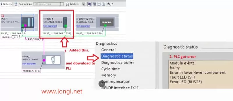
TIA Portal network view showing a SIMATIC S7-300 PLC, a SCALANCE XB208 switch, and fieldbus components, with an indication that the switch was added to the project.

6. Test and Verify the Network

After completing all troubleshooting steps, network communication should be tested to ensure that it has been restored. Use the following methods to verify if the network is functioning properly:

  • Use TIA Portal’s diagnostic tools to perform network tests and check whether the communication between the PLC and other devices has been restored.
  • Ping the PLC and devices using the ping command to test network connectivity.

4. Conclusion

Screenshot of the SIMATIC S7-300 PLC diagnostics buffer in TIA Portal, showing a 'PROFINET IO: station return' error and 'Error in lower-level component' status.

PLC communication problems are common in industrial automation, especially in systems involving multiple devices and complex networks. Through systematic troubleshooting steps, users can effectively diagnose and resolve common PROFINET and PROFIBUS communication issues. Clearing the error buffer, restarting communication, checking device connections, and updating firmware are key steps in resolving communication faults.

This article provides detailed steps for troubleshooting communication issues in Siemens S7-300 PLCs, and aims to help users restore normal operation and improve system reliability and stability.

Posted on

User Guide for Bohui E200 Series Variable Frequency Drive (VFD)

1. Introduction

The Bohui E200 series Variable Frequency Drive (VFD) is a high-performance, reliable vector control inverter widely used in industrial automation, including fans, pumps, textile machinery, machine tools, packaging, and food processing. It supports VF control, open-loop vector control, and closed-loop vector control, and features PLC functionality, PID control, multi-speed operation, and high-speed pulse input.

This guide provides a detailed explanation of the E200 series operation panel, parameter settings, external control wiring, and fault troubleshooting to help users efficiently operate and maintain the device.


2. Operation Panel Overview

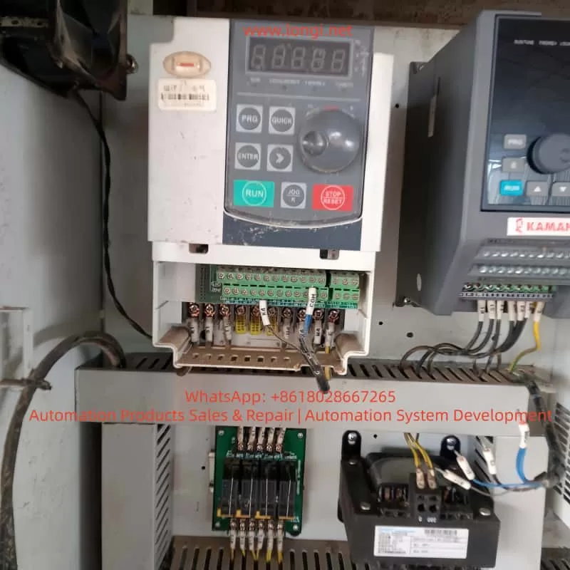
Front panel of E200 VFD

2.1 Panel Buttons and Functions

The E200 series VFD operation panel includes the following buttons:

ButtonFunction
RUNStarts the VFD.
STOP/RESETStops the VFD or resets faults.
MODESwitches between parameter setting and monitoring modes.
UP/DOWNAdjusts parameter values or navigates menus.
ENTERConfirms parameter settings or enters submenus.
JOGUsed for jog operation or command source switching.

2.2 Display Screen Functions

The display screen shows real-time data, including:

  • Running frequency
  • Set frequency
  • Bus voltage
  • Output current
  • Fault codes

Users can customize the display content via F0-00 (Menu Mode Selection).


3. Parameter Settings and Management

3.1 Restoring Factory Default Settings

To reset all parameters to factory defaults:

  1. Press MODE to enter parameter setting mode.
  2. Navigate to F0-47 (Parameter Initialization).
  3. Set F0-47 = 1001 to restore factory settings (excluding motor parameters).
  4. Set F0-47 = 1002 to reset recorded information.
  5. Press ENTER to confirm. The VFD will restart automatically.

3.2 Setting and Removing Password Protection

To prevent unauthorized parameter changes, the E200 supports password protection:

Setting a Password

  1. Enter F0-46 (Password Setting).
  2. Set a non-zero value (e.g., 1234).
  3. Confirm with ENTER. The password will be required to access parameters.

Removing a Password

  1. Enter F0-46.
  2. Set the value to 0.
  3. Confirm with ENTER. Password protection will be disabled.

3.3 Parameter Access Restrictions

The E200 allows different access levels via F0-44 (Parameter Access Level):

LevelAccess Permission
0No restrictions.
1Basic parameter modifications only.
2Most parameter modifications allowed.
3Monitoring only (no modifications).
4Fully locked.

Steps to Set Access Level:

  1. Enter F0-44.
  2. Select the desired level (0~4).
  3. Confirm with ENTER.

4. External Terminal Control and Speed Adjustment

4.1 External Terminal Forward/Reverse Control

The E200 supports forward and reverse control via external terminals.

Wiring Terminals

  • X1: Forward run (default function).
  • X2: Reverse run (requires configuration).
  • COM: Common terminal.

Parameter Settings

  1. Enter F5-00 (X1 Input Function Selection) and set to 1 (Forward Run).
  2. Enter F5-01 (X2 Input Function Selection) and set to 2 (Reverse Run).
  3. Ensure F0-02 (Run Command Channel Selection) is set to 1 (Terminal Control).

Wiring Example:

  • Connect an external switch or PLC output to X1 and X2, with COM as the common terminal.

4.2 External Potentiometer Speed Control

The E200 supports speed adjustment via an external potentiometer (010V or 420mA).

Wiring Terminals

  • AI1: Analog input terminal (default 0~10V).
  • +10V: Reference voltage output.
  • ACM: Analog common terminal.

Parameter Settings

  1. Enter F0-03 (Main Frequency Source Selection) and set to 2 (AI1).
  2. Configure F5-24~F5-27 to set the AI1 input range (e.g., 010V corresponds to 050Hz).
  3. Ensure F0-02 (Run Command Channel Selection) is set to 1 (Terminal Control).

Wiring Example:

  • Connect the potentiometer to AI1 and ACM, and use +10V as the reference voltage.

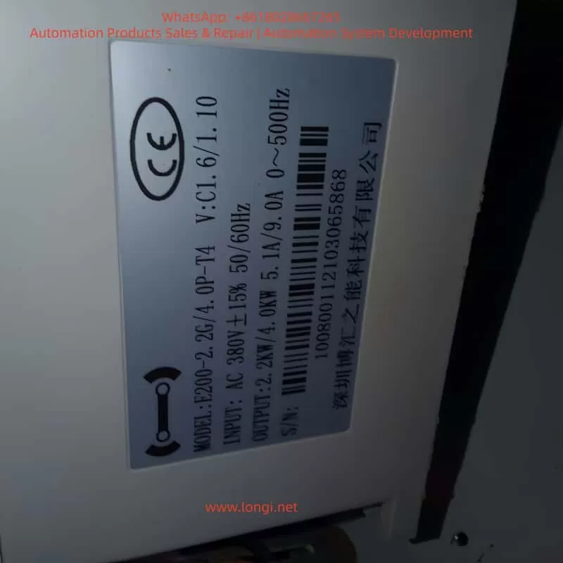
Side (panel/view) of E200 VFD

5. Fault Codes and Troubleshooting

The E200 displays fault codes on the screen or via U0-62 (Current Fault Code). Below are common faults and solutions:

Fault CodeFault NamePossible CauseSolution
OC1Acceleration OvercurrentShort acceleration time, excessive loadIncrease acceleration time (F0-10), check load
OC2Deceleration OvercurrentShort deceleration time, high inertiaIncrease deceleration time (F0-11), add braking resistor
OU1Acceleration OvervoltageHigh supply voltage, insufficient brakingCheck power supply, add braking unit
LUUndervoltage FaultLow supply voltageCheck power supply stability
OL2Motor OverloadMotor overheating, excessive loadCheck motor cooling, reduce load
IPLInput Phase LossMissing input phaseCheck input power wiring
ETFExternal FaultExternal fault signalCheck external control wiring
CoFCommunication FaultCommunication line issueCheck communication interface and wiring

Troubleshooting Steps:

  1. Check U0-62 for the fault code.
  2. Refer to the table above to identify the cause.
  3. Take corrective action.
  4. Press STOP/RESET to clear the fault after resolution.

6. Conclusion

The Bohui E200 series VFD is a powerful and flexible device suitable for various industrial applications. This guide covers operation panel functions, parameter settings, external control wiring, and fault troubleshooting to help users operate the VFD efficiently.

Posted on

**Root Cause Analysis of Malvern Mastersizer Software Exceptions

— From Application Error to Power Management Failure**

1. Background: Mastersizer Software Fails with an Application Exception

The Malvern Mastersizer series (including Mastersizer 2000 and Mastersizer 3000) is widely used in laboratories for laser diffraction particle size analysis. The system combines high-precision optics, detectors, embedded electronics, and complex software layers running on a Windows platform.

In this case, the customer reported that the Mastersizer software fails to start and displays the following message:

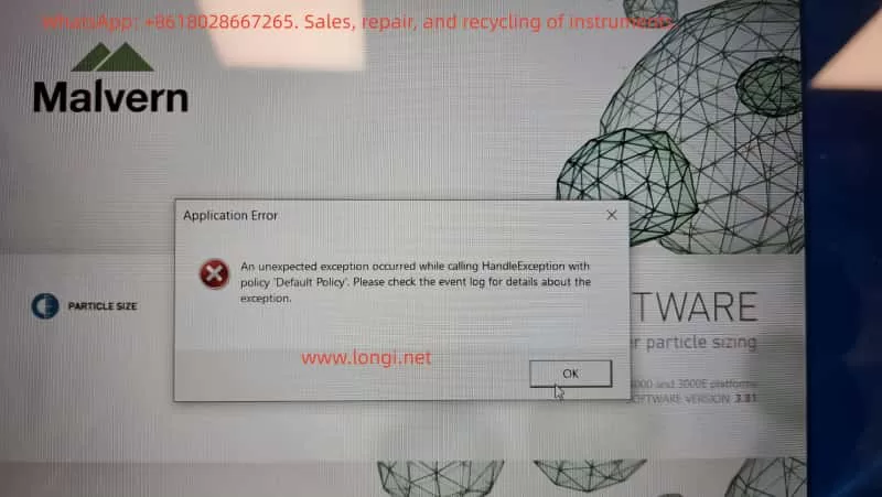
Application Error
An unexpected exception occurred while calling HandleException with policy “Default Policy”. Please check the event log for details about the exception.

Key characteristics of the issue include:

  • The software does not enter the main operating interface
  • The error is generic and non-descriptive
  • The message explicitly refers to Windows Event Logs
  • Reinstalling Windows does not resolve the problem

This type of error is frequently misdiagnosed as a corrupted installation or a simple software incompatibility. However, as shown in this case, the true cause lies deeper.


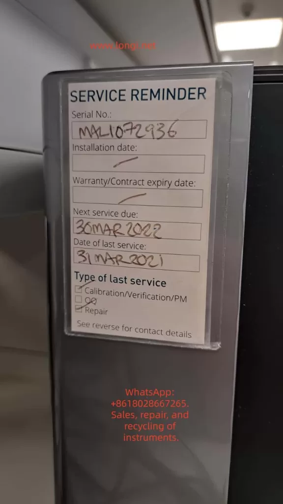
MALI072936

2. A Common Misconception: “Reinstalling Windows Fixes Everything”

From an engineering perspective, the statement:

“The operating system has been reinstalled, but the error remains”

is extremely important.

A clean OS installation normally eliminates:

  • Damaged system files
  • Registry corruption
  • Malware or residual software conflicts
  • User-level configuration issues

When a problem persists after a full OS reinstall, it strongly indicates that:

The fault is not at the Windows installation layer.

This observation immediately shifts the diagnostic focus toward:

  • Hardware state
  • Power management
  • Low-level system services
  • Firmware or driver–hardware interactions

Application Error
An unexpected exception occurred while calling HandleException with policy “Default Policy”. Please check the event log for details about the exception.

3. Event Viewer Analysis: Useful Evidence or a Red Herring?

3.1 Logs Provided by the Customer

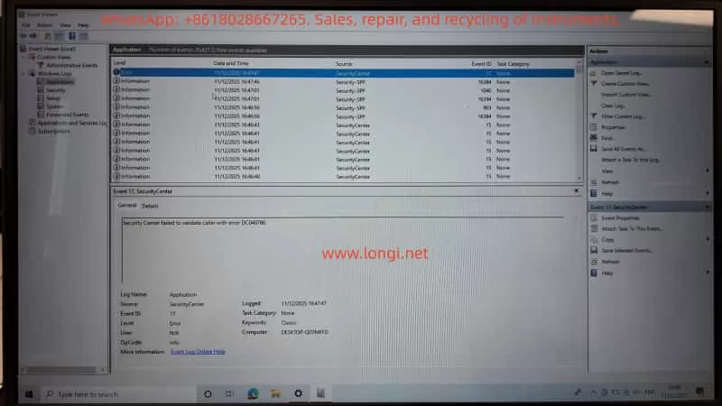
The customer followed instructions and provided multiple screenshots from Windows Event Viewer, specifically:

  • Windows Logs → Application
  • Sources observed:
    • SecurityCenter
    • Security-SPP (Software Protection Platform)

Notable entries included:

  • Event ID 17 – SecurityCenter
    Security Center failed to validate caller with error DC040780
  • Event ID 903 – Security-SPP
    The Software Protection service has stopped
  • Multiple informational events regarding:
    • Defender / McAfee status changes
    • Software Protection service restarts

3.2 Do These Logs Explain the Mastersizer Crash?

From a professional diagnostic standpoint, the answer is:

No — not directly.

Reasons:

  1. Source mismatch
    Mastersizer-related crashes usually appear under:
    • .NET Runtime
    • Application Error
    • Vendor-specific modules
    None of the provided logs reference the Mastersizer application itself.
  2. Severity mismatch
    Most entries are Information level events.
    A software crash severe enough to block startup typically produces a clear Error or Critical event tied to the executable or runtime.
  3. Causal mismatch
    Windows Security Center or Software Protection state changes alone do not cause a specialized instrument control application to fail consistently on a fresh OS.

Conclusion:
These logs indicate system instability, but they are symptoms, not the root cause.


[Security Center failed to validate caller with error DC040780.

4. The Critical Clue: Laptop Battery Stuck at 1% Charge

During troubleshooting, the customer added an apparently unrelated detail:

“The laptop is stuck on 1% charge.”

From an engineering perspective, this is not a minor issue.
It is a high-value diagnostic signal.


5. Power Engineering Perspective: Why 1% Battery Matters

5.1 What “Stuck at 1%” Usually Means

A laptop permanently stuck at 1% charge typically indicates one or more of the following:

  1. Severely degraded battery
    • High internal resistance
    • Battery Management System (BMS) limiting output
    • Battery effectively unusable as a power buffer
  2. Power management or EC firmware issues
    • Embedded Controller (EC) in protection mode
    • Incorrect power state reporting
  3. System forced into extreme low-power operation
    • CPU frequency throttled
    • USB power current limited
    • Peripheral initialization restricted

This is not just a battery indicator problem — it represents a global system power constraint.


5.2 Why This Directly Affects Malvern Mastersizer

The Mastersizer software is not a lightweight application. During startup, it performs:

  • Laser source initialization
  • Detector and photodiode communication
  • USB / PCIe hardware enumeration
  • License and security module validation
  • High-resolution timing and buffer allocation

All of these processes require:

  • Stable voltage rails
  • Predictable timing
  • Reliable peripheral power delivery

When a laptop operates in a forced low-power state:

  • Hardware initialization may time out
  • .NET runtime calls may fail unexpectedly
  • Driver-level calls may return invalid states
  • Exception handlers may be triggered without clear diagnostic messages

This combination often results in exactly the type of error observed:

“An unexpected exception occurred…”


6. Why Reinstalling Windows Cannot Fix This

This is the key engineering insight of the case.

A Windows reinstall cannot repair:

  • A failed battery
  • Power management IC faults
  • Embedded controller firmware states
  • Hardware-enforced power throttling

Even on a completely fresh OS, the system remains constrained by its physical power condition.

As a result:

Any hardware-intensive scientific instrument software may fail unpredictably, even on a clean system.


7. Correct Diagnostic and Recovery Procedure

Step 1: Eliminate Power as a Variable (Highest Priority)

  • Remove or bypass the faulty battery
  • Operate the laptop on a verified, original AC adapter
  • Or replace the battery with a known-good unit
  • Confirm stable charging above 80%

No further software troubleshooting should be performed until this step is completed.


Step 2: Retest Mastersizer Under Stable Power Conditions

  • Launch the Mastersizer software
  • Observe startup behavior
  • If the error disappears, the root cause is confirmed as power management failure

Step 3 (If Needed): Collect Relevant Application Logs

Only if the error persists should further logs be collected:

  • Windows Logs → Application
  • Look specifically for:
    • .NET Runtime
    • Application Error
    • Mastersizer-related modules

These logs provide actionable information at the software layer.


8. Practical Recommendations for Laboratories

For laboratories operating high-precision instruments:

  1. Do not use laptops with degraded batteries as instrument controllers
  2. Treat abnormal power behavior as a system-level fault, not a cosmetic issue
  3. System stability is more critical than OS cleanliness
  4. Instrument software errors are often hardware-condition dependent

9. Final Conclusion

This case demonstrates that:

  • The Mastersizer error is not a simple software bug
  • Event Viewer logs related to Security Center are secondary indicators
  • A laptop stuck at 1% battery is a strong and plausible root cause
  • Power instability can directly trigger non-descriptive application exceptions
  • Reinstalling Windows alone cannot resolve hardware-level constraints

True fault isolation requires understanding the full causal chain:
Power → Hardware → OS Services → Drivers → Application.


10. Closing Remarks

Scientific instrument troubleshooting must go beyond surface-level symptoms.
Only by integrating hardware engineering, power management, operating system behavior, and application architecture can accurate conclusions be reached.

In this case, the Mastersizer software did not “fail randomly” — it failed predictably under abnormal power conditions.

Posted on

Systematic Analysis and Engineering-Level Diagnosis of Communication Failure in Malvern Mastersizer 2000

1. Introduction: Background of the Communication Error

The Malvern Mastersizer 2000 is one of the most widely deployed laser diffraction particle size analyzers worldwide. Its reputation is built on a stable optical system, mature algorithms, and long-term repeatability. However, as the instrument ages, a specific class of failures becomes increasingly common in field applications: loss of communication between the instrument and the host computer.

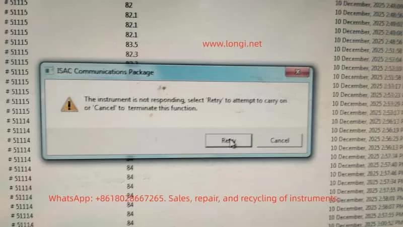
A typical software warning appears as:

ISAC Communications Package
The instrument is not responding

From the user’s perspective, this message is often interpreted as a software crash or a temporary computer issue. From an engineering and maintenance standpoint, however, this error is a clear indicator of a system-level communication failure, involving hardware, power stability, and embedded control reliability rather than measurement parameters or optics.

This article provides a structured, engineering-level analysis of this failure mode in the Mastersizer 2000, focusing on root causes, diagnostic logic, and realistic repair considerations.


Mastersizer 2000,

2. System Architecture Overview of Mastersizer 2000

Understanding this error requires a clear understanding of how the Mastersizer 2000 is architected at a system level.

The instrument can be divided into four major functional subsystems:

  1. Host PC and Malvern control software
  2. Communication layer (ISAC Communications Package)
  3. Internal controller system (embedded control board)
  4. Optical and fluid handling subsystems

The ISAC Communications Package is not merely an application layer component. It is responsible for:

  • Establishing and maintaining the communication session between PC and instrument
  • Periodic polling of instrument status (heartbeat mechanism)
  • Transmission of operational commands (start, stop, align, clean, measure)
  • Receiving and decoding status responses and operational data

When the software reports “Instrument is not responding”, the real meaning is:

The instrument failed to return a valid response within the defined communication timeout window

This indicates a failure somewhere along the communication and control chain, not a measurement error.


3. What This Error Is NOT

Before diagnosing the real cause, it is critical to eliminate several common misconceptions.

3.1 Not a Simple Software Crash

In many cases, background data logging continues even after the warning appears. This confirms that:

  • The Windows operating system is still running
  • The Malvern application itself has not crashed
  • The failure occurs at the communication interface or embedded control level

3.2 Not an Optical or Laser Failure

Failures related to lasers, detectors, or alignment typically result in:

  • Light intensity errors
  • Background measurement failures
  • Optical calibration errors

They do not directly cause a total communication timeout.

3.3 Not a Sample or Method Issue

Sample concentration, dispersion settings, pump speed, or measurement SOPs may affect results, but they do not cause the instrument controller to stop responding at the protocol level.


4. Engineering Interpretation of the Communication Failure

From a system engineering perspective, the error can be summarized as follows:

The host PC cannot complete a communication transaction with the instrument controller within the allowed time

The communication path is a serial chain:

PC software → OS USB stack → PC USB controller → USB cable → instrument USB interface → internal communication module → controller board MCU → response returned

Any instability along this chain will result in the same final symptom: Instrument not responding.


ISAC Communications Package
The instrument is not responding

5. Root Causes in Mastersizer 2000 (Ranked by Probability)

5.1 Unstable USB Communication Path (Highest Probability)

This is the most common cause in aging Mastersizer 2000 units.

Typical symptoms:

  • Instrument is detected, but disconnects during operation
  • Retry sometimes works, sometimes fails
  • Behavior differs between computers
  • Connection drops after several minutes of runtime

Engineering causes:

  • Aging or poorly shielded USB cables
  • Use of USB extension cables or hubs
  • Fatigue or micro-cracks in the instrument USB connector solder joints
  • Degraded internal USB-to-serial communication module

If replacing the USB cable and connecting directly to a motherboard USB port improves stability, the issue is hardware-level communication reliability, not software.


5.2 Controller Board Marginal Operation

After long service life (typically >8–10 years), the controller board often enters a marginal operating state.

Typical symptoms:

  • Cold start works normally
  • Communication fails after warm-up
  • Power cycling temporarily restores operation

Underlying causes:

  • MCU operating near voltage tolerance limits
  • Increased ESR in electrolytic capacitors
  • Power rail ripple exceeding acceptable margins
  • Temperature-related timing instability

This class of failure is often misdiagnosed as intermittent software behavior but is fundamentally a hardware aging issue.


5.3 Internal Power Supply Degradation or Poor Mains Quality

This factor is especially common in regions with unstable mains power.

Contributing conditions:

  • Line voltage fluctuations
  • Lack of voltage regulation
  • Aging internal switching power supplies

Resulting behavior:

  • Momentary drops in 5 V or 3.3 V rails
  • Internal controller or communication module resets
  • PC reports communication timeout

The instrument may appear powered and operational while internally experiencing repeated micro-resets.


5.4 Operating System or Driver Environment (Low Probability)

This factor should only be prioritized when:

  • A new PC has been introduced
  • The operating system was recently reinstalled
  • Non-standard or unofficial software versions are used

In stable legacy systems, OS-level causes are relatively rare.


6. Structured Diagnostic Procedure (Field-Applicable)

A professional diagnostic approach must be systematic and repeatable.

Step 1: Full Cold Reset

  • Shut down software
  • Power off instrument
  • Disconnect power for at least 5 minutes

Step 2: Minimize Communication Path

  • Replace USB cable
  • Eliminate USB hubs or extensions
  • Use rear motherboard USB ports

Step 3: Test with an Alternate Computer

  • Clean OS environment
  • No additional instrument drivers

Step 4: Idle Stability Test

  • Do not perform measurements
  • Maintain connection for at least 10 minutes

If communication still fails under these conditions, the fault can be confidently attributed to instrument-side hardware.


7. Repair and Commercial Considerations

From a third-party service and repair perspective, this fault class has clear implications:

  • It is not a user operation issue
  • Reinstalling software is rarely a true solution
  • In many cases, the instrument is repairable
  • Risk and cost must be evaluated at board level

Viable repair directions:

  • USB connector and communication module repair
  • Controller board power conditioning (capacitors, regulators)
  • Internal power supply refurbishment

Cases where repair is not recommended:

  • Severe multi-board corrosion
  • Controller MCU failure without replacement options

8. Conclusion

The error message “ISAC Communications Package – Instrument not responding” is not vague or generic. In the Mastersizer 2000, it represents a classic aging-related system-level failure involving communication stability and embedded control reliability.

The correct solution is not repeated retries or blind software reinstallation, but:

  • Understanding the communication architecture
  • Differentiating software symptoms from hardware causes
  • Making informed engineering and commercial repair decisions
Posted on

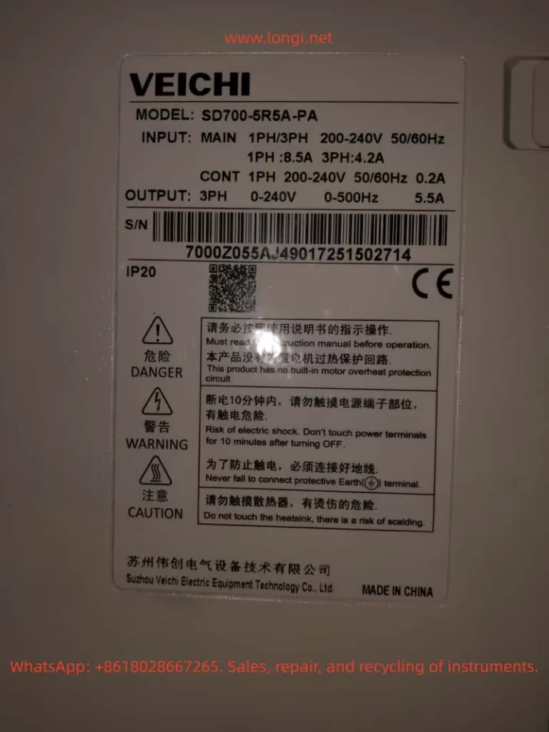
Analysis and Systematic Solutions for ER.022 Fault in Weichuang Servo SD700 Series

Introduction

In the field of modern industrial automation, servo systems are the core components for high-precision motion control, and their stability and reliability directly impact the efficiency and product quality of production lines. The SD700 series servo drives launched by Weichuang Electric have gained market recognition due to their excellent performance and wide applications. However, in actual operation, the ER.022 fault code, as a common system abnormality alert, poses a challenge to technicians. This article will provide a systematic technical guide for technicians from the aspects of definition, causes, diagnosis, solutions, and prevention.

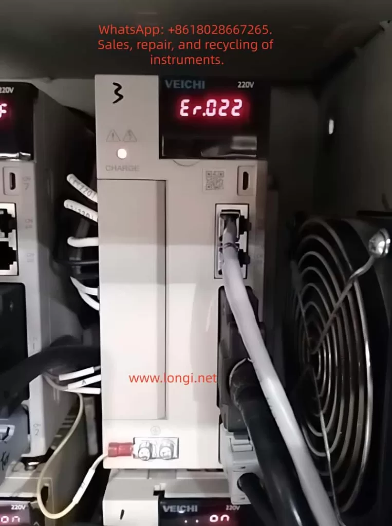
ER.022 fualt

I. Overview of the ER.022 Fault Code

1.1 Definition of the Fault Code

The ER.022 fault code in the Weichuang Servo SD700 series represents a “system and checksum anomaly,” indicating that the servo drive has detected inconsistencies in system parameters, data, or checksums during self-check or operation, which may be caused by software errors, hardware failures, or external interference.

1.2 Fault Phenomena

When the SD700 series servo drive experiences an ER.022 fault, it is usually accompanied by the following phenomena:

  • The fault indicator light on the drive panel illuminates, displaying the ER.022 error code.
  • The servo motor stops running and fails to respond to control commands from the host computer.
  • The drive may automatically enter a protective state.

II. Analysis of the Causes of the ER.022 Fault

2.1 Software Errors

  • Loss or Damage of System Parameters: Parameters may be lost or damaged during storage or transmission due to sudden power outages or electromagnetic interference.
  • Incompatibility of Firmware Versions: The firmware may be incompatible with the host computer software or other devices.
  • Software Defects: The servo drive software may have undiscovered defects or vulnerabilities.

2.2 Hardware Failures

  • Memory Failures: Non-volatile memories such as EEPROMs and Flash memories may age, be damaged, or have write errors.
  • Processor Failures: The CPU or DSP may operate abnormally due to overheating, voltage instability, or manufacturing defects.
  • Communication Interface Failures: Data transmission errors may occur due to poor contact, damage, or protocol mismatches in communication lines.

2.3 External Interference

  • Electromagnetic Interference: Electromagnetic interference may be generated by frequency converters, high-voltage cables, etc., in the surrounding environment.
  • Power Supply Fluctuations: Unstable power supplies may cause abnormal operation of internal circuits in the drive, such as voltage dips or surges.
SD700 weichi drive

III. Diagnostic Process for the ER.022 Fault

3.1 Preliminary Checks

  • Confirm Fault Phenomena: Check the fault indicator light and error code on the drive panel.
  • Check Power Supply: Use a multimeter to measure the input power supply voltage to ensure it is stable without fluctuations.
  • Check Communication Lines: Check the connection status of communication lines to ensure there are no loose or damaged parts.

3.2 In-Depth Diagnosis

  • View Fault Logs: View fault logs through the host computer software or drive panel.
  • Parameter Backup and Restoration: Back up parameters and then perform initialization operations to restore factory settings. Reconfigure parameters and observe whether the fault disappears.
  • Firmware Upgrade: Check and upgrade the firmware version.
  • Hardware Detection: Use professional testing tools to detect key components such as memories, processors, and communication interfaces.

IV. Solutions for the ER.022 Fault

4.1 Software Solutions

  • Parameter Initialization and Reconfiguration:
    • Back up parameters to an external storage device.
    • Perform initialization operations to restore factory settings.
    • Reconfigure parameters according to requirements and observe whether the fault disappears.
  • Firmware Upgrade:
    • Download the latest firmware file from the official website.
    • Burn the firmware using the host computer software or a dedicated programmer.
    • Restart the drive and observe whether the fault disappears.

4.2 Hardware Solutions

  • Replace Memory: If memory failure is suspected, try replacing the EEPROM or Flash memory and reconfigure parameters.
  • Replace Processor: If processor failure is confirmed, replace the entire drive or processor module and reconfigure parameters and upgrade the firmware.
  • Repair Communication Interface: Check the connection status of communication lines and replace the communication interface module or the entire drive.

4.3 Solutions for External Interference

  • Electromagnetic Shielding: Perform electromagnetic shielding treatment on the drive and surrounding equipment and use shielded cables for connections.
  • Stable Power Supply: Provide a stable and reliable power supply and use a UPS or voltage regulator to ensure power quality.

V. Preventive Measures and Routine Maintenance

5.1 Preventive Measures

  • Regular Parameter Backup: Regularly back up parameters for quick restoration.
  • Avoid Sudden Power Outages: Avoid sudden power outages during operation as much as possible.
  • Use Genuine Software: Ensure that genuine software and firmware from the official source are used.

5.2 Routine Maintenance

  • Cleaning and Dust Prevention: Regularly clean the drive and surrounding equipment to keep them clean and well-ventilated.
  • Check Connection Lines: Regularly check whether connection lines are properly connected without looseness or damage.
  • Monitor Operating Status: Monitor the operating status and parameter changes of the drive through the host computer software or drive panel to promptly detect and handle potential problems.

VI. Conclusion

The ER.022 fault, as a common system abnormality alert in the Weichuang Servo SD700 series, has causes involving software errors, hardware failures, and external interference. Through a systematic diagnostic process and solutions, technicians can effectively locate and solve the problem to ensure the stable operation of the servo system. Meanwhile, taking preventive measures and strengthening routine maintenance can reduce the probability of fault occurrence and improve the efficiency and product quality of production lines.

Posted on

Comprehensive Analysis of SSF Fault in Schneider Electric Altivar ATV71 Inverter

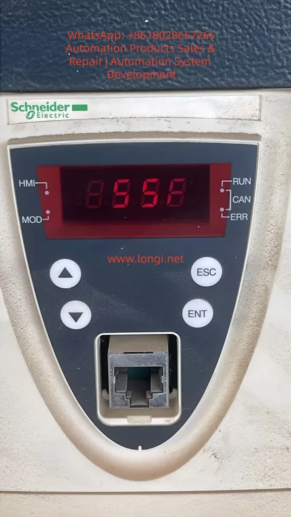
Schneider Electric Altivar ATV71, a classic high-performance inverter, is widely used in the field of industrial automation. However, in practical use, the SSF (Torque or Current Limitation Fault) has become one of the more common faults, especially being easily misread as “S5F” or “55F” on the seven-segment LED display. This article will provide an in-depth analysis of the generation mechanism, triggering conditions, common causes, diagnostic methods, troubleshooting steps, and preventive measures for the SSF fault.

I. Overview of SSF Fault

The SSF fault indicates that the inverter has been in a torque or current limiting state for an extended period, and after exceeding the set timeout time, it triggers a protective shutdown. This is a “soft” protective fault. Unlike instantaneous hard protections such as SCF (Motor Short Circuit) or OCF (Overcurrent), it is based on time judgment and aims to protect the motor and mechanical system from damage caused by long-term high-load operation.

II. Characteristics and Misreading of SSF Fault Code

The integrated HMI of the ATV71 uses a seven-segment LED display. The SSF fault code may be misread as “S5F” or “55F” due to display aging, dust coverage, or improper viewing angles. The official manual clearly states that SSF is a torque or current limitation fault, and users can view the actual fault code through the graphic terminal or SoMove software to confirm.

III. Triggering Mechanism of SSF Fault

The control algorithm of the ATV71 continuously monitors the output current and estimates the torque in real time. When the actual current reaches or exceeds the current limit value (CLI), or the estimated torque reaches or exceeds the torque limit value, and the duration exceeds the set timeout time (Sto), the drive will trigger the SSF fault and shut down.

IV. Common Causes of SSF Fault

Mechanical Load Aspect

  • Sudden increase in load
  • Increased mechanical friction
  • Changes in the inertia of the transmission system or process variations

Improper Parameter Configuration

  • Excessively short Sto setting
  • Current/torque limit values set too low
  • Incorrect motor nameplate parameters or excessively short acceleration/deceleration times

Control Mode and Tuning Issues

  • Failure of sensorless vector control tuning
  • Using V/F control for high-inertia loads or improper PID control parameters

Electrical and Environmental Factors

  • Power supply voltage fluctuations
  • High ambient temperature
  • Excessively long output cables or parallel operation of multiple motors

Potential Hardware Problems

  • Aging of IGBT modules
  • Drift of current sensors or control board failures

V. Diagnostic Process for SSF Fault

On-site Preliminary Confirmation

  • Record the operating state at the time of the fault occurrence, check the fault history, and monitor the current, torque, output frequency, and drive thermal state at the moment of the fault.

Parameter Check and Temporary Adjustment

  • Adjust the Sto parameter, check the current and torque limit values, confirm the motor parameters, and perform automatic tuning.

Mechanical System Inspection

  • Manually rotate the shaft to check for mechanical jamming, inspect the transmission components, and measure the actual load current.

Electrical Testing

  • Check the stability of the input voltage, measure the balance of the motor’s three-phase currents, and consider adding an output reactor.

Advanced Diagnosis

  • Use SoMove software to view real-time curves, execute test programs, and contact Schneider service.
SSF FAULT

VI. Troubleshooting and Solutions for SSF Fault

Parameter Optimization

  • Increase the Sto value, raise the CLI, set the torque limit value reasonably, and extend the acceleration/deceleration times.

Mechanical System Improvement

  • Lubricate the bearings, adjust the belt tension, clear blockages, and optimize the process load.

Control Strategy Adjustment

  • Perform a complete automatic tuning, optimize the PID parameters, and switch to closed-loop control with an encoder.

Hardware Supplementation

  • Add an output reactor, enhance cooling or operate at a reduced rating, and add a braking unit/resistor.

Reset Methods

  • Press the panel STOP/RESET key, reset through an assigned digital input, or enable the automatic restart function.

VII. Typical Case Studies

Conveyor Belt Application

  • Problem: During startup, a sudden increase in coal volume caused the current to瞬间 (momentarily) reach 160% and remain for 2 seconds, with the original Sto set at 100 ms.
  • Solution: Change the Sto to “Cont” and optimize the material loading process.

Constant-pressure Water Supply in a Pump Station

  • Problem: One pump’s impeller was entangled with debris, causing uneven load.
  • Solution: Clean the impeller, redistribute the load, and increase the Sto value.

Crane Hoisting

  • Problem: During the deceleration phase, regenerative energy triggered the torque limit.
  • Solution: Set the reverse torque limit reasonably and add a braking resistor.

Fan Application

  • Problem: In a high-temperature workshop during summer, the drive automatically derated.
  • Solution: Strengthen the ventilation of the cabinet and install an air conditioner.

VIII. Preventive Measures for SSF Fault

Parameter Rationalization

  • Adjust the Sto value before the commissioning of a new project and reserve current/torque margins.

Regular Maintenance

  • Regularly inspect the mechanical transmission system, clean the drive’s radiator, perform motor insulation tests, and execute automatic tuning.

Monitoring and Early Warning

  • Continuously monitor the current/torque curves and provide early warnings when approaching the limit state.

Training and Documentation

  • Establish standard operating procedures and save parameter modification records.

IX. Conclusion

Although the SSF fault is common, it can be quickly resolved through systematic analysis and targeted measures. Proper handling of the SSF not only eliminates the fault but also improves system stability and efficiency. It is recommended to use the official programming manual as the standard in actual maintenance, conduct in-depth diagnosis with the help of SoMove software, and promptly contact Schneider Electric technical support for professional solutions.