
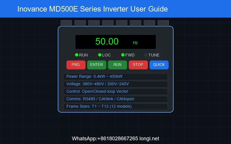
Inovance MD500E Series Inverter User Guide: Comprehensive Manual from Installation to Troubleshooting
The Inovance MD500E series is a general-purpose high-performance vector control inverter designed to control and regulate the speed and torque of three-phase AC synchronous motors. It is widely used in textile, papermaking, wire drawing, machine tools, packaging, food processing, fans, pumps, and various automated production equipment. This article is based on the official user manual (689 pages, version B05) and provides a systematic operational guide for industrial control technicians, covering six major dimensions: product overview, installation and wiring, operation panel usage, terminal control configuration, parameter settings and password management, and fault code diagnosis.
1. Product Overview and Technical Specifications
The MD500E series covers a power range from 0.4kW to 450kW, supporting both three-phase 380V~480V and three-phase 200V~240V voltage levels, with frame sizes from T1 to T12 (12 specifications in total). The core control methods include open-loop vector control (SVC) and closed-loop vector control (FVC). In SVC mode, the starting torque reaches 0.25Hz/150%, speed regulation range is 1:200, and speed stability accuracy is ±0.5%. In FVC mode, the starting torque reaches 0Hz/180%, speed regulation range is 1:1000, and speed stability accuracy is ±0.02%.
For frequency sources, the MD500E supports 10 types of frequency command inputs: digital setting (power-off memory/non-memory), analog input (AI1/AI2/AI3), pulse input (DI5, up to 100kHz), multi-speed, simple PLC, PID, and communication setting, with flexible switching between methods. Run commands support operation panel, control terminal, and serial communication port inputs. Communication supports three fieldbus protocols: RS485 (Modbus-RTU), CANlink, and CANopen.
Protection features include input/output phase loss protection, instantaneous overcurrent protection (trips at 250% of rated current peak), overvoltage protection (DC bus voltage above 820V), undervoltage protection (DC bus voltage below 350V), overheating protection, overload protection (trips after 60s at 150% rated current at 40°C), short circuit protection (output phase-to-phase and ground fault), and braking protection.
2. Installation and Wiring Essentials
Installation Environment: The MD500E inverter must be installed indoors with ambient temperature from -10°C to +50°C (derating required above 40°C, 1.5% per °C increase), humidity ≤95%RH non-condensing, and altitude below 1000m without derating (1% derating per 100m above 1000m). The mounting direction must be vertical; horizontal, side-lying, or inverted installation is prohibited. T1~T9 frames support wall-mounted and flush-mounted installation, while T10~T12 frames only support single-unit cabinet installation.
Thermal Design: When designing the cabinet, the effective area of air intake and exhaust openings must be considered. For example, a T3 (7.5kW) unit requires a minimum intake area of 50cm² and a minimum passive exhaust area of 80cm². For multiple inverters in one cabinet, the required cooling air volume must be accumulated, and the cabinet fan’s maximum air volume should be 1.3~1.5 times the total cooling air volume of all inverters.
Main Circuit Wiring: T1~T4 frame main circuit terminals include R/S/T (three-phase power input), U/V/W (motor output), and +/BR (braking resistor connection). T5 and above frames also feature DC bus positive and negative terminals (+) and (-) for common DC bus or external braking unit connection. Terminal screws must be tightened according to the specified torque values, ranging from 4.8N·m to 85N·m depending on the frame size.
Control Circuit Wiring: Standard control terminals include:
- Power terminals: +10V (external potentiometer power, max 10mA), +24V (digital I/O power, max 200mA), OP (external power input, factory-default shorted to +24V)
- Analog inputs: AI1 (0~10V voltage input), AI2 (0~10V voltage or 0~20mA current, selected by J9 jumper)
- Digital inputs: DI1~DI4 (optocoupler isolated, 9V~30V operating voltage), DI5 (high-speed pulse input, up to 100kHz)
- Output terminals: AO1 (analog output, 0~10V or 0~20mA, selected by J7 jumper), DO1 (digital output, 0~24V/50mA), FM (high-speed pulse output, up to 100kHz), T/A-T/B-T/C (relay output, 250V AC/3A or 30V DC/1A)
- Communication: 485+/485- (RS485 interface)
Digital input terminals support both sink and source wiring modes. In sink wiring with internal 24V power, OP must be shorted to +24V; with external power, the shorting tab between OP and +24V must be removed. When paralleling DI terminals across multiple inverters, a diode (IF>40mA, VR>40V) must be connected in series to prevent malfunction.
3. LED Operation Panel Detailed Guide
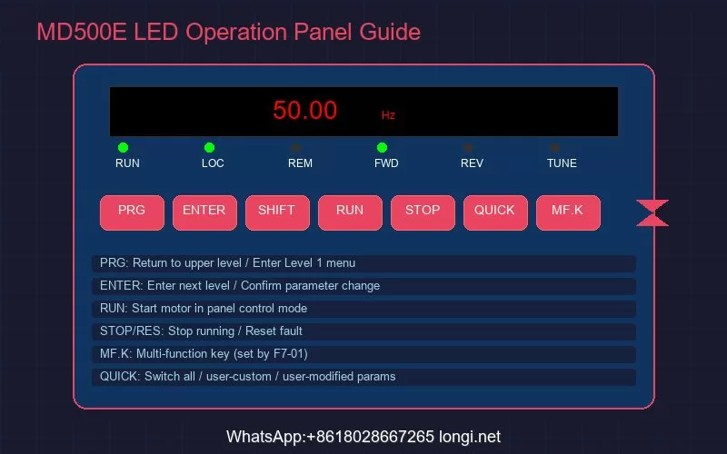
The MD500E is equipped with an LED operation panel that displays running status, enables parameter setting, and shows fault information. The panel uses a three-level menu structure: level 1 is the parameter group (e.g., F0, F1, F2), level 2 is the specific parameter (e.g., F0-02), and level 3 is the parameter setting value.
Key Functions:
- PRG (Program key): Return to previous screen or enter level 1 menu
- ENTER (Confirm key): Enter next screen, confirm parameter changes
- Increment/Decrement keys: Increase or decrease parameter numbers and setting values
- Shift key: Select the digit to modify when setting parameters
- RUN key: Start the motor in panel control mode
- STOP/RES key: Stop during running, reset during fault state
- MF.K (Multi-function key): Function set by parameter F7-01
- QUICK key: Switch between parameter display modes (all parameters / user-customized / user-modified)
Panel Indicators:
- RUN lamp: Off = stopped, On = running
- LOCAL/REMOT lamp: Off = panel control, On = terminal control, Blinking = communication control
- FWD/REV lamp: Off = forward, On = reverse
- TUNE/TC lamp: Off = normal, On = torque control, Slow blink = parameter identification (1/sec), Fast blink = fault (4/sec)
MF.K Multi-function Key: Parameter F7-01 offers 5 options: 0=disabled, 1=switch between panel and remote command channels, 2=forward/reverse switching, 3=forward jog, 4=reverse jog. The forward/reverse switching and jog functions are only effective when the command source is the operation panel. Parameter F7-02 controls the STOP/RESET key scope: 0=effective only in keyboard mode, 1=effective in all operation modes.
Quick Parameter Lookup: Press the QUICK key to switch between three parameter display modes — full parameter mode shows all function codes; user-customized mode shows up to 30 user-selected parameters (defined via FE group); user-modified mode automatically lists parameters that differ from factory defaults, enabling quick identification of changed settings.
4. Terminal Control and Run Configuration
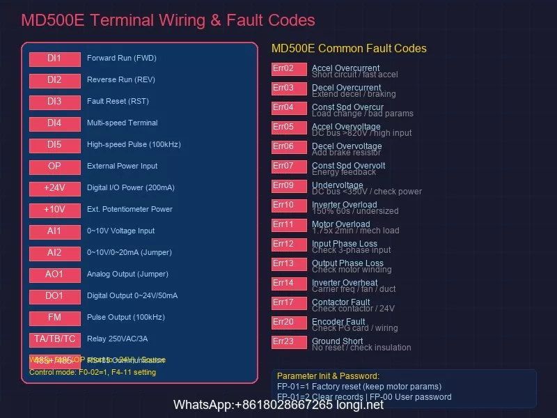
Parameter F0-02 selects the run command input channel: 0=operation panel, 1=terminal, 2=communication. When terminal control is selected (F0-02=1), parameter F4-11 sets the terminal command control mode, supporting four patterns:
Two-wire Mode 1 (F4-11=0): The most commonly used mode. For example, DI1 set to forward run (F4-00=1), DI2 set to reverse run (F4-01=2). SW1 closed = forward, SW2 closed = reverse; both open or both closed = motor stops.
Two-wire Mode 2 (F4-11=1): DI1 set to run command, DI2 set to forward/reverse direction. SW1 closed enables running; SW2 open = forward, SW2 closed = reverse.
Three-wire Mode 1 (F4-11=2): DI3 set to three-wire run control (normally closed button), DI1 set to forward run, DI2 set to reverse run. With SW3 closed, pressing SW1 starts forward, pressing SW2 starts reverse; opening SW3 stops the inverter.
Three-wire Mode 2 (F4-11=3): DI3 set to three-wire run control, DI1 set to run command, DI2 set to forward/reverse direction. With SW3 closed and SW1 pressed, the inverter runs; SW2 open = forward, SW2 closed = reverse.
Multi-speed Control: The MD500E supports up to 16-speed operation, selected by the combined signals of 4 DI terminals. Set F0-03=6 to select multi-segment command as the main frequency source, with each speed value set via FC-00~FC-15 parameters. The relationship between DI terminal count and speed count: 1 DI = 2 speeds, 2 DIs = 4 speeds, 3 DIs = 8 speeds, 4 DIs = 16 speeds.
Frequency Command Setting: In addition to multi-speed, the MD500E supports setting the main frequency via analog input (AI1/AI2/AI3), pulse input (DI5), panel digital setting, communication, simple PLC, and PID. Parameter F0-03 selects the main frequency source X, and F0-07 sets the frequency source superposition method, enabling flexible configurations such as addition/subtraction of main and auxiliary frequencies or taking the maximum value.
5. Parameter Initialization and Password Management
Factory Reset: Parameter FP-01 executes parameter initialization with the following options:
- FP-01=0: No operation
- FP-01=1: Restore factory parameters (Mode 1) — most function parameters are restored to factory defaults, but motor parameters, frequency decimal point (F0-22), fault records, cumulative running time (F7-09), cumulative power-on time (F7-13), cumulative power consumption (F7-14), and heatsink temperature (F7-07) are not restored
- FP-01=2: Clear record information — clears fault records and cumulative running/power-on time/power consumption
- FP-01=4: Backup current user parameters
- FP-01=501: Restore user backup parameters
User Password: The FP parameter group includes user password functionality (FP-00), which can be set to protect parameters from unauthorized modification. Once a password is set, entering the correct password is required to edit parameters again. If the password is forgotten, contact the manufacturer or authorized service center for unlocking.
Parameter Group Display: Parameter FP-02 controls whether U, A, B, and C parameter groups are displayed on the operation panel. Parameter FP-03 controls the display of user-customized and user-modified parameter groups, streamlining menu navigation as needed.
Motor Parameter Identification: Correct motor parameter settings are essential for optimal vector control performance. After setting F1-00 (motor type, default 2 = permanent magnet synchronous motor), F1-01 (rated power), F1-02 (rated voltage), F1-03 (rated current), F1-04 (rated frequency), and F1-05 (rated speed) according to the motor nameplate, set F1-37=2 and press and hold the RUN key for more than 3 seconds to start parameter identification. During identification, the TUNE/TC indicator blinks slowly, and after approximately 1 minute, the panel displays 50.00 indicating completion.
6. Fault Code Reference and Troubleshooting
The MD500E inverter features comprehensive fault detection and protection mechanisms. Fault codes are prefixed with “Err” followed by a two-digit number. Below are common fault codes and troubleshooting methods:
Overcurrent Faults:
- Err02 (Acceleration Overcurrent): Current exceeds 2.5 times rated current peak during acceleration. Check for output circuit short circuits, verify motor parameter identification was performed, check if acceleration time (F0-17) is too short, and verify overcurrent stall suppression parameters (F3-18/F3-19/F3-20)
- Err03 (Deceleration Overcurrent): Current exceeds limit during deceleration. Extend deceleration time (F0-18) and check braking resistor configuration
- Err04 (Constant Speed Overcurrent): Current exceeds limit during constant speed operation. Check for sudden load changes and verify motor parameter correctness
Overvoltage Faults:
- Err05/Err06/Err07 (Acceleration/Deceleration/Constant Speed Overvoltage): DC bus voltage exceeds 820V. Deceleration overvoltage is common with high-inertia loads; configure braking resistors or increase deceleration time. Overvoltage stall function (F3-22/F3-23/F3-24/F3-25) can automatically limit voltage rise
Other Common Faults:
- Err09 (Undervoltage): DC bus voltage below 350V — check input power supply
- Err10 (Inverter Overload): Trips after 60s at 150% rated current at 40°C — check if load is too large or inverter is undersized
- Err11 (Motor Overload): Based on inverse time curve, trips at 1.75× rated current for 2 minutes or 1.15× rated current for 80 minutes. Check motor load, F1 group motor parameters, and F9 group overload protection parameters
- Err12/Err13 (Input/Output Phase Loss): Check three-phase input power balance and output-to-motor wiring reliability
- Err14 (Inverter Overheating): Check if carrier frequency (F0-15) is too high, fan is damaged, or air duct is blocked
- Err17 (Contactor Fault): Check soft-start contactor cable and 24V power supply
- Err20 (Encoder Fault): Check encoder wiring and PG card configuration; verify encoder line count, type, and direction settings
- Err23 (Output Ground Short Circuit): This fault cannot be reset — use a megger to check motor and output cable insulation
Fault Reset and Diagnosis: Most faults can be reset by pressing the STOP/RES key or power cycling (except Err23). For overcurrent or overload faults during startup in open-loop vector control mode (F0-01=0), focus on verifying motor parameter identification completion and checking speed loop parameters (F2-00/F2-01 for low frequency, F2-03/F2-04 for high frequency). In closed-loop vector control mode (F0-01=1), also confirm encoder wiring, line count, and direction settings are correct.
7. Routine Maintenance and Care
To ensure long-term stable operation of the MD500E inverter, the following periodic inspections are recommended:
- Daily inspection: Observe for abnormal running conditions (noise, odor, temperature anomalies), verify cooling fan operation, and confirm air intake/exhaust openings are unobstructed
- Periodic inspection: Check main circuit terminal screws for looseness (re-tighten to specified torque), measure main circuit insulation resistance (disconnect control board and use 500V megger), and inspect electrolytic capacitors for swelling or leakage
- Consumable replacement: Cooling fan life is approximately 20,000~30,000 hours (depending on environment), and filter capacitor life is approximately 5~8 years; replace when end of life is reached
- Storage requirements: For long-term storage, maintain ambient temperature at -20°C~+60°C and power on for a test run every 6 months to maintain electrolytic capacitor performance
Conclusion
The Inovance MD500E series inverter, with its rich control functions, flexible configuration options, and comprehensive protection mechanisms, can meet the driving requirements of various industrial automation scenarios. Correctly understanding the operation panel usage, properly configuring terminal control schemes, following standardized parameter setting procedures, and mastering fault diagnosis techniques are key to fully leveraging the product’s performance. In practical applications, technicians are advised to conduct meticulous commissioning according to the official manual based on specific working conditions, and establish a regular maintenance system to ensure long-term reliable equipment operation.
For more technical support, product selection, or repair services regarding Inovance inverters, please contact professional industrial control service providers.