
Mitsubishi MELSERVO-JE servo systems are widely used in CNC machinery, packaging equipment, printing machines, automated assembly lines, conveying systems, feeding mechanisms, and auxiliary robot axes. These servo systems are known for accurate positioning, stable speed control, relatively simple parameter configuration, and good compatibility with industrial automation equipment.
During operation, however, a Mitsubishi MR-JE servo amplifier may generate overload-related alarms because of mechanical seizure, an unreleased electromagnetic brake, incorrect motor wiring, unsuitable gain settings, excessive load inertia, or insufficient motor capacity.
One of the most important alarms in this category is:
AL.51.2 — Thermal Overload Error During Stop 3
This alarm does not simply mean that the motor surface temperature is high. It means that, while the motor is stopped, holding position, locked at zero speed, or mechanically stalled, the servo amplifier has continued to supply an abnormally high current. Based on its internal electronic thermal model, the amplifier determines that the motor or power stage has reached an unsafe overload condition.
Compared with overload alarms that occur during acceleration or continuous running, AL.51.2 is more closely associated with mechanical blockage, failure of the motor brake to release, excessive holding torque, zero-speed oscillation, incorrect U-V-W motor wiring, encoder feedback problems, and undersized motor selection.
Resetting the alarm without removing the root cause is not a valid repair. The alarm will usually return, and repeated forced operation may damage the motor winding, servo amplifier power module, coupling, ballscrew, gearbox, or brake mechanism.
This article explains the operating principle behind AL.51.2, the most common causes, the correct field diagnostic sequence, electrical measurement methods, MR Configurator2 analysis, and practical repair procedures.
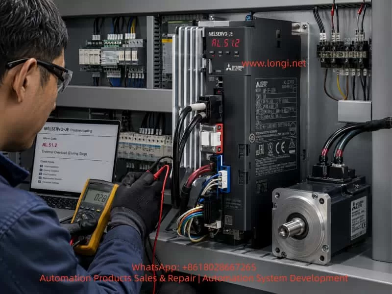
1. What AL.51.2 Actually Means
A stopped servo motor is not necessarily an electrically inactive motor.
When the Servo ON signal remains active, the servo amplifier continues to control the motor even when the commanded speed is zero. The amplifier constantly compares the commanded position with the encoder feedback position. If an external force attempts to move the motor shaft, or if the actual position differs from the target position, the amplifier generates corrective torque.
For example, consider a vertical lifting axis. When the axis reaches its commanded position, the motor speed becomes zero, but gravity continues to pull the load downward. If the brake has not yet engaged, the servo motor must produce holding torque to prevent the load from falling.
The amplifier continuously evaluates factors such as:
- Motor output current
- Duration of high current
- Motor rated capacity
- Amplifier rated capacity
- Zero-speed operating condition
- Load ratio during acceleration, deceleration, and holding
- Thermal accumulation in the power stage
- Estimated motor winding temperature
When high current continues for too long while the motor is stopped, the electronic thermal protection function activates and generates AL.51.2.
The essential meaning of the alarm is therefore:
The motor is stopped, but the servo system is still producing abnormally high torque and current.
2. Why a Servo Motor Can Overload While Stopped
A servo system usually contains three nested control loops:
- Current loop
- Speed loop
- Position loop
When the motor reaches its target position, the position loop remains active. If the encoder detects even a small position error, the controller creates a speed correction command. The speed loop then produces a torque command, and the current loop regulates the three-phase current supplied to the motor.
Under normal conditions, only a moderate current is needed to hold position. However, if the motor cannot move or if the load continuously applies a large external force, the amplifier increases torque.
High current at zero or near-zero speed is especially dangerous because motor cooling is often poor in this condition. Motor copper loss follows the relationship:
[
P_{\text{Cu}}=I^2R
]
Where:
- (P_{\text{Cu}}) is winding copper loss
- (I) is motor current
- (R) is winding resistance
If motor current doubles, copper loss theoretically increases by a factor of four. For this reason, a stalled servo motor may overheat much faster than expected, even if the motor housing does not immediately feel hot.
Typical conditions that produce high current while stopped include:
- The machine has reached a mechanical end stop
- A ballscrew, guide rail, or gearbox is jammed
- The electromagnetic brake has not released
- A vertical load is too heavy
- The encoder feedback is unstable or incorrect
- U, V, and W motor phases are incorrectly connected
- The motor is oscillating around the holding position
- Servo gains are too high
- Load inertia is excessive
- The motor is undersized
- A coupling or bearing is seized
- The controller continues issuing position commands after the mechanism has stopped
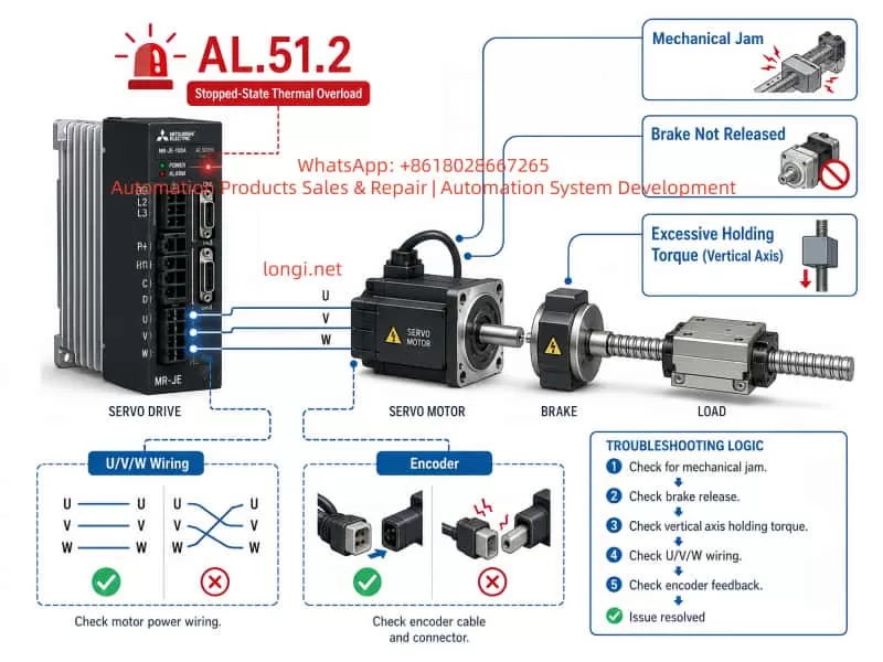
3. Difference Between AL.51.2 and General Running Overload
The most important diagnostic feature of AL.51.2 is that it occurs under a stopped or zero-speed condition.
If an overload alarm occurs during high-speed operation, acceleration, or repeated production cycles, the main areas to inspect are normally:
- Excessive moving load
- Acceleration time too short
- Deceleration time too short
- Excessive load inertia
- Increased mechanical friction
- Insufficient motor capacity
If the alarm occurs after positioning is complete, immediately after Servo ON, or while the shaft is holding still, priority should be given to:
- Mechanical blockage
- Brake release failure
- Excessive holding torque
- Vertical-axis imbalance
- Zero-speed oscillation
- Incorrect motor wiring
- Encoder feedback problems
- Incorrect servo parameter settings
The time at which the alarm appears is often more useful than the alarm code alone.
4. Mechanical Seizure Is the Most Common Cause
Mechanical blockage is one of the most frequent causes of AL.51.2.
Typical mechanical problems include:
- Seized ballscrew
- Dry or damaged linear guide
- Broken linear bearing
- Worn gearbox
- Damaged gearbox gear
- Misaligned coupling
- Broken coupling insert
- Overtightened belt
- Seized motor bearing
- Foreign material inside the mechanism
- Workpiece interference
- Clamp or cylinder not retracted
- Machine axis hitting a hard stop
- Vertical-axis counterweight failure
- Incorrect mechanical assembly alignment
When the machine cannot move but the controller continues to command movement, the position error increases. The servo amplifier responds by increasing torque.
Typical field symptoms include:
- The motor produces a low-frequency humming sound
- The shaft does not rotate
- The motor heats quickly
- The coupling or ballscrew vibrates
- The torque monitor approaches 100%
- Position deviation or droop pulses continue increasing
- The alarm appears a few seconds after the axis stops
- The same movement always produces the same alarm
The most effective diagnostic method is to disconnect the motor from the load.
After removing the coupling, belt, or gearbox connection, inspect the motor and the mechanical mechanism separately.
The machine mechanism should move smoothly without:
- Hard points
- Sudden resistance
- Metallic noise
- Intermittent locking
- Excessive friction
- Abnormal backlash
If the servo motor operates normally after being disconnected from the load, the problem is almost certainly on the mechanical side.
5. Failure of the Electromagnetic Brake to Release
Servo motors with holding brakes are commonly used on:
- Vertical axes
- Hoists
- Lifting platforms
- Z axes
- Stackers
- Robot lifting mechanisms
- Anti-drop systems
The motor brake is a holding brake. Its purpose is to maintain load position after the servo is disabled or power is removed. It is not intended to stop a moving axis during normal operation.
A correct brake release sequence is generally:
- Servo amplifier powers up
- Amplifier becomes ready
- Servo ON turns on
- Motor establishes holding torque
- Brake power is applied
- Brake is allowed enough time to release
- Motion command is issued
If the brake does not release, the servo amplifier attempts to rotate the motor against the engaged brake. The motor remains stationary while current rises rapidly.
Common brake-related causes include:
- Brake coil has no rated voltage
- Brake power supply capacity is insufficient
- Brake rectifier is damaged
- Relay contacts are burned
- Contactor contacts are resistive
- Brake coil is open circuit
- Brake mechanism is rusted or mechanically stuck
- PLC brake logic is incorrect
- Motion starts before the brake is fully released
- Brake release delay is too short
- Brake supply voltage drops under load
Do not judge brake operation only by observing the PLC output indicator or hearing the relay click. A relay may energize while its contacts fail to deliver voltage.
The correct check is to measure the actual voltage directly at the brake coil terminals.
On a vertical axis, always secure the load with a mechanical support, hoist, safety block, or other anti-drop device before releasing the brake.
6. U, V, and W Motor Cable Problems
The MR-JE servo amplifier controls the servo motor through the U, V, and W output phases. Any open circuit, incorrect phase connection, loose terminal, or intermittent cable fault may produce abnormal torque and high current.
Typical problems include:
- Loose U, V, or W terminal
- Motor connector not fully inserted
- Recessed connector pin
- Burned power connector
- Broken conductor inside a drag-chain cable
- Cable crushed by moving machinery
- Corroded terminal
- Incorrect phase connection after repair
- Wrong motor cable
- Partial motor winding open circuit
Unlike a standard induction motor, a servo motor must not have two phases exchanged simply to reverse direction. The motor phase sequence must correspond correctly to the encoder commutation data.
If U, V, and W are incorrectly connected, the electromagnetic field produced by the amplifier will not match the encoder rotor position feedback. This may result in:
- Violent vibration
- Sudden shaft movement
- Failure to rotate
- High current
- Humming
- Immediate overload
- AL.51.2 after a short delay
Intermittent cable faults are particularly difficult to locate. A conductor may make contact in one cable position and open in another.
Typical signs of an intermittent motor cable include:
- Alarm occurs only at one machine position
- Moving the cable changes the symptom
- Cold operation is normal but warm operation fails
- Reconnecting the plug temporarily restores operation
- Fault appears randomly during axis travel
With power completely disconnected, measure the resistance between:
- U and V
- V and W
- W and U
The three values should be approximately equal.
Servo motor winding resistance is normally low, so first short the meter probes together and record the lead resistance. Subtract this value from the measured winding resistance where necessary.
Abnormal results include:
- One pair reads open circuit
- One pair is significantly higher than the others
- One pair is significantly lower than the others
- Resistance changes when the cable is moved
These results indicate a cable or motor winding fault.
7. Encoder Feedback Problems
The servo amplifier relies on encoder feedback to determine:
- Rotor position
- Actual speed
- Shaft direction
- Position deviation
- Commutation timing
If the encoder signal is unstable, incorrect, or intermittent, the amplifier may believe that the motor is not reaching the commanded position. It then increases output torque in an attempt to correct the error.
Possible encoder-related causes include:
- Loose encoder connector
- Connector latch not secured
- Bent pin
- Recessed pin
- Damaged shield
- Broken conductor
- Cable damaged inside the drag chain
- Encoder cable routed parallel to motor power cables
- Poor cabinet grounding
- Excessive electrical noise
- Incorrect motor model
- Incompatible encoder cable
- Encoder hardware failure
Typical symptoms include:
- Motor trembles while stopped
- Torque monitor alternates rapidly between positive and negative
- Encoder position is unstable
- Actual speed fluctuates around zero
- High-frequency noise from the motor
- Servo ON immediately produces abnormal current
- Position deviation changes without a motion command
A weak or intermittent encoder signal may not always generate a dedicated encoder alarm. If feedback remains partially valid, the first visible symptom may be unstable holding control and AL.51.2.
8. Zero-Speed Oscillation and Excessive Servo Gain
In some machines, the motor appears stationary to the eye but is actually oscillating with very small amplitude and high frequency.
Possible causes include:
- Position loop gain too high
- Speed loop gain too high
- Automatic tuning response level too high
- Poor mechanical rigidity
- Flexible coupling
- Large gearbox backlash
- Ballscrew backlash
- Resonance not properly suppressed
- Loose motor mounting
- Excessive load inertia variation
- Elastic deformation in the mechanism
- Incorrect tuning after mechanical modification
During zero-speed oscillation, the average speed may be close to zero, but the motor continuously produces alternating positive and negative torque. The current can remain high enough to create thermal accumulation.
Typical signs include:
- High-pitched motor noise at standstill
- Fine vibration felt on the motor frame
- Torque monitor rapidly alternates
- Actual speed fluctuates near zero
- Encoder position changes slightly and continuously
- Noise disappears immediately when Servo ON is removed
- Lower gain reduces or eliminates the alarm
The correct solution is not to reduce gain blindly. Excessive gain may be a symptom of mechanical looseness or resonance.
A better procedure is:
- Tighten the motor base and mechanical joints
- Check coupling condition
- Inspect gearbox and ballscrew backlash
- Verify load inertia
- Repeat automatic tuning
- Reduce response level moderately
- Apply resonance suppression filters
- Review torque and speed waveforms
- Optimize position and speed loop gains gradually
9. Excessive Holding Torque on a Vertical Axis
Vertical-axis systems are especially vulnerable to AL.51.2.
Examples include:
- Lifting platforms
- Robot Z axes
- Stacker cranes
- Press lifting mechanisms
- Vertical positioning tables
- Tool-head lifting systems
If the system has no counterweight, or if the counterweight no longer matches the actual load, the motor must continuously oppose gravity.
Common causes include:
- Increased payload
- Heavier tooling installed
- Counterweight cable failure
- Pneumatic balance cylinder leakage
- Spring balancer failure
- Gearbox efficiency deterioration
- Brake does not engage after stopping
- Motor capacity too small
- Incorrect gear ratio
- Poor ballscrew lubrication
A proper stopping sequence for a vertical axis is generally:
- Decelerate to zero speed
- Hold the load with servo torque
- Apply the brake
- Wait until the brake is fully engaged
- Remove Servo ON if required
If the motor remains enabled for a long time before the brake is applied, holding current may remain high.
If the brake is applied too early, before the axis reaches zero speed, the brake may be damaged. If Servo ON is removed before the brake fully engages, the load may drop.
Brake timing must therefore be coordinated carefully.
10. Motor Capacity and Load Inertia Problems
Servo motor selection must consider more than rated power.
Important design factors include:
- Continuous load torque
- Peak torque
- Acceleration torque
- Deceleration torque
- Holding torque
- Load inertia
- Motor inertia
- Gear ratio
- Motion cycle
- Vertical gravity load
- Ambient temperature
- Cooling conditions
- Repetition rate
A machine may operate normally during commissioning without a workpiece but generate AL.51.2 after tooling, product, or an additional fixture is installed.
Excessive load inertia requires large torque during acceleration and deceleration. Even if the alarm appears after the motor stops, thermal accumulation may have already developed during repeated motion cycles.
If the peak load ratio and effective load ratio remain high, consider:
- Increasing acceleration time
- Increasing deceleration time
- Reducing payload
- Improving counterbalance
- Changing gear ratio
- Reducing mechanical friction
- Increasing motor capacity
- Increasing amplifier capacity
- Reducing cycle frequency
- Recalculating the inertia ratio
Increasing the torque limit is not a proper solution to an undersized motor. It may allow the mechanism to move temporarily but increases the risk of motor and amplifier damage.
11. Correct Field Diagnostic Sequence
AL.51.2 should be diagnosed in a structured order:
Mechanical system first, wiring second, parameters third, hardware last.
This approach minimizes unnecessary part replacement.
Step 1: Record the Exact Alarm Timing
Determine whether the alarm appears:
- Immediately after power-up
- At Servo ON
- When the brake is released
- When motion starts
- During acceleration
- During deceleration
- After reaching position
- Several seconds after stopping
- After long production operation
- Only at one mechanical position
- After a tooling or load change
This timing information narrows the diagnostic direction.
Step 2: Inspect the Mechanical Load
With power removed and the machine secured, disconnect the motor from the load if possible.
Check whether the mechanism moves smoothly.
For a vertical axis, never release the brake without securing the load.
Step 3: Inspect Motor Temperature and Smell
Check for:
- Unusually hot motor housing
- Burned insulation smell
- Discolored connectors
- Hot power terminals
- Abnormal drive heatsink temperature
A cool motor housing does not rule out thermal overload because internal winding temperature may rise before heat reaches the housing.
Step 4: Check Brake Voltage
Measure voltage directly at the brake coil.
Also verify:
- Brake release delay
- Brake engage delay
- Relay contact condition
- Voltage stability under load
Step 5: Check Motor Power Wiring
Inspect:
- U, V, W terminals
- Motor connector
- Cable shield
- Drag-chain section
- Burned pins
- Loose screws
- Cable continuity
Step 6: Measure Winding Resistance
Measure U-V, V-W, and W-U.
The values should be balanced.
Step 7: Check Insulation to Ground
Disconnect the motor cable completely from the servo amplifier before using an insulation resistance tester.
Measure:
- U to motor frame
- V to motor frame
- W to motor frame
Never apply insulation tester voltage to the amplifier output terminals.
Step 8: Inspect Encoder Wiring
Check connector locking, pin condition, shield grounding, cable routing, and cable continuity.
Where possible, test with a known-good encoder cable.
Step 9: Run the Motor Without Load
Disconnect the coupling and run the motor at low speed and short travel.
If unloaded operation is normal, the mechanical system is the likely cause.
If AL.51.2 remains, inspect the motor, cable, encoder, and amplifier.
12. Using MR Configurator2 for Diagnosis
MR Configurator2 is an important diagnostic tool for Mitsubishi servo systems.
Useful monitored values include:
- Motor speed
- Command speed
- Motor torque
- Peak load ratio
- Effective load ratio
- Encoder position
- Command position
- Position deviation
- Droop pulses
- Servo status
- Input signals
- Output signals
- Brake output state
Condition 1: Speed Is Zero, Torque Is Near 100%
Likely causes:
- Mechanical seizure
- Brake not released
- Mechanical end stop
- Excessive vertical load
- Motor phase problem
Condition 2: Torque Alternates Rapidly at Standstill
Likely causes:
- Excessive gain
- Mechanical resonance
- Loose coupling
- Gearbox backlash
- Encoder instability
Condition 3: Command Speed Exists, Actual Speed Remains Zero
Likely causes:
- Brake locked
- Mechanism jammed
- U, V, W phase loss
- Incorrect motor wiring
- Encoder problem
Condition 4: Position Deviation Continues Increasing
The controller is still requesting movement, but the motor cannot reach the target.
Likely causes:
- Mechanical blockage
- Wrong direction
- Brake not released
- Insufficient torque
- Excessive load
Condition 5: High Holding Torque After Positioning
Inspect:
- Vertical load
- Counterweight
- Brake engagement timing
- Friction
- Motor capacity
- Gear ratio
Saving an oscilloscope trace before the alarm occurs is often the fastest way to identify the root cause.
13. Distinguishing Motor Failure from Amplifier Failure
Only consider component failure after the mechanical system, cables, brake, encoder, and parameters have been checked.
Possible motor faults include:
- Partial winding short circuit
- Open winding
- Moisture ingress
- Insulation deterioration
- Seized bearing
- Damaged brake
- Encoder failure
- Rotor damage
Possible servo amplifier faults include:
- IGBT power module failure
- Current detection circuit drift
- Missing output phase
- Gate driver board failure
- Unstable internal power supply
- Control board processing error
- Cooling fan failure
- Temperature detection circuit fault
The most reliable method is substitution testing.
Under strictly matched conditions, test with:
- Known-good motor
- Known-good motor power cable
- Known-good encoder cable
- Known-good servo amplifier
Before replacing the amplifier, back up all parameters.
The replacement must match:
- Voltage class
- Rated capacity
- Motor series
- Motor encoder type
- Control mode
- Parameter settings
If the alarm disappears after replacing the amplifier, the original amplifier is likely defective.
If the alarm disappears after replacing the motor, the original motor, encoder, brake, or winding is likely defective.
14. Alarm Reset and Safe Restart Procedure
AL.51.2 should not be repeatedly reset without investigation.
A safe restart procedure is:
- Stop the motion command
- Remove Servo ON
- Switch off main power
- Switch off control power if required
- Wait for the DC bus to discharge
- Correct the mechanical, wiring, brake, or parameter issue
- Allow the motor and amplifier to cool
- Restore power
- Test without load if possible
- Use low speed and short travel
- Monitor torque and load ratio
- Gradually restore normal production settings
Avoid the following unsafe practices:
- Repeated alarm reset
- Disabling the alarm output
- Raising torque limits without analysis
- Long-duration stall testing
- Operating against an engaged brake
- Increasing current to overcome a jam
- Using mismatched motor parameters
- Running before checking mechanical interference
15. Typical Case Study: Vertical Axis Overload at Standstill
A machine used an MR-JE servo system for a vertical lifting axis. The system operated normally without tooling. After a heavier fixture was installed, the axis moved to position correctly but generated AL.51.2 approximately ten seconds after stopping.
Inspection showed:
- No obvious abnormality during motion
- Actual motor speed was zero after positioning
- Torque remained high during standstill
- Brake engaged only after Servo OFF
- Counterweight had not been adjusted for the heavier fixture
The servo motor was therefore supporting almost the entire vertical load while stopped. The sustained holding current caused the electronic thermal overload model to trip.
Corrective actions included:
- Rebalancing the counterweight
- Modifying brake timing
- Applying the brake shortly after zero speed was confirmed
- Increasing brake confirmation delay
- Reviewing acceleration and deceleration
- Checking motor capacity margin
- Monitoring effective load ratio
After correction, standstill torque decreased significantly and AL.51.2 no longer occurred.
16. Typical Case Study: Incorrect U-V-W Connection
After a servo motor replacement, a machine produced strong vibration immediately after Servo ON and then generated AL.51.2.
The motor cable had been reconnected with the wrong phase sequence.
Because the magnetic field produced by the amplifier did not correspond to the rotor position reported by the encoder, the amplifier continuously applied incorrect correction torque. The motor did not rotate normally and current increased rapidly.
After restoring the correct U, V, and W connections, the motor operated normally.
This case demonstrates that servo motor phase wiring must never be treated like ordinary induction motor wiring.
17. Preventive Maintenance Measures
Preventing AL.51.2 requires attention to mechanical condition, electrical connections, servo parameters, and operating data.
Mechanical Maintenance
- Lubricate ballscrews and linear guides
- Inspect bearings and gearboxes
- Check coupling alignment
- Remove foreign objects from travel areas
- Inspect hard stops and limit mechanisms
- Check vertical-axis counterweights
- Tighten motor mounts and mechanical joints
- Check belts and pulleys
- Monitor abnormal friction
Electrical Maintenance
- Tighten U, V, and W terminals
- Inspect power connectors for heat damage
- Check drag-chain cable fatigue
- Confirm encoder connector locking
- Maintain proper shielding and grounding
- Separate encoder cables from power cables
- Inspect brake relays and contactors
- Verify brake power supply voltage
Parameter Maintenance
- Use realistic acceleration and deceleration times
- Tune gain according to actual mechanical rigidity
- Avoid unnecessarily high response levels
- Use automatic tuning where appropriate
- Apply resonance suppression filters
- Set reasonable torque limits
- Back up parameters
- Reevaluate motor sizing after load changes
Monitoring and Records
- Record peak load ratio
- Record effective load ratio
- Monitor standstill torque
- Save alarm history
- Record the machine position at which the alarm occurs
- Record whether the alarm occurs during motion or after stopping
- Test vertical-axis brake operation periodically
18. Practical Troubleshooting Summary
When a Mitsubishi MR-JE servo amplifier displays AL.51.2, the following checks should be prioritized:
- Check whether the mechanism is jammed or against a hard stop.
- Check whether the electromagnetic brake is actually releasing.
- Verify U, V, and W motor wiring.
- Inspect the motor cable for open circuits or intermittent conductors.
- Inspect the encoder connector and encoder cable.
- Disconnect the mechanical load and run the motor unloaded.
- Monitor torque, speed, and position deviation with MR Configurator2.
- Check for zero-speed vibration or high-frequency noise.
- Review vertical-axis holding torque and brake timing.
- Verify motor capacity and load inertia.
- Perform substitution testing only after external causes are eliminated.
The three most valuable field tests are:
- Disconnect the coupling and run the motor unloaded.
- Measure brake voltage directly at the brake coil.
- Capture torque, speed, and position-deviation waveforms with MR Configurator2.
Conclusion
The Mitsubishi MR-JE AL.51.2 alarm indicates that the servo motor is stopped, holding position, or mechanically stalled while the servo amplifier continues to supply excessive current. The amplifier’s electronic thermal protection determines that the motor or power stage has entered an unsafe overload condition.
The most common causes are:
- Mechanical seizure
- Mechanical end-stop collision
- Brake release failure
- Excessive vertical-axis holding torque
- Incorrect or open U-V-W wiring
- Encoder feedback instability
- Zero-speed oscillation
- Excessive servo gain
- Oversized load inertia
- Undersized motor
- Motor or amplifier hardware failure
The alarm should be diagnosed by first identifying the exact operating stage at which it occurs. The recommended sequence is:
Mechanical inspection → brake inspection → motor power wiring → encoder system → servo parameters → motor and amplifier hardware
In many field cases, the servo amplifier itself is not the root cause. Replacing the amplifier before checking the mechanical load, brake circuit, motor wiring, and encoder system often leads to unnecessary cost and repeated failure.
The key diagnostic question is:
Why is the motor still producing high torque while its speed is zero?
Once that question is answered through mechanical inspection, electrical measurement, and waveform monitoring, the cause of AL.51.2 can usually be identified accurately and repaired safely.