
Introduction
In modern industrial automation systems, laser displacement sensors have become essential measurement devices due to their high accuracy, fast response speed, and non-contact measurement capability. They are widely used in precision manufacturing, mechanical positioning, dimensional inspection, thickness measurement, robotic applications, and automated quality control systems.
Among industrial laser sensors, the WDI (WDI Device, Canada) ATF5 series laser displacement sensors were widely installed in industrial equipment worldwide. These sensors were designed for high-precision distance measurement applications and typically integrate a laser emission module, optical receiving system, signal processing circuits, and industrial communication interfaces.
However, after years of continuous operation, many WDI ATF5 sensors eventually experience failures caused by aging components, harsh industrial environments, electrical stress, contamination, vibration, and long-term operation.
Typical failures include:
- Laser beam completely missing after power-up;
- Laser is visible but distance measurement fails;
- Unstable measurement values;
- Large measurement drift;
- Communication failure;
- Internal power supply damage;
- Laser driver circuit failure;
- Optical receiver degradation.
For example, a WDI ATF5 SYS 658mm laser sensor manufactured in 2010 has already operated for more than ten years in many applications. Since some older models are discontinued or no longer supported by the original manufacturer, replacing the entire sensor may be expensive and time-consuming.
Professional repair and technical analysis can often restore these sensors and significantly reduce equipment downtime.
This article introduces the structure, operating principle, common failures, diagnostic procedures, and repair considerations of WDI ATF5 industrial laser sensors, providing practical guidance for maintenance engineers and industrial equipment technicians.
1. Overview of WDI ATF5 Laser Displacement Sensor
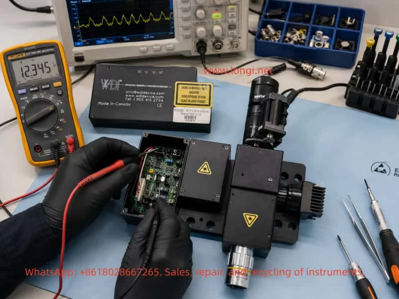
According to the equipment label:
Manufacturer: WDI Device Canada
Model: ATF5 SYS 658mm
Manufacturing Date: 08/2010
Laser Classification: Class 3B Laser Product
The device belongs to an industrial-grade laser measurement sensor equipped with a Class 3B laser source.
Class 3B laser products usually provide higher optical output power compared with ordinary industrial sensors, allowing longer measurement distances and higher measurement stability. However, they also require strict safety procedures during maintenance.
WDI ATF series sensors have been used in applications such as:
- Automated production lines;
- Steel processing equipment;
- Automotive manufacturing systems;
- CNC machines;
- Robotic positioning systems;
- Packaging inspection systems;
- Precision mechanical measurement equipment.
2. Operating Principle of Industrial Laser Displacement Sensors
Understanding the measurement principle is essential before troubleshooting.
Most industrial laser displacement sensors operate based on optical triangulation technology.
2.1 Laser Emission
Inside the sensor, a semiconductor laser diode generates a stable laser beam.
The optical system focuses the laser onto the target surface.
The laser spot is projected onto the measured object.
2.2 Reflection From Target Surface
When the laser beam reaches the object:
- Part of the light is absorbed;
- Part of the light is reflected back toward the sensor.
The reflected light carries distance information.
2.3 Optical Receiving System
The reflected laser is captured by an optical receiver.
Common receiving components include:
- CCD arrays;
- CMOS sensors;
- PSD (Position Sensitive Detector);
- APD (Avalanche Photodiode).
The receiving element detects the position of the reflected laser spot.
2.4 Signal Processing and Distance Calculation
The internal processor calculates the distance based on:
- Laser projection angle;
- Receiving position;
- Optical geometry;
- Calibration parameters.
The final output can be provided through:
- Analog signals;
- Digital communication;
- RS232/RS485 interfaces;
- Industrial communication protocols.
3. Common Failure Modes of WDI ATF5 Laser Sensors
During industrial maintenance, WDI ATF5 sensors commonly fail in several areas.
3.1 Laser Completely Not Working
Symptoms
Typical symptoms include:
- No visible laser spot;
- No distance measurement output;
- Machine controller reports measurement failure.
Many users immediately assume the laser diode is damaged. However, the actual failure may come from several different circuits.
Possible Cause 1: Laser Diode Aging or Failure
Laser diodes are consumable optical components.
After long-term operation, the laser diode may experience:
- Reduced optical output power;
- Increased threshold current;
- Weak laser intensity;
- Complete loss of emission.
For sensors manufactured around 2010, laser diode aging is a realistic possibility.
Possible Cause 2: Laser Driver Circuit Failure
The laser diode cannot be directly connected to the power supply.
It requires a dedicated driver circuit, usually including:
- Constant-current control;
- Current feedback circuit;
- Temperature compensation;
- Protection circuits.
If the laser driver fails, the laser diode may remain completely off even if the diode itself is still good.
Common failed components include:
- MOSFET transistors;
- Operational amplifiers;
- Switching regulators;
- Current sensing resistors;
- Voltage regulators.
Possible Cause 3: Internal Power Supply Failure
Industrial laser sensors usually contain multiple voltage rails:
Examples:
- +5V digital supply;
- +12V analog supply;
- Laser driver supply;
- Optical receiver bias voltage.
If internal DC/DC conversion fails, the sensor may show:
- No laser output;
- No processor operation;
- Communication failure.
3.2 Laser Works but Measurement Fails
This failure is frequently misunderstood.
A visible laser does not mean the sensor is functioning correctly.
The emission system may work while the receiving or processing system has failed.
Possible Cause 1: Optical Receiver Failure
The receiving module may fail due to:
- Strong light exposure;
- Dust contamination;
- Aging;
- Static electricity damage.
The sensor may still emit laser light but cannot calculate distance.
Possible Cause 2: Optical Window Contamination
Industrial environments often contain:
- Oil mist;
- Dust;
- Metal particles;
- Chemical contamination.
Contamination on the optical window can reduce reflected light intensity.
The result:
- Laser is visible;
- Measurement becomes unstable;
- Distance readings become incorrect.
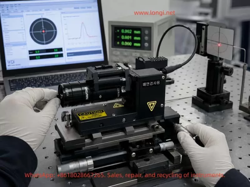
Cleaning must be performed carefully.
Ordinary paper or rough materials should not be used because optical coatings can easily be damaged.
3.3 Unstable Measurement or Signal Drift
Symptoms
The sensor operates but produces:
- Jumping values;
- Poor repeatability;
- Incorrect distance readings.
Cause 1: Unstable Laser Output
When laser power decreases:
The receiving signal becomes weak.
The internal algorithm continuously compensates, causing:
- Measurement fluctuation;
- Increased noise;
- Drift.
Cause 2: Temperature Compensation Failure
Industrial laser sensors usually include temperature compensation.
The system uses:
Temperature sensor → Compensation algorithm → Corrected output
If:
- Temperature sensor fails;
- Calibration data is lost;
- Processor malfunctions;
temperature-related measurement errors may occur.
Cause 3: Mechanical Installation Problems
Laser measurement accuracy depends heavily on mechanical alignment.
Problems such as:
- Loose mounting screws;
- Equipment vibration;
- Optical axis movement;
can create measurement errors.
4. Professional Diagnostic Procedure for WDI ATF5 Repair
When a customer reports:
“The laser is broken”
the first step should not be replacing the laser module.
A systematic inspection process is required.
Step 1: Check External Conditions
Power Supply Inspection
Measure:
- Input voltage;
- Voltage stability;
- Startup voltage behavior;
- Power ripple.
Many sensor failures are caused by:
- Incorrect voltage;
- Reverse polarity;
- Damaged industrial power supplies.
Wiring Inspection
Confirm:
- Positive and negative power connections;
- Signal wiring;
- Communication cables.
Step 2: Check Indicator Status
Observe:
- LED indicators;
- Alarm status;
- Communication status.
Different symptoms indicate different failure areas.
For example:
CPU running but laser missing
Focus on:
- Laser driver circuit;
- Laser diode.
No indicators at all
Focus on:
- Internal power supply.
Step 3: Internal Circuit Inspection
After opening the sensor, inspect key sections.
Power Supply Section
Check:
- DC/DC converter output;
- Voltage regulators;
- Electrolytic capacitors;
- Switching devices.
Aged capacitors are common problems in older industrial electronics.
Laser Driver Section
Important measurements:
- Laser supply voltage;
- Driver current;
- Feedback signal.
Special caution:
A laser diode should never be tested like a normal resistor.
Incorrect measurement methods may permanently damage the laser component.
Step 4: Determine Whether the Laser Module Is Damaged
Method 1: Measure Driver Output
If:
- Driver circuit output is normal;
- Correct current is supplied;
- Laser remains off;
the laser diode is likely damaged.
Method 2: Replace With a Compatible Module
A replacement laser module can be used for testing.
However, replacement is not simply a plug-and-play operation.
The following may require adjustment:
- Optical alignment;
- Laser power;
- Calibration parameters.
5. Major Technical Challenges During Laser Sensor Repair
5.1 Laser Module Matching
Industrial laser modules require precise specifications:
Including:
- Wavelength;
- Optical output power;
- Operating current;
- Beam divergence;
- Focal distance.
Using an incorrect replacement may cause:
- Reduced measurement range;
- Poor accuracy;
- Signal instability.
5.2 Optical Calibration
The most important part of a laser displacement sensor is not only the laser source.
It is the complete combination of:
Laser source + optical structure + calibration algorithm
After replacing optical components, recalibration is usually required.
Otherwise:
- Short distance measurement may work;
- Long distance measurement may become inaccurate.
5.3 Lack of Technical Documentation
Many older industrial sensors have problems such as:
- Manufacturer discontinued support;
- Software unavailable;
- Calibration files missing.
Repair engineers often need to rely on:
- Circuit analysis;
- Component testing;
- Comparison with working units;
- Reverse engineering techniques.
6. Common Mistakes During Repair
Mistake 1: Assuming Laser Failure Immediately
A missing laser beam does not always mean the laser diode is damaged.
Many failures are caused by:
- Power supply circuits;
- Driver circuits;
- Control electronics.
Mistake 2: Replacing Laser Diode Without Calibration
A new laser diode may not match the original optical characteristics.
Without calibration:
- Measurement accuracy cannot be guaranteed.
Mistake 3: Ignoring Environmental Factors
Some sensors recover simply after:
- Optical window cleaning;
- Connector cleaning;
- Cable inspection.
7. Testing Requirements After Repair
A repaired WDI ATF5 sensor should not only be tested for laser emission.
A complete verification procedure is required.
7.1 Laser Output Verification
Confirm:
- Stable laser emission;
- Correct beam intensity;
- No abnormal fluctuation.
7.2 Distance Accuracy Test
Test multiple measurement points.
Example:
- 100 mm;
- 300 mm;
- 500 mm;
- 658 mm.
Check:
- Linearity;
- Measurement error;
- Repeatability.
7.3 Long-Term Stability Test
Perform continuous measurement testing.
Observe:
- Data fluctuation;
- Temperature influence;
- Communication stability.
7.4 Machine Integration Test
After repair:
Install the sensor back into the machine.
Verify:
- PLC communication;
- Measurement feedback;
- Automatic control operation.
8. Economic Value of Repairing WDI ATF5 Sensors
For industrial equipment, replacement is not always the best solution.
Reason 1: Production Downtime Cost
A factory shutdown can cost much more than sensor repair.
Reason 2: Replacement Compatibility Problems
A new sensor may require:
- Mechanical modification;
- New wiring;
- Software changes;
- PLC programming updates.
Reason 3: Existing Calibration Data
The original sensor already matches:
- Machine geometry;
- Software settings;
- Control system parameters.
Repair allows the equipment to continue operating with minimal changes.
Conclusion
The WDI ATF5 SYS 658mm laser displacement sensor is an example of a high-value industrial measurement device that can often be restored despite being more than ten years old.
When facing problems such as:
- No laser output;
- Measurement failure;
- Signal instability;
- Communication errors;
engineers should avoid replacing components blindly.
A professional diagnostic process should follow:
Power inspection → Control circuit analysis → Laser driver testing → Optical system inspection → Calibration → Machine operation verification
Industrial laser sensor repair is not simply replacing damaged parts. It requires understanding the interaction between optical systems, electronic circuits, mechanical alignment, and software calibration.
Through systematic troubleshooting and professional repair methods, many discontinued industrial laser sensors can be successfully restored, reducing equipment replacement costs and improving the reliability of automation systems.