
Inovance MD200 Series General-purpose Inverter User Guide: Operation Panel, Terminal Control and Fault Troubleshooting
1. Introduction
The Inovance MD200 series is a general-purpose, high-performance current vector inverter designed primarily for controlling and regulating the speed and torque of three-phase AC asynchronous motors. Its compact book-type structure supports seamless side-by-side and DIN rail installation, making it ideal for space-constrained environments in textile, paper, wire drawing, machine tools, packaging, food processing, fans, pumps, and various automated production equipment.
This guide focuses on the practical aspects of operating the MD200 inverter, including the LED operation panel, terminal control wiring, parameter configuration, RS485 communication setup, and fault code diagnosis. The MD200 is a general-purpose inverter (not a servo drive), meaning it is optimized for basic V/f control applications and simple terminal wiring rather than high-precision motion control.
The MD200 series is available in both single-phase 220V and three-phase 380V input versions, with power ratings ranging from 0.4kW to 3.7kW. All models feature a built-in EMC filter to improve anti-interference capability and reduce conducted emissions. The inverter also supports macro parameters, allowing one-button optimization for typical industry applications such as conveyor belts and fan loads.
2. Operation Panel
The MD200 series comes equipped with a built-in LED operation panel that provides local control, parameter setting, and status monitoring capabilities. Understanding the panel layout and navigation is essential for commissioning and daily operation.
2.1 Panel Layout and Buttons
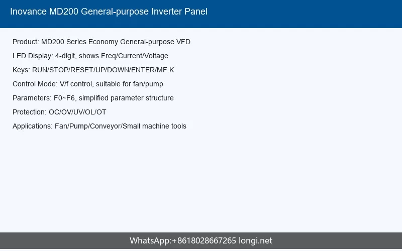
The LED operation panel includes the following keys:
- PRG: Program/Menu key. Used to enter or exit the parameter menu.
- ENTER: Confirm key. Used to confirm parameter values or enter a submenu.
- RUN: Run key. Starts the inverter in the forward direction when the command source is set to the panel.
- STOP/RES: Stop/Reset key. Stops the inverter during operation or resets a fault condition.
- MF.K: Multi-function key. Can be configured for jog operation or other custom functions.
- UP/DOWN arrows: Used to increase or decrease parameter values or navigate menus.
2.2 LED Display Indicators
The panel provides visual feedback through LED indicators:
- RUN indicator: Illuminates when the inverter is running. In transient power-loss conditions, it flashes to indicate the inverter is in “run without stop” mode.
- Command source LED: Indicates the active command channel. OFF means panel control; ON means terminal control; flashing means communication control.
2.3 Basic Panel Operations
Quick parameter lookup mode: Press PRG to enter the parameter menu. Use the UP/DOWN keys to scroll through parameter groups (F0, F1, F2, etc.), then press ENTER to access parameters within that group. After modifying a value, press ENTER again to save.
Running status display: In normal operation mode, the panel displays the current running frequency. Pressing the UP or DOWN key during operation can adjust the target frequency if the frequency source is set to digital setting.
Fault display: When a fault occurs, the panel displays the fault code (e.g., Err02, Err09). Pressing STOP/RES resets the fault if the condition has cleared.
2.4 Industry Macro Configuration
The MD200 supports industry macros for quick setup. By setting parameter FP-01, users can automatically configure optimal parameters for common applications:
- FP-01 = 20: Mechanical movement (conveyor belt) industry. Configures multi-speed, short start time, and dynamic S-curve acceleration.
- FP-01 = 21: Inertia (fan) industry. Configures analog control, reverse rotation prohibition, and speed tracking restart.
3. Terminal Control
3.1 Terminal Layout Overview
The MD200 control terminals are divided into main circuit terminals and control circuit terminals. The main circuit includes:
- L1, L2: Single-phase AC power input (for single-phase models)
- R, S, T: Three-phase AC power input (for three-phase models)
- U, V, W: Three-phase motor output
- B: Braking resistor connection terminal
- PE: Ground terminal (must be securely connected)
3.2 Control Circuit Terminals
The control circuit provides the following terminals for external control and monitoring:
| Terminal | Name | Function |
|---|---|---|
| DI1~DI4 | Digital Input | Multi-function input terminals. DI1~DI3 are low-speed inputs (<100Hz). DI4 can also serve as high-speed pulse input (up to 20kHz) or as DO output on MD200XXX models. |
| DIO | Digital Input/Output | Available only on MD200XXX-NC models. Can be configured as DI (high-speed pulse input up to 20kHz) or DO via DIP switch. |
| COM | 24V Ground | Common ground for digital I/O, internally isolated from GND. |
| +10V | Reference Voltage | 10V analog output, max 10mA. |
| GND | Analog Ground | Analog signal ground, internally isolated from COM. |
| AI | Analog Input | 0~10V or 0~20mA input, 12-bit resolution, accuracy 0.5%, response time <8ms. |
| AO | Analog Output | 0~10V output, 10-bit resolution, accuracy 1%. |
| TA-TC / TA-TB | Relay Output | TA-TC: normally open; TA-TB: normally closed. Contact rating: 3A/250VAC, 3A/30VDC. |
| 485+, 485- | RS485 | Half-duplex RS485 communication, baud rates up to 115200bps, supporting up to 64 nodes. |
3.3 Wiring Modes for Digital Inputs
MD200XXX Models (NPN/Sinking only): These models only support NPN (sinking) wiring. In this configuration, the COM terminal connects to the positive side of the external power supply, and the switch connects between the DI terminal and COM. When the switch closes, the DI terminal is pulled low (<5V), activating the input.
MD200XXX-NC Models (NPN/PNP selectable): These models support both NPN and PNP wiring, selectable via DIP switches. The PNP (sourcing) mode connects the COM terminal to the negative side of the external power supply, and the switch connects between the positive supply and the DI terminal.
3.4 Common Terminal Control Wiring
Two-wire mode 1 (F4-11=0): The most commonly used mode. DI1 is assigned as forward run (FWD), and DI2 as reverse run (REV). Closing SW1 while SW2 is open causes forward rotation; closing SW2 while SW1 is open causes reverse rotation. If both switches are open or both closed, the motor stops.
Two-wire mode 2 (F4-11=1): DI1 serves as the run enable command, and DI2 as the direction command. When SW1 is closed, the inverter is enabled. SW2 open = forward; SW2 closed = reverse. If SW1 is open, the motor does not run regardless of SW2 state.
Three-wire mode 1 (F4-11=2): DI3 serves as the three-wire run control (typically a normally closed stop button), DI1 as forward run, and DI2 as reverse run. The stop button (SW3) must remain closed for operation. Pressing SW1 starts forward rotation; pressing SW2 starts reverse rotation. Releasing SW3 stops the inverter immediately.
3.5 Analog Input Wiring
The AI terminal accepts either 0~10V voltage signals or 0~20mA current signals. Because analog signals are susceptible to external interference, shielded cables are mandatory. The wiring distance should not exceed 20 meters. In high-interference environments, add filter capacitors or ferrite cores on the signal source side. The +10V terminal provides the reference voltage for potentiometer-based speed control.
4. Parameters
The MD200 organizes parameters into functional groups. For general-purpose V/f control applications, the following parameters are most critical during commissioning.
4.1 F0 Group: Basic Functions
| Parameter | Function | Default | Description |
|---|---|---|---|
| F0-01 | Motor Control Mode | 0 | 0=SVC (for 3-phase models), 2=V/F control. Select V/F for general-purpose or multi-motor applications. |
| F0-02 | Command Source | 0 | 0=Panel, 1=Terminal, 2=Communication. |
| F0-03 | Main Frequency Source | 0 | 0=Digital (non-volatile), 2=AI1, 6=Multi-speed, 8=PID, 9=Communication. |
| F0-08 | Preset Frequency | 50.00Hz | Target frequency for digital setting mode. |
| F0-10 | Max Frequency | 50.00Hz | Upper limit of output frequency (50~500Hz). |
| F0-12 | Upper Frequency | 50.00Hz | Maximum allowed running frequency. |
| F0-14 | Lower Frequency | 0.00Hz | Minimum allowed running frequency. |
| F0-15 | Carrier Frequency | 6.0kHz | Range 0.5~16kHz. Higher values improve current waveform but increase heat. |
| F0-17 | Acceleration Time 1 | 0.0s | Time from 0 to F0-25 (acceleration reference frequency). |
| F0-18 | Deceleration Time 1 | 0.0s | Time from F0-25 to 0 frequency. |
4.2 F1 Group: Motor Parameters
Accurate motor parameter entry is essential for good control performance. Key parameters include:
- F1-01: Motor rated power (kW)
- F1-02: Motor rated voltage (V)
- F1-03: Motor rated current (A)
- F1-04: Motor rated frequency (Hz), typically 50Hz
- F1-05: Motor rated speed (rpm)
For vector control mode (SVC), additional motor parameters (F1-06 through F1-10) can be obtained automatically through the motor auto-tuning process (F1-37). For V/f control, the basic five parameters above are sufficient.
4.3 F3 Group: V/F Control Parameters
When F0-01=2 (V/F control), the following parameters affect performance:
| Parameter | Function | Default | Description |
|---|---|---|---|
| F3-00 | V/F Curve Setting | 0 | 0=Linear V/F, 1=Multi-point V/F. Use linear for general loads. |
| F3-01 | Torque Boost | Model-dependent | Auto or manual torque boost (0.1%~30.0%). Higher values help with heavy starting loads. |
| F3-18 | Overcurrent Stall Current | 150% | When output current exceeds this percentage of rated current, the inverter reduces frequency to prevent tripping. |
| F3-19 | Overcurrent Stall Enable | 1 | 0=Disabled, 1=Enabled. Enable for applications with high inertia. |
| F3-22 | Overvoltage Stall Voltage | 770V | DC bus voltage threshold for overvoltage stall protection. |
| F3-23 | Overvoltage Stall Enable | 1 | Should be set to 0 when using a braking resistor to avoid extended deceleration. |
4.4 F4 Group: Input Terminals
Parameters F4-00 through F4-04 define the function of each digital input terminal. Common function assignments include:
- 0: No function
- 1: Forward run (FWD)
- 2: Reverse run (REV)
- 3: Three-wire run control
- 7: Fault reset
- 12: Multi-speed terminal 1
- 13: Multi-speed terminal 2
- 18: Frequency source switch
Parameter F4-11 selects the terminal command mode: 0=Two-wire 1, 1=Two-wire 2, 2=Three-wire 1, 3=Three-wire 2.
5. Communication
The MD200 series provides RS485 communication interface supporting the Modbus-RTU protocol, enabling centralized control from a PC or PLC. This section covers the essential configuration for communication-based control and monitoring.
5.1 Hardware Connection
The 485+ and 485- terminals form a half-duplex RS485 bus. The communication cable should use twisted-pair shielded wire with the shield connected to ground at one end only. The maximum baud rate is 115200bps, and the network supports up to 64 nodes. The total bus length should not exceed 1200 meters at lower baud rates.
5.2 FD Group: Communication Parameters
| Parameter | Function | Default | Description |
|---|---|---|---|
| FD-00 | Baud Rate | 5 (9600bps) | Ones digit sets Modbus baud: 0=300bps, 5=9600bps, 9=115200bps. |
| FD-01 | Modbus Data Format | 0 | 0=No parity (8-N-2), 1=Even parity (8-E-1), 2=Odd parity (8-O-1). |
| FD-02 | Local Address | 1 | Range 0~247. Address 0 is broadcast. Each node must have a unique address. |
| FD-03 | Response Delay | 2ms | Delay from receiving a request to sending a response. |
| FD-04 | Communication Timeout | 0.0s | If the interval between messages exceeds this value, Err16 (communication fault) is triggered. Set to 0 to disable. |
| FD-05 | Protocol Selection | 1 | 0=Non-standard Modbus, 1=Standard Modbus. Use standard Modbus for new designs. |
5.3 Modbus Communication Basics
The MD200 implements Modbus-RTU slave protocol. It supports two function codes: 0x03 (read holding registers) and 0x06 (write single register). Word-type parameters only are supported; byte or bit operations are not available.
Parameter addressing: The communication address for parameter F0-16 is 0xF010, where the high byte (F0) represents the parameter group and the low byte (10) is the parameter index in hexadecimal. For A-group parameters, use the same rule (e.g., AC-08 = 0xAC08).
Control commands: Write to address 0x2000 to control the inverter remotely:
- 0x0001: Forward run
- 0x0002: Reverse run
- 0x0003: Forward jog
- 0x0004: Reverse jog
- 0x0005: Coast to stop
- 0x0006: Deceleration stop
- 0x0007: Fault reset
Communication frequency setting: Write to address 0x1000. The value range is -10000 to +10000, corresponding to -100.00% to +100.00% of maximum frequency (F0-10). For example, if F0-10=50Hz and you write 8000 (decimal), the actual frequency is 50 * 80.00% = 40Hz.
5.4 Non-Parameter Data Access
The inverter also provides read-only status data via Modbus:
- 0x3000: Running status (1=forward, 2=reverse, 3=stopped)
- 0x8000: Current fault code (see fault code table)
- 0x1001: Running frequency
- 0x1002: DC bus voltage
- 0x1004: Output current
- 0x1005: Output power
6. Fault Codes
The MD200 provides 25 alarm and protection functions. When a fault occurs, the inverter stops output, the fault relay activates, and the fault code displays on the LED panel. Understanding these codes enables rapid diagnosis and recovery.
6.1 Fault Code Reference Table
| Fault Code | Name | Probable Cause | Remedy |
|---|---|---|---|
| Err02 | Overcurrent during acceleration | Short circuit in output; acceleration time too short; V/F curve improper; voltage too low; starting a rotating motor. | Check wiring; increase accel time; adjust V/F curve; ensure voltage is normal; use speed tracking restart. |
| Err03 | Overcurrent during deceleration | Short circuit; deceleration time too short; no braking resistor installed. | Check wiring; increase decel time; install or replace braking resistor. |
| Err04 | Overcurrent at constant speed | Short circuit; sudden load increase; inverter undersized. | Check wiring; eliminate sudden load; select larger inverter. |
| Err05 | Overvoltage during acceleration | Input voltage too high; external force driving motor during accel. | Reduce input voltage; remove external force or install braking resistor. |
| Err06 | Overvoltage during deceleration | Input voltage too high; deceleration time too short. | Reduce input voltage; increase decel time; install braking resistor. |
| Err07 | Overvoltage at constant speed | Input voltage too high; external force driving motor. | Reduce input voltage; remove external force or add braking resistor. |
| Err08 | Control power fault | Input voltage outside specification. | Adjust voltage to within specification. |
| Err09 | Undervoltage | Instantaneous power loss; input voltage low; abnormal DC bus. | Reset fault; adjust voltage; contact technical support if internal. |
| Err10 | Inverter overload | Load too heavy or motor stalled; inverter undersized. | Reduce load; check mechanical system; select larger inverter. |
| Err11 | Motor overload | Improper F9-01 setting; load too heavy; inverter undersized. | Adjust F9-01 correctly; reduce load; select larger inverter. |
| Err12 | Input phase loss | Abnormal three-phase input; drive board fault. | Check input wiring; contact technical support for internal faults. |
| Err13 | Output phase loss | Disconnected motor leads; unbalanced output; module fault. | Check motor wiring and windings; contact technical support. |
| Err14 | Inverter overheating | Ambient temp >75C; blocked air duct; damaged fan or thermistor. | Lower ambient temperature; clean air duct; replace unit if hardware failed. |
| Err15 | External fault | External fault signal received via DI or virtual IO. | Remove external fault source and reset. |
| Err16 | Communication fault | Host abnormal; communication line fault; FD parameters incorrect. | Check host and cable; verify FD group settings. |
| Err18 | Current detection fault | Drive board hardware fault. | Replace the inverter unit. |
| Err19 | Motor tuning fault | Motor parameters not set according to nameplate; tuning timeout. | Enter motor nameplate data correctly; check motor wiring. |
| Err21 | EEPROM fault | EEPROM chip damaged. | Replace the inverter unit. |
| Err23 | Output ground short | Motor shorted to ground; damaged IGBT. | Replace motor cable or motor; replace inverter. |
| Err26 | Total run time reached | Cumulative run time exceeded preset value. | Use parameter initialization to clear. |
| Err27/28 | User-defined fault 1/2 | User-defined fault signal received via DI or virtual IO. | Remove fault source and reset. |
| Err30 | Load loss fault | Output current below F9-64 setting. | Confirm load is connected; adjust F9-64/65 settings. |
| Err31 | PID feedback loss | PID feedback below FA-26 threshold. | Check feedback signal; set FA-26 to appropriate value. |
| Err40 | Current limit fault | Load too heavy; inverter undersized. | Reduce load; select larger inverter. |
| Err42 | Speed deviation fault | Motor stall; improper F9-69/70 settings; wiring fault. | Check mechanics; verify motor tuning; adjust detection parameters. |
6.2 Common Fault Scenarios and Quick Solutions
No display after power-on: Check input power voltage. If voltage is normal but display remains blank, the unit may be damaged and requires replacement.
Frequent Err14 (overheating): Reduce the carrier frequency (F0-15). Check if the cooling fan is running and whether the air duct is blocked by dust. Ensure ambient temperature is within -10C to 50C.
Motor does not rotate after running command: Verify wiring between inverter and motor. Check that motor parameters (F1 group) are correctly entered. Confirm that the command source (F0-02) matches the actual control method being used.
Frequent overcurrent/overvoltage trips: Verify motor parameters are correct. Increase acceleration/deceleration times (F0-17/18). If using a braking resistor, set F3-23 (overvoltage stall enable) to 0 to avoid extended deceleration. Check for mechanical load fluctuations.
DI terminals not responding: Verify F4 group parameter settings for the terminal functions. Check external signal wiring. For NPN wiring, ensure COM is connected correctly. For multi-inverter installations, ensure isolation diodes are in place.
6.3 Fault Reset Procedures
Most faults can be reset by pressing the STOP/RES key on the operation panel. For remote systems, send Modbus command 0x0007 to address 0x2000. Alternatively, a momentary power cycle will clear most non-hardware faults. If a fault persists after reset, inspect the wiring and parameter settings before contacting technical support.
For hardware-related faults (Err18, Err21, Err23), replacement of the inverter unit is typically required. For Err12 and Err13 (phase loss), first eliminate external wiring issues before assuming internal damage.
This guide is based on the Inovance MD200 Series General-purpose Inverter User Manual (Version C03, 2023). For complete parameter listings, advanced functions, and detailed wiring diagrams, please refer to the official PDF manual available from Inovance Technical Support.