
Introduction
The Siemens SINAMICS S120 drive system is widely used in high-performance industrial applications such as CNC machine tools, robotics, packaging systems, printing equipment, metallurgy production lines, and complex automation platforms. Compared with standard frequency converters, the SINAMICS S120 adopts a highly modular architecture, providing excellent flexibility and performance.
However, the advanced structure of the S120 also makes troubleshooting more complex. Many engineers tend to interpret fault messages literally. When they see:
- F30025 – Power unit overtemperature
- F00004 – Drive overtemperature
their first assumption is usually:
- The cabinet temperature is too high.
- The cooling fan has failed.
- The heat sink is overheating.
- The drive has insufficient ventilation.
In many real-world repair cases, however, a very different situation occurs:
The drive reports an overtemperature fault immediately after power-up, even though the Motor Module is completely cold and has not had any opportunity to generate heat.
This situation appears contradictory:
- The system reports an overheating condition.
- The drive temperature is normal.
- The cooling system is working.
- The parameter temperature reading looks normal.
- The fault cannot be reset.
The actual problem is often not a real thermal overload, but rather:
An abnormal temperature detection circuit, internal power unit fault, or Motor Module hardware failure causing the SINAMICS protection system to trigger an overtemperature alarm.
This article explains the fault mechanism, diagnostic process, differences between CU320 and Motor Module faults, and practical troubleshooting methods for SINAMICS S120 F30025/F00004 alarms.
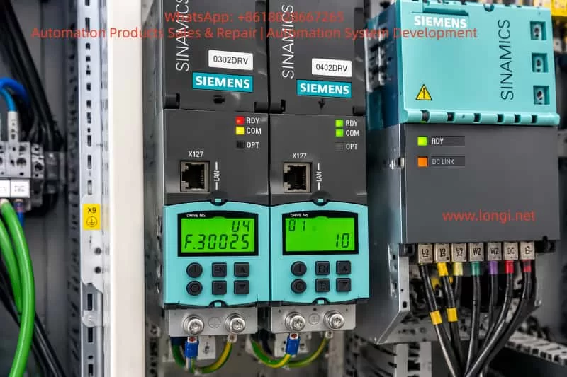
1. Understanding the SINAMICS S120 System Architecture
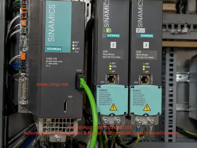
Before analyzing F30025, it is important to understand the hardware structure of SINAMICS S120.
Unlike a conventional inverter where the control and power section are integrated into one unit, the SINAMICS S120 uses a modular design.
A typical structure is:
              PLC / Controller
                    |
                    |
                CU320-2 PN
             (Control Unit)
                    |
                DRIVE-CLiQ
                    |
        ---------------------------
        |                         |
   Motor Module              Motor Module
        |                         |
      Motor 1                 Motor 2
The two main parts are:
1.1 CU320 Control Unit
The CU320-2 PN is responsible for:
- Motion control
- Parameter management
- Communication
- DRIVE-CLiQ network management
- Topology identification
- Fault processing
A typical model:
6SL3040-1MA01-0AA0
SINAMICS CU320-2 PN
The CU320 can be considered the “brain” of the SINAMICS system.
However, it does not directly drive the motor power stage.
1.2 Motor Module / Power Unit
The Motor Module performs the actual high-power functions:
- IGBT switching
- Motor current control
- Voltage measurement
- Current measurement
- Power semiconductor protection
- Temperature monitoring
Most F30025 faults originate from this section.
This means:
The fault is displayed by the CU320, but the actual fault source is usually inside the Motor Module.
2. What Does SINAMICS S120 F30025 Really Mean?
F30025 – Power unit overtemperature
Siemens defines F30025 as:
Power unit: Overtemperature
Many engineers interpret this as:
“The drive temperature is physically too high.”
However, this is incomplete.
SINAMICS monitors multiple temperature points, including:
- Heat sink temperature
- IGBT module temperature
- Semiconductor junction temperature
- Internal electronic board temperature
The most important value is often:
IGBT Junction Temperature
The temperature inside an IGBT chip can be significantly higher than the temperature measured on the outside of the drive.
For example:
Heat sink surface:
40°C
while internally:
IGBT junction temperature > protection limit
This is possible because heat must travel through several thermal layers:
IGBT chip
    |
Silicon layer
    |
Solder layer
    |
Base plate
    |
Heat sink
Every layer introduces thermal resistance.
Therefore:
A normal external temperature does not always mean the internal semiconductor temperature is normal.
3. Understanding F00004 Drive Overtemperature Fault
Another common SINAMICS alarm is:
F00004 – Drive overtemperature
This fault generally relates to:
- Power unit temperature monitoring
- Cooling system problems
- Temperature feedback abnormalities
When F30025 and F00004 appear together, the system believes that the power section temperature protection has been activated.
However, the key question is:
Is the drive actually hot?
4. The Most Important Diagnostic Clue: Fault Appears Immediately After Power-Up
This is the most valuable diagnostic information.
A typical real overheating fault follows this sequence:
Drive starts
      |
Motor operates
      |
Power loss generates heat
      |
Temperature rises
      |
Protection activates
This process normally takes:
- several seconds,
- minutes,
- or longer depending on load.
However, if the fault appears:
- immediately after power-on,
- before motor operation,
- while the cabinet is cold,
then the situation is different.
The likely sequence becomes:
Temperature detection signal abnormal
              |
              |
Controller interprets high temperature
              |
              |
F30025/F00004 protection triggered
In this situation, the system is not detecting real heat.
It is detecting an abnormal temperature signal.
5. Why Engineers Often Suspect the CU320
Because the CU320 is connected to everything, many technicians initially suspect it.
The reasoning is usually:
“The fault appears on the control panel, so the control unit must be bad.”
However, this is a common misunderstanding.
A useful comparison is a car:
If the dashboard shows:
“Engine temperature too high”
the dashboard itself is not necessarily defective.
The problem may be:
- engine sensor,
- wiring,
- ECU,
- cooling system.
SINAMICS works similarly:
Motor Module
      |
Temperature sensor
      |
Power electronics
      |
DRIVE-CLiQ
      |
CU320
      |
Fault displayed
The display location is not the same as the fault location.
6. How to Determine CU320 Fault or Motor Module Fault
Method 1: Check When the Fault Appears
Case A:
Fault appears immediately after power-up.
Most likely:
- Motor Module temperature sensing failure
- Power unit electronics fault
- Internal communication problem
Case B:
Fault appears after running.
Check:
- Cooling fan
- Air filter
- Cabinet temperature
- Motor load
- PWM frequency
7. Using Temperature Parameters for Diagnosis
SINAMICS provides temperature monitoring parameters.
One commonly checked parameter is:
r0037
Power unit temperature
Example:
Faulty drive:
30°C
Healthy drive:
30°C
This indicates:
- Ambient temperature is normal.
- The temperature feedback value is not obviously abnormal.
However, engineers should be careful:
A normal r0037 value does not completely eliminate a temperature sensing problem.
Because:
Different sensors may exist:
- Heat sink temperature sensor
- IGBT junction temperature calculation
- Internal protection sensor
A possible situation is:
Heat sink temperature normal

        ↓

IGBT temperature sensing abnormal

        ↓

F30025 triggered
8. Why Replacing the CU320 Usually Does Not Solve F30025
The CU320 manages:
- Control
- Communication
- Parameters
It does not contain:
- IGBT modules
- Power transistors
- Heat sink sensors
- Power temperature circuits
If the Motor Module has:
- failed NTC sensor,
- damaged temperature sampling circuit,
- power board problem,
replacing the CU320 will not correct the fault.
The correct troubleshooting order is usually:
- Verify CU320 communication.
- Confirm fault source.
- Inspect Motor Module.
- Repair or replace the power unit.
9. Possible Internal Failures Inside the Motor Module
9.1 Temperature Sensor (NTC) Failure
The most common cause.
NTC sensors work by changing resistance according to temperature.
Typical failures:
- Open circuit
- Short circuit
- Resistance drift
If the signal becomes incorrect:
The controller may interpret it as:
“Temperature too high.”
9.2 Temperature Sampling Circuit Failure
The temperature signal path may include:
- Amplifiers
- Filtering circuits
- ADC inputs
- Protection comparators
Example:
Normal:
NTC sensor
     |
Voltage change
     |
ADC conversion
     |
Controller
Fault:
ADC input abnormal

     |

Controller sees overtemperature

     |

F30025
9.3 Aging of Power Electronics
Long-term operation can cause:
- Capacitor degradation
- Solder fatigue
- Thermal cycling damage
- PCB aging
Applications with frequent acceleration/deceleration are especially demanding.
Examples:
- CNC machines
- Press machines
- Hoists
- High-speed equipment
9.4 IGBT Module Problems
IGBT aging may cause:
- Increased conduction losses
- Higher heat generation
- Abnormal thermal behavior
However:
If the alarm occurs immediately after power-up, a pure IGBT overheating problem is less likely.
10. Recommended Troubleshooting Procedure
For SINAMICS S120 F30025/F00004 faults, the recommended procedure is:
Step 1: Confirm Fault Timing
Record:
- Immediate after power-on?
- After motor operation?
- Under heavy load?
Step 2: Check Cooling System
Verify:
- Cooling fans
- Air filters
- Cabinet ventilation
- Ambient temperature
Step 3: Use Siemens Diagnostic Software
The most effective tools are:
- Siemens Startdrive
- TIA Portal
- STARTER
Check:
- Fault history
- Fault value
- Component number
- Drive object
The most important information is:
Which drive object generated the fault?
Step 4: Compare with a Healthy Module
If multiple Motor Modules exist:
Compare:
- Temperature values
- Current values
- Status information
- Diagnostic data
Step 5: Decide Repair or Replacement
If the Motor Module is expensive:
Repair evaluation may be worthwhile.
Possible repair areas:
- Temperature sensing circuit
- Power interface board
- Driver board
- Internal electronics
11. Common Troubleshooting Mistakes
Mistake 1: Trusting the Fault Name Literally
Seeing:
“Overtemperature”
does not always mean:
“High temperature exists.”
Industrial fault messages describe the protection condition, not always the physical cause.
Mistake 2: Replacing CU320 First
Because CU320 displays the fault, technicians sometimes replace it first.
However:
For F30025:
The Motor Module should normally be investigated first.
Mistake 3: Working Without Siemens Software
The BOP display provides only limited information.
SINAMICS S120 is designed to be diagnosed through:
- Startdrive
- TIA Portal
- STARTER
Without software:
Important information is hidden.
12. Practical Case Summary
A typical real case:
A Siemens SINAMICS S120 system reported:
F30025
Power unit overtemperature

F00004
Drive overtemperature
The operator checked:
- Cabinet temperature normal
- Cooling system normal
- Drive was cold
- Temperature parameter approximately 30°C
The faults appeared immediately after power-up.
Initial suspicion:
CU320 control unit.
After further diagnosis:
The problem was confirmed to be related to the Motor Module, not the CU320.
The final conclusion:
The Motor Module had an internal power unit temperature monitoring problem.
13. Final Conclusion
SINAMICS S120 F30025 and F00004 faults require careful analysis.
The most important diagnostic rule is:
The location where the fault is displayed is not necessarily the location where the fault occurs.
For a normal overheating condition:
- Temperature rises gradually.
- Load operation causes the fault.
- Cooling problems are involved.
For a false overtemperature alarm:
- Fault appears immediately.
- Drive is still cold.
- Temperature values appear normal.
- Motor Module internal diagnostics become the focus.
When F30025/F00004 occurs immediately after startup, engineers should prioritize inspection of:
- Motor Module temperature sensing circuits
- Power unit electronics
- Internal protection circuits
- DRIVE-CLiQ communication
Understanding the architecture of SINAMICS S120 allows technicians to avoid unnecessary replacement of expensive components such as CU320 controllers and quickly locate the true fault source.
For high-value industrial drives, accurate diagnosis is often more valuable than simply replacing parts. A systematic troubleshooting approach can significantly reduce downtime, repair costs, and production losses.