
GSK DAD08A Dual-Axis Servo Drive Manual Guide: Dual-Axis Wiring, Single-Axis JOG, Electronic Gear, Parameter Backup, Alarm Isolation and Repair
DAD08A Service Focus
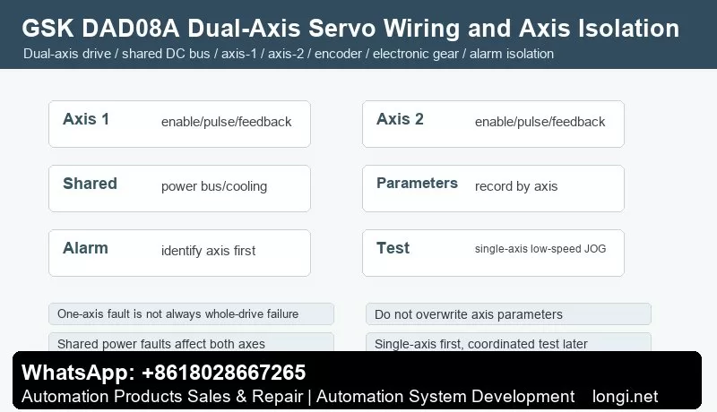
GSK DAD08A is a dual-axis servo drive used on CNC machines, feeding units and compact automation systems. Unlike single-axis DA98 drives, one drive manages two servo motors. The axes may share power bus, cooling and protection, but command signals, encoder feedback, electronic gear and tuning must be handled per axis.
Do not judge the whole drive as failed before identifying whether the alarm belongs to axis 1, axis 2 or a shared power/cooling section.
Wiring Check
Check main power, grounding, braking resistor, fan and cooling path first. Label motor cables, brake cables and encoder cables as axis 1 and axis 2. If motor or encoder plugs are swapped, one axis may run while the other alarms, or both directions become confusing.
Return ALM, SRDY and COIN signals separately to CNC or PLC whenever possible. A single common alarm makes troubleshooting slower.
Single-Axis JOG First
Do not run coordinated programs first. Move axes to a safe position, enable axis 1 only, run low-speed JOG or low-frequency pulse, then test axis 2 in the same way. Only after both axes run stably should coordinated motion be restored.
If one axis alarms, swap motor and encoder cables carefully for a short low-speed test. If the fault follows the motor, check motor and encoder. If it stays on the same channel, check the drive channel, terminals or parameters.
Electronic Gear and Parameters
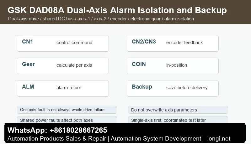
Each axis may have different screw pitch, reduction ratio and mechanical direction. Calculate electronic gear separately for each axis. Use a fixed pulse test to measure actual movement. Proportional size error points to electronic gear. Bidirectional error points to backlash or coupling.
Record parameters per axis: control mode, pulse format, direction, electronic gear, speed limit, ramp time, position gain, speed gain, torque limit, in-position window and alarm output logic. Execute parameter write/save before delivery.
Alarm Isolation
Single-axis faults include encoder open circuit, Z phase error, UVW feedback error, following error, overload, direction error and in-position failure. Check the matching encoder cable, motor cable, load and axis parameters.
Shared faults include main power abnormality, DC bus over/undervoltage, cooling fault, braking resistor fault and control power fault. These usually stop both axes.
Coordinated-motion faults occur when single-axis tests are normal but synchronized motion alarms. Check controller pulse frequency, acceleration, mechanical interference and load inertia.
Delivery Flow
Record parameters and wire numbers, confirm motor/encoder matching, check shared power and cooling, JOG axis 1, JOG axis 2, set electronic gear per axis, tune gains per axis, run coordinated low-speed test, verify ALM/SRDY/COIN returns, save parameters and run full load cycle.