
GSK DA98A/DA98D AC Servo Drive Manual Guide: Replacement Matching, Panel JOG, Parameter Save, Electronic Gear, Encoder and Alarm Repair
DA98A/DA98D Maintenance Focus
GSK DA98A and DA98D are later members of the DA98 AC servo drive family. They are used on CNC lathes, milling machines, grinders, feed axes and automatic positioning mechanisms. They share the same service logic as DA98, but replacement requires more attention to motor model, encoder type, firmware/version differences and EEPROM data.
Do not replace only by power rating. Record original parameters and motor nameplate first. The common mistakes are wrong motor-encoder matching, forgetting EEPROM write after parameter changes and misjudging mechanical jam or encoder contact failure as drive failure.
Panel Startup and JOG
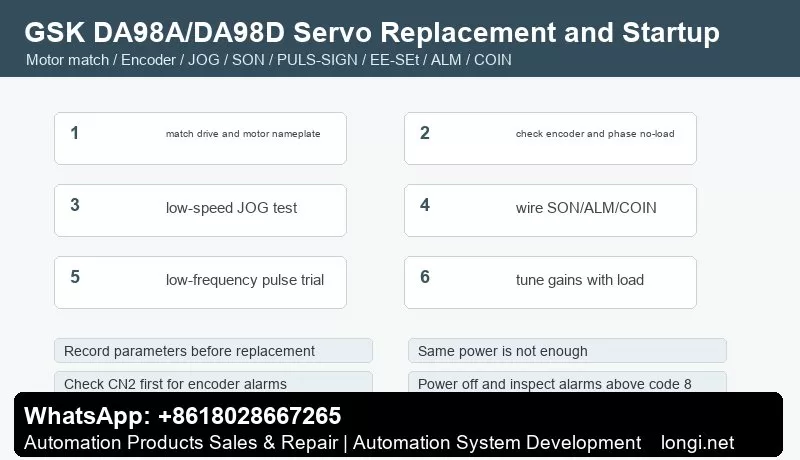
Before power on, check main power, grounding, U/V/W motor cable, braking resistor, CN1 control signals, CN2 encoder cable and shield. On first power up, do not enable SON immediately. Check display and alarm code first.
If there is no alarm, use JOG or low-speed trial run with the axis in a safe position. Verify direction, noise, current and encoder feedback. If the motor vibrates or alarms immediately, check phase order, encoder cable, coupling and load inertia before tuning gains.
CN1 Control Logic
CN1 usually exchanges SON enable, ALRS reset, drive inhibit, deviation clear, PULS/SIGN or dual pulse input, SRDY ready, ALM alarm and COIN in-position signals. At minimum, ALM and SRDY should return to CNC or PLC so the controller knows whether the servo is really ready.
If the axis does not move, check CNC pulse output, SON state, ALM, drive inhibit, pulse inhibit, electronic gear ratio and COIN conditions. If direction is reversed, change one location only; do not change CNC parameter, motor phase and drive direction at the same time.
CN2 Encoder and Motor Matching
CN2 carries encoder feedback. Encoder alarms, Z phase loss, UVW error and count error often come from loose connector, backed-out pin, broken shield, 5 V drop or encoder failure. Check cable and feedback first before replacing the drive.
After replacing drive or motor, confirm motor model parameter, encoder line count and feedback direction. Wrong matching may still allow JOG but cause positioning error, crawling, overcurrent or overheating.
Electronic Gear and Position Control
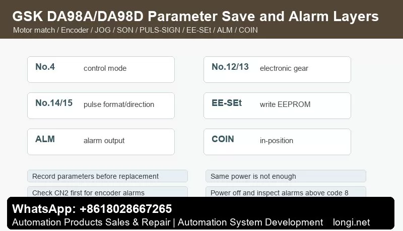
In position mode, electronic gear ratio defines mechanical movement per CNC pulse. No.12 and No.13 are commonly used as numerator and denominator, while No.14 and No.15 set pulse format and direction. Proportional size error points to electronic gear error. Bidirectional inconsistency points to backlash or mechanical issues.
Use a fixed low-frequency pulse test, measure actual movement, calculate No.12/No.13 and then verify with low-speed G01/G00 movement. Do not hide electronic gear error by changing tool offset or error window.
EEPROM Parameter Save
After changing control mode, electronic gear, pulse direction, JOG speed, speed/position gains, torque limit and related parameters, execute EE-SEt to write EEPROM. Otherwise the drive may revert after power-off.
Before replacement delivery, record control mode, pulse input type, electronic gear, maximum speed, acceleration/deceleration time, speed PI, position gain, feedforward, torque limit, alarm output logic and in-position window.
Speed Mode and Torque Limit
Some DA98A/DA98D applications use speed mode rather than pulse position mode. Check mode, speed command, forward/reverse start, maximum speed, ramp time and speed-arrival output. For torque-limit issues, check external limit input, parameter limit, load and motor current.
If no-load test is normal but load operation alarms, check guide lubrication, ball screw bearing, coupling alignment and load inertia. Parameters cannot repair a jammed machine.
Alarm Layers
Power and main-circuit alarms: check input voltage, braking resistor, DC bus capacitor, power module, contactor and grounding. Overvoltage during deceleration often relates to braking energy, inertia or too short deceleration time.
Encoder alarms: check CN2 cable, connector, shield, 5 V supply and encoder before replacing the drive.
Following error: check electronic gear ratio, command frequency, position gain, mechanical jam, backlash and inertia.
Overcurrent, overload and overheating: check motor phase cable, load jam, ramp time, speed gain, fan cooling and motor insulation. Hard alarms that cannot be cleared by ALRS require power-off inspection.
Recommended Commissioning Flow
Record original parameters and nameplates, confirm motor and encoder matching, power up without alarm, use low-speed JOG, wire CN1 basic signals, calculate electronic gear, test low-frequency pulse movement, tune gains and torque limits, execute EE-SEt and finally verify positioning accuracy under load.