
GSK DA98 AC Servo Drive Manual Guide: CN1/CN2 Wiring, Position Pulse Control, Speed Control, Electronic Gear Ratio, EEPROM Write and Alarm Repair
DA98 Is a Classic Digital AC Servo for CNC Retrofits
GSK DA98 is an early full-digital AC servo drive widely used on CNC machines, printing machinery, textile machinery and automation lines. Compared with a stepper system, DA98 uses encoder feedback from the servo motor and forms a semi-closed loop inside the drive.
For service work, do not only ask whether the motor rotates. Check control mode, CN1 command signals, CN2 encoder feedback, electronic gear ratio, gains and alarm output together. In position mode the CNC sends pulse and direction; in speed mode DA98 uses speed selection or speed command; in both modes SON enable and encoder feedback are essential.
Installation and Wiring Checks
The manual notes that DA98 default parameters may match only specific STZ motors. If another motor is used, factory parameters may be stored in the EEPROM backup area. Do not restore default parameters blindly. Confirm drive model, motor model and parameter No.1 first.
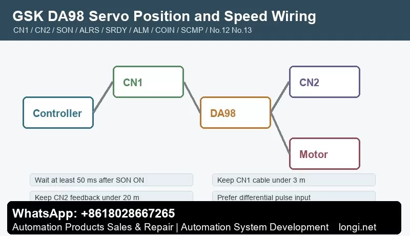
Before wiring or inspection, cut power and wait at least five minutes. Use proper grounding. Keep CN1 control cable under 3 m and CN2 feedback cable under 20 m. Use shielded cable, connect shield to FG and keep signal cables away from motor power cable, contactor coils and braking circuits.
CN1 Control Signals
CN1 includes COM+, SON servo enable, ALRS alarm reset, FSTP/RSTP drive inhibit, CLE deviation counter clear, SC1/SC2 internal speed selection, INH pulse inhibit, FIL/RIL torque limit, SRDY servo ready, ALM servo alarm, COIN in-position, SCMP speed arrival, PULS/SIGN command pulse and encoder Z output.
Commission in layers. First power, motor and encoder. Then enable SON and wait at least 50 ms before command input. Then connect SRDY and ALM to CNC or PLC. Finally test PULS/SIGN, COIN, SCMP, limits and torque-limit inputs. ALRS cannot clear all alarms; alarms above code 8 normally require power-off service.
CN2 Encoder Feedback
CN2 carries motor encoder supply and A/B/Z/U/V/W signals. The manual describes a 2500-line encoder, internally multiplied to 10000 pulses per revolution. Encoder supply, shield, pin order and cable length strongly affect stability.
For encoder alarms, do not change gains first. Check 5 V supply, cable length, A/B/Z/U/V/W wiring, shield and connector. Z-pulse loss, UVW error, encoder count error and zero-point error usually point to cable, connector, encoder or drive-interface problems.
Position Pulse Control
DA98 accepts position command pulses through CN1. Supported pulse formats include pulse plus direction, CCW/CW pulse train and two-phase quadrature pulse. Parameter No.14 sets pulse input format and No.15 reverses command direction. Differential pulse input is preferred; single-ended input lowers noise immunity and allowable frequency.
If axis direction is wrong, decide whether the cause is CNC direction, No.15, motor phase or mechanics. Do not change several places at once. If the axis does not respond, check INH, SON, FSTP/RSTP, ALM and whether PULS/SIGN actually reaches CN1.
Electronic Gear Ratio: No.12 and No.13
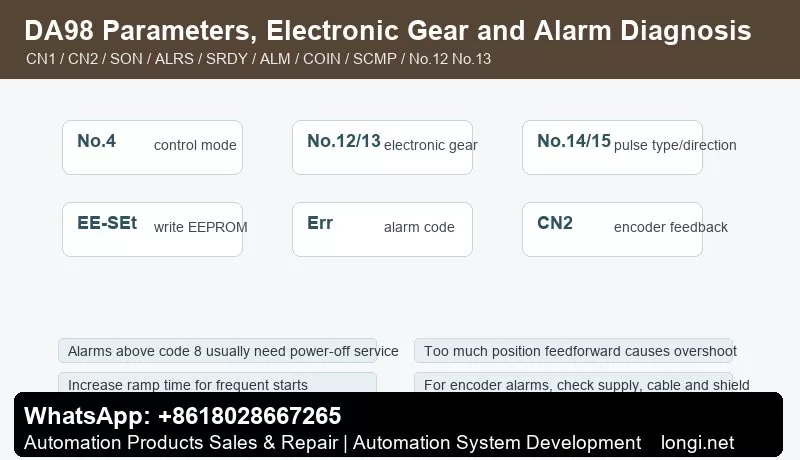
No.12 is the position command pulse division numerator. No.13 is the denominator. Together they define the electronic gear ratio. Because a 2500-line encoder becomes 10000 feedback pulses per revolution after four-times counting, the ratio must account for encoder pulses, screw pitch, reduction ratio and CNC pulses per millimeter.
Proportional size error usually means electronic gear error. Bidirectional repeatability error points more to backlash, coupling, encoder feedback or gain setting.
Speed Mode and Internal Speeds
Set No.4 to speed mode when DA98 is used as a speed servo. Internal speeds are selected through SC1/SC2 and parameters such as No.24-No.27. SCMP speed-arrival output can be used by PLC. JOG speed is set by No.21 and is useful for no-load testing.
If speed mode does not run, check No.4, SON, ALM, SC1/SC2, speed parameters, FSTP/RSTP, torque limit and maximum speed No.23. If no-load operation is normal but load operation alarms, check load inertia, ramp time No.7 and torque limits No.34-No.37.
Gain Tuning
Tune speed loop first, then position loop. Higher speed proportional gain improves stiffness but can cause vibration. Higher position proportional gain reduces following error but can cause overshoot. Position feedforward is normally set to zero unless high response is required; excessive feedforward can destabilize the position loop.
Frequent starts, large inertia and short ramp time can cause overheating or overvoltage. Start with conservative ramp time, then improve response gradually.
EEPROM Parameter Write
Parameter edits are in memory until written. EE-SEt writes memory parameters into EEPROM. Select EE-SEt, press and hold Enter for more than three seconds, wait for StArt and then FInISH. EE-dEF restores defaults, but use it only after confirming drive model No.1.
Before delivery, record No.1, No.4, No.7, No.9, No.10, No.12, No.13, No.14, No.15, No.20, No.21, No.23 and No.34-No.37.
Alarm Diagnosis
Main-circuit overvoltage: usually caused by fast deceleration, high inertia, braking problem or power abnormality. Increase No.7 and check load.
Encoder faults: check CN2 supply, cable, shield, pin order, encoder and interface circuit. Long cable can reduce encoder supply voltage.
Following error: check electronic gear ratio, pulse frequency, position gain and mechanical jam. Do not only enlarge the error window.
Vibration with alarm: check coupling, inertia, speed gain, position gain and encoder cable before replacing the drive.
Reset invalid: alarms above code 8 usually cannot be cleared only by ALRS; power-off inspection is required.
The reliable DA98 workflow is: confirm motor and drive model, wire TB/CN1/CN2, set No.4 mode, calculate No.12/No.13 electronic gear, run no-load JOG, test low-speed pulse motion, tune speed and position loop, execute EE-SEt, then verify under load.