
1. Overview of the Fault Symptom
Yaskawa SERVOPACK servo drives are widely used in industrial automation equipment. Older Yaskawa series such as SGDM, SGDH, and SGDV are commonly found in CNC machines, printing machines, packaging equipment, semiconductor machinery, handling systems, robotics-related mechanisms, dedicated production lines, and high-precision positioning systems. Because these machines often operate for many years in demanding industrial environments, servo systems may develop alarms, failure to enable, unstable operation, unexpected stopping, or complete axis failure.
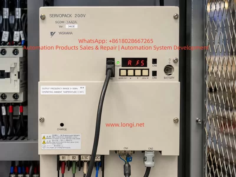
One common fault on the Yaskawa SGDM series is the A.F5 alarm. In many field cases, technicians may see “A.F5” on the display and simply interpret it as “AF5.” Some may immediately assume that the servo drive itself is defective. However, this alarm does not always mean that the SERVOPACK is damaged. In many cases, it points to an abnormal motor power circuit, especially a disconnection or poor contact in the U, V, W motor power lines between the servo drive and the servo motor. It may also be caused by an open motor winding, loose terminal, faulty connector, damaged cable, or an internal output detection or current detection fault inside the servo drive.
From a repair and troubleshooting perspective, the A.F5 alarm should be handled according to the principle of checking the external motor circuit first and the internal drive circuit second. It is not correct to dismantle the drive immediately after seeing A.F5, nor is it correct to only check parameters or control signals. The first priority should be to inspect the motor power cable, motor winding, intermediate terminals, connectors, contactors, drag-chain cables, and the U/V/W output path. Only after the external circuit has been confirmed normal should the internal power output stage and detection circuit of the SERVOPACK be considered.
2. Basic Meaning of the A.F5 Alarm
On the Yaskawa SGDM servo drive, A.F5 generally indicates a Servomotor Disconnection Alarm.
It can be understood as:
Servo motor power line disconnection alarm, servo motor connection abnormality alarm, or output circuit abnormality alarm.
The core meaning is that when the drive attempts to control the servo motor, it detects that the motor power circuit is not forming a normal current path, or that the output-side condition does not match the expected state of a normally connected motor. As a result, the drive determines that the motor may not be connected correctly, the power cable may be open, one output phase may be missing, or the internal detection circuit may be abnormal.
It is important to note that A.F5 is not primarily an encoder alarm and is not a general parameter error. A complete servo system includes several parts:
- Servo drive main power circuit;
- Servo drive control board;
- Servo motor;
- Motor power cable;
- Encoder feedback cable;
- Control signal wiring;
- Servo ON, limit, emergency stop, and safety circuits;
- Mechanical load.
The A.F5 alarm mainly concerns the power output relationship between the servo drive and the servo motor. The key inspection targets are the U, V, and W motor phases and the related output detection circuit.
3. Common Timing of the A.F5 Alarm
Before judging the fault location, it is necessary to confirm when the A.F5 alarm appears. Different alarm timing often indicates different fault directions.
3.1 A.F5 Appears Immediately After Control Power Is Turned On
If the servo drive displays A.F5 immediately after the control power is applied, before the Servo ON signal is given, the fault is more likely related to the internal detection circuit of the drive.
Possible causes include:
- Abnormal internal output detection circuit;
- Abnormal current detection circuit;
- Faulty connection between the power board and control board;
- Aging electronic components inside the drive;
- Abnormal main circuit detection signal;
- Previous output short circuit, explosion, water ingress, moisture damage, or severe overload.
External motor wiring problems cannot be completely ruled out, especially if the motor cable is severely shorted or connected incorrectly. However, if the alarm appears before servo enable, the SERVOPACK itself deserves more attention.
3.2 Power-On Is Normal, but A.F5 Appears After Servo ON
If there is no alarm after power-on, but A.F5 appears when the servo is enabled, when the machine is started, or when the axis is about to run, the external motor power circuit is more suspicious.
This is a very common field situation. Typical causes include:
- One phase of U/V/W motor cable is open;
- Motor power connector is loose;
- Motor terminal box wiring is loose;
- Intermediate terminal block has poor contact;
- Internal conductor of a drag-chain cable is broken;
- Output-side contactor contact is burnt or unreliable;
- Servo motor winding is open;
- Incorrect wiring after repair, relocation, or modification;
- Loose screws on the drive output terminals.
In this case, the correct inspection direction is from the drive output terminals to the motor end, section by section.
3.3 A.F5 Appears Occasionally During Operation
If the equipment can run but occasionally stops with A.F5 after a period of operation, the fault is often intermittent.
Common causes include:
- Drag-chain cable conductor is half-broken due to repeated bending;
- Motor connector loses contact under vibration;
- Terminal block oxidation or looseness;
- Motor cable insulation or conductor damage;
- Motor winding internal break changes with temperature;
- Internal solder joint or connector problem inside the drive;
- Poor thermal stability of the current detection circuit.
Intermittent faults are more difficult to locate than fixed faults. Static measurement may appear normal, but the problem may occur only during movement, vibration, or heating. In such cases, cable bending tests, hot-state testing, operation monitoring, and substitution testing are necessary.
4. Difference Between A.F5 Alarm and Encoder Fault
In field maintenance, some technicians tend to classify all servo alarms as “encoder problems.” This is inaccurate. In a Yaskawa servo system, encoder-related alarms usually involve encoder communication, feedback abnormality, encoder disconnection, encoder data error, or battery alarm. The core of A.F5 is not the feedback signal but the motor power output circuit.
The difference can be summarized as follows:
| Item | A.F5 Alarm | Encoder-Related Alarm |
|---|---|---|
| Main target | Motor power cable U/V/W | Encoder feedback cable |
| Circuit involved | Main power output, current detection, motor winding | Encoder power, communication, feedback signal |
| Typical symptom | Alarm after Servo ON, motor does not run | Feedback abnormality, homing error, encoder communication alarm |
| Main inspection point | U/V/W cable, motor winding, output terminals | Encoder connector, battery, feedback cable, encoder |
| Must the motor be faulty? | No | No |
| Must the drive be faulty? | No | No |
Therefore, when A.F5 occurs, the inspection should not focus only on the encoder cable, nor should the encoder be replaced blindly. The correct focus should be the motor three-phase power cable and the drive output circuit.
5. Main Causes of the A.F5 Alarm
5.1 Servo Motor Power Cable Disconnection
This is the most direct and common cause. The servo motor power cable normally includes U, V, W phases and PE ground. The drive outputs three-phase PWM voltage through U, V, and W to control the servo motor. If any phase is disconnected, the drive cannot establish normal output current and may trigger A.F5.
The disconnection may occur at:
- Drive output terminals;
- Cabinet terminal block;
- Aviation connector;
- Servo motor connector;
- Drag-chain cable;
- Cable bending point;
- Motor terminal box;
- Rewired location after repair, relocation, or modification.
This is especially common in machines with moving axes, robotic arms, gantry systems, and drag-chain applications. The cable may look intact externally, but the copper conductor inside may already be half-broken or completely open.
5.2 Loose Terminal or Poor Contact
Loose terminals are common in industrial equipment. Servo drive U/V/W outputs carry fast-changing current. If the terminal is not tight, heating, oxidation, arcing, increased contact resistance, or intermittent disconnection may occur.
Typical signs include:
- Blackened terminal;
- Discolored cable lug;
- Loose terminal screw;
- Yellowed or deformed insulation sleeve;
- Burnt smell near the terminal;
- Alarm becomes more frequent during vibration.
Machines with strong vibration, such as punching feeders, packaging machines, printing machines, woodworking machines, and CNC machine tools, are more likely to develop loose terminals.
5.3 Open Servo Motor Winding
If the motor winding is internally open, the drive will also fail to detect a normal motor load. After power-off, the three-phase motor winding resistance can be measured to make a preliminary judgment.
Measurements should be taken between:
- U-V;
- V-W;
- W-U.
The three resistance values should be close to each other. If one pair shows infinite resistance, the winding or internal lead wire may be open. If the three values are obviously unbalanced, the motor may also have an internal fault.
For large servo motors, the winding resistance can be very low, and ordinary multimeters may not give highly accurate readings. Therefore, the relative balance of the three readings is usually more important than the absolute value.
5.4 Intermediate Contactor or Terminal Block Fault
Some machines use an intermediate contactor, terminal block, plug connector, or safety disconnect device between the servo drive and the motor. In general, it is not recommended to casually install a contactor on the U/V/W output side of a servo drive, because the servo output is a high-frequency PWM waveform and improper switching may cause impact or detection errors.
If the original machine design does include an output-side contactor, the following points should be checked carefully:
- Whether the contactor contacts are burnt;
- Whether all three phases close reliably and simultaneously;
- Whether the contactor coil is energized properly;
- Whether terminal blocks are loose;
- Whether one phase has high contact resistance;
- Whether a safety circuit is incorrectly interrupting the output side.
A contactor may appear conductive during static measurement, but under load its voltage drop may increase, causing the drive to report A.F5.
5.5 Servo Motor Model Mismatch or Incorrect Wiring
Yaskawa servo drives require correct motor matching. If the motor, drive, or cable has been replaced, there may be motor mismatch, wrong phase sequence, or incorrect connector pin definition.
Common wiring mistakes include:
- Connecting a motor from a different series to an incompatible drive;
- Incorrect U/V/W phase sequence;
- Motor power cable connected to wrong terminals;
- Input power and motor output mistakenly reversed;
- Motor cable connected to braking resistor terminals;
- Incorrect pin assignment when using a non-original cable.
Reversing the input power and motor output is especially dangerous and may directly damage the power module. During repair, L1/L2/L3 input terminals and U/V/W output terminals must be clearly distinguished. Wire color alone should not be used as the only basis.
5.6 Internal Power Module Fault
If the external motor, cable, connector, and terminal block are confirmed normal but A.F5 remains, an internal drive fault must be considered.
The SGDM series is an older Yaskawa servo drive family. Many units have been operating for more than ten or even twenty years. Aging components, damaged power modules, cracked solder joints, and current detection drift are all possible.
Common internal problems include:
- Damaged IGBT module;
- One output phase open internally;
- Aging gate driver optocoupler;
- Abnormal gate drive circuit;
- Current detection circuit fault;
- Hall current sensor or shunt resistor fault;
- Poor connection between power board and control board;
- DC bus voltage detection abnormality;
- Output detection comparator circuit fault.
If the drive previously experienced output short circuit, motor cable short circuit, water ingress, heavy dust contamination, capacitor failure, or power module explosion, the probability of internal damage is higher.
5.7 Control Board or Detection Circuit Fault
The A.F5 alarm depends on the internal detection logic of the drive. If the detection circuit itself is faulty, the drive may falsely report motor disconnection even when the external motor cable is normal.
Examples include:
- Current sampling signal not reaching the control board;
- Damaged operational amplifier;
- Abnormal isolated feedback signal;
- Comparator output error;
- Changed value of analog sampling resistor;
- Damaged control board input channel;
- Poor contact in board-to-board ribbon cable or connector.
This type of fault usually requires professional bench repair, circuit measurement, signal tracing, substitution testing, and oscilloscope analysis.
6. Correct Field Troubleshooting Procedure
Step 1: Record the Alarm Condition
Before troubleshooting, record the following information:
- Servo drive model;
- Servo motor model;
- Alarm code;
- Whether the alarm appears at power-on or after Servo ON;
- Whether the alarm occurs intermittently during operation;
- Whether the motor, cable, or drive was repaired or replaced before;
- Whether the machine was relocated, rewired, flooded, shorted, or overloaded;
- Whether abnormal noise, smell, breaker trip, or mechanical jamming occurred before the alarm.
These details help narrow down the fault quickly.
Step 2: Power Off and Confirm DC Bus Discharge
There is a high-voltage DC bus inside the servo drive. Even after power is turned off, the capacitors may retain dangerous voltage. Before checking U/V/W terminals or opening the drive, the main power must be disconnected and the DC bus voltage must be confirmed safe.
Safety requirements include:
- Turn off the machine main power;
- Wait until the CHARGE indicator goes out;
- Use a multimeter to confirm that the DC bus voltage has dropped to a safe level;
- Do not touch main circuit terminals directly;
- Do not plug or unplug motor or encoder cables while powered;
- Do not disconnect U/V/W wiring while the drive is enabled.
The servo output side carries high-frequency PWM voltage. Live operation can cause electric shock, short circuit, or secondary damage.
Step 3: Inspect the U/V/W Output Terminals
Check the motor output terminals at the bottom of the drive:
- U;
- V;
- W;
- PE ground.
Inspection items include:
- Whether terminal screws are loose;
- Whether cable lugs are tightly pressed;
- Whether terminals are burnt or blackened;
- Whether cables are detached;
- Whether wiring is incorrect;
- Whether wire numbers match the drawing;
- Whether copper strands are exposed and causing short circuit;
- Whether oil, dust, or metal chips are present.
If loose terminals are found, re-crimp the cable lug, clean oxidation, and tighten the terminal. If cable lugs or terminal blocks are already burnt, they should be replaced rather than simply tightened.
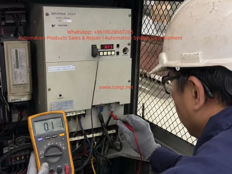
Step 4: Measure Motor Winding Resistance
Disconnect the U/V/W motor cable from the drive and measure the motor-side three-phase winding resistance.
| Measurement | Judgment |
|---|---|
| U-V | Should show low resistance |
| V-W | Should show low resistance |
| W-U | Should show low resistance |
| Comparison of three values | Should be basically balanced |
| One pair reads infinite | Possible winding open circuit or cable break |
| One pair obviously higher | Possible poor contact or winding abnormality |
If the measurement is taken at the drive end, the result includes both the cable and motor. If abnormal, continue measuring at the motor connector or motor terminal box to distinguish cable fault from motor fault.
Step 5: Measure Insulation to Ground
Although A.F5 mainly indicates a disconnection alarm, insulation should also be checked. Damaged cable insulation or motor winding leakage may cause other alarms or indirectly affect the drive detection.
Use a megohmmeter to measure:
- U to PE;
- V to PE;
- W to PE;
- Motor winding to motor housing.
For a servo motor and cable, insulation should be high. If insulation is low, the motor, cable, or connector may be damp, damaged, contaminated, or aged.
Important: the servo drive must be disconnected before using a megohmmeter. Never apply megger voltage directly to the drive electronics, as this may damage the drive.
Step 6: Inspect Motor Connector and Intermediate Connectors
Servo systems often use aviation plugs or special connectors. Connector faults are common, especially in environments with oil mist, coolant, dust, and vibration.
Check for:
- Bent pins;
- Pins pushed backward;
- Connector not locked;
- Oil or water inside the connector;
- Oxidized or blackened pins;
- Poor shield termination;
- Cable strain at connector tail;
- Loose crimping inside the plug.
If oil or water has entered the connector, simply blowing it dry may not be reliable. The connector should be cleaned, dried, re-crimped, or replaced if necessary.
Step 7: Inspect Drag-Chain Cable
For moving axes, the drag-chain cable is a key suspect. Drag-chain cable damage can be hidden, and static measurement may not reveal it.
Practical checking methods include:
- Measure continuity while bending the cable;
- Move the machine to different positions and measure again;
- Check whether the alarm only occurs at a certain axis position;
- Temporarily bypass the drag-chain cable with another motor cable;
- Check whether the bending radius is too small;
- Inspect for clamping, pulling, or mechanical damage.
If A.F5 disappears after bypassing the original cable, the original cable or intermediate connector is very likely faulty.
Step 8: Use Substitution Testing to Identify Motor or Drive Fault
If there is another same-model axis or spare equipment on site, substitution testing can be used, but it must be done carefully.
Possible methods include:
- Connect a known-good motor to the suspected drive;
- Connect the suspected motor to a known-good drive;
- Swap motor power cables;
- Swap encoder cables;
- Swap drives.
Before substitution, confirm that voltage, power rating, motor model, encoder type, and parameters are compatible. Randomly connecting different motor and drive models may cause damage.
Typical conclusions are:
- If the fault follows the motor, the motor or motor cable is faulty;
- If the fault follows the drive, the drive is faulty;
- If the fault follows the cable, the cable or connector is faulty;
- If the fault disappears after reconnection, there may have been poor contact.
7. Internal Repair Logic of the Servo Drive
When the external motor cable, motor winding, connector, and terminal block are all confirmed normal but A.F5 remains, the drive should be inspected internally.
7.1 Check the Power Module
The SGDM servo drive uses an internal power module or IGBT output structure. During repair, check:
- Whether the P-N DC bus is shorted;
- Whether U/V/W to P or N show abnormal short circuit;
- Whether the IGBT bridge diode characteristics are normal;
- Whether one output phase is open;
- Whether the module has cracks, burns, or explosion marks;
- Whether the module base shows overheating discoloration.
If the IGBT module is damaged, replacing a fuse or simply resetting the alarm is not enough. The gate drive circuit, motor cable, and load must also be checked, otherwise the new module may fail again.
7.2 Check the Gate Drive Circuit
The IGBT gate drive circuit controls the switching of the power module. If the drive signal is abnormal, output current cannot be established correctly, and the system may judge the motor as disconnected or output abnormal.
Inspection points include:
- Whether gate drive power supply is normal;
- Whether upper and lower bridge gate signals are normal;
- Whether driver optocouplers are damaged;
- Whether gate resistors are open or changed in value;
- Whether protection diodes are shorted;
- Whether the driver board is burnt;
- Whether board-to-board connectors are reliable.
This area usually requires an oscilloscope and isolated measurement conditions. It is not recommended for untrained field personnel to test blindly.
7.3 Check the Current Detection Circuit
The servo drive often depends on output current feedback to judge motor connection status. If the current detection circuit fails, the control board may interpret the output as abnormal even if the power module is working.
Common detection components include:
- Current transformer;
- Hall current sensor;
- Shunt resistor;
- Operational amplifier;
- Comparator;
- A/D input channel;
- Isolation amplifier;
- Signal filter circuit.
If one phase current feedback is missing, the drive may falsely report motor disconnection or output phase loss.
7.4 Check the Connection Between Control Board and Power Board
A common issue in older drives is oxidized board connectors, poor ribbon-cable contact, or cracked solder joints. This is especially common in high-temperature, dusty, oily, or vibrating environments.
Check:
- Oxidized connectors;
- Loose ribbon cables;
- Cracked solder joints;
- Warped circuit boards;
- Blackened pins;
- Electrolytic capacitor leakage corrosion;
- Conductive dust contamination.
For old drives, cleaning the boards, reseating connectors, and re-soldering suspicious joints may solve intermittent alarms.
8. Common Misjudgments During Repair
8.1 Looking Only at the Alarm Code and Ignoring Alarm Timing
The same A.F5 alarm can have different causes depending on whether it appears at power-on, after Servo ON, or during operation. Ignoring timing can lead to the wrong troubleshooting direction.
8.2 Checking Only the Encoder Cable Instead of the Motor Power Cable
The key circuit of A.F5 is not the encoder cable but the motor power circuit. The encoder cable can be inspected, but it should not be treated as the main target.
8.3 Assuming the Cable Is Good Because a Multimeter Shows Continuity
A half-broken drag-chain cable may appear conductive during static measurement but open during movement. For intermittent alarms, dynamic bending tests or temporary cable replacement are necessary.
8.4 Using a Megohmmeter Without Disconnecting the Drive
Megger voltage can damage drive electronics. When measuring motor or cable insulation, the drive side must be disconnected first.
8.5 Replacing the Drive Blindly
If the root cause is a motor cable break, short circuit, or motor winding fault, replacing the drive may not solve the problem and may even damage the replacement drive.
8.6 Ignoring Mechanical Jamming
Although A.F5 mainly indicates a motor connection abnormality, severe mechanical jamming may cause abnormal servo current and mislead troubleshooting. The mechanical axis, brake release, and load condition should also be checked.
9. Recommended Standard Troubleshooting Flow
For a Yaskawa SGDM servo drive with A.F5 alarm, the following sequence is recommended:
- Confirm that the displayed alarm is A.F5;
- Record when the alarm appears;
- Power off and confirm DC bus discharge;
- Check the drive U/V/W output terminals;
- Check the motor power wiring;
- Measure the three-phase motor winding resistance;
- Measure motor and cable insulation to ground;
- Inspect motor connector, terminal block, and intermediate contactor;
- Check whether drag-chain cable conductors are broken;
- Temporarily bypass intermediate wiring for testing;
- Use substitution testing to distinguish motor, cable, and drive;
- After confirming the external circuit is normal, inspect the drive internally;
- Check IGBT, gate drive circuit, current detection circuit, power board, and control board;
- Perform no-load testing after repair;
- Connect the motor and run at low speed;
- Finally restore machine load and test normal operation.
The principle is:
External before internal; simple before complex; low-risk checks before dismantling; root cause confirmation before replacing parts.
10. Key Tests After Repair
After repairing an A.F5 fault, it is not enough to confirm that the alarm disappears. A complete test should be performed.
10.1 Static Test
Check:
- Drive powers on without alarm;
- Control power is normal;
- Main power is normal;
- DC bus voltage is normal;
- Cooling fan operates normally;
- No abnormal sound or smell.
10.2 Servo Enable Test
After applying Servo ON, observe:
- Whether A.F5 reappears;
- Whether the motor becomes energized;
- Whether the brake releases properly;
- Whether the motor vibrates;
- Whether current is abnormal;
- Whether overcurrent, overload, or encoder alarms appear.
10.3 Low-Speed Run Test
Run the motor forward and reverse at low speed and observe:
- Whether the rotation direction is correct;
- Whether operation is smooth;
- Whether there is abnormal noise;
- Whether current is balanced;
- Whether speed feedback is stable;
- Whether stopping is normal.
10.4 Load Test
After restoring the machine load, test:
- Acceleration and deceleration;
- Positioning accuracy;
- Long-term operation;
- Whether drag-chain movement affects the alarm;
- Motor and drive temperature rise;
- Whether terminals become hot.
Only after the machine runs continuously without the alarm should the repair be considered complete.
11. Preventive Maintenance Recommendations
For older Yaskawa SGDM servo systems, regular maintenance can reduce the occurrence of A.F5 and similar alarms.
11.1 Tighten Terminals Regularly
Input terminals, output terminals, motor terminal boxes, and cabinet terminal blocks should be checked regularly. In high-power servo systems, loose terminals can cause heating, burning, and poor contact.
11.2 Inspect Drag-Chain Cables Regularly
Drag-chain cables are consumable parts. Bending points, fixing points, and moving sections should be inspected frequently. Cables beyond their service life should be replaced in advance.
11.3 Keep the Electrical Cabinet Clean
Dust, oil mist, and metal particles can contaminate circuit boards and terminals. Electrical cabinets should be kept clean, dry, and well ventilated.
11.4 Prevent Oil and Water from Entering the Motor
Servo motor connectors, motor terminal boxes, and cable entry points should be protected from coolant, oil, and moisture. This is especially important for machine tools, cleaning equipment, and food packaging machines.
11.5 Avoid Random Switching on the Output Side
Do not casually install contactors, switches, or plug-in structures on the U/V/W output side of the servo drive. If output switching is required by machine design, it must follow proper servo system rules and only switch when the drive is stopped and has no output.
11.6 Mark Wires Clearly After Maintenance
Many servo faults occur after incorrect reconnection. Before disconnecting wires, take photos, mark wire numbers, and record terminal positions. During reassembly, do not rely only on wire color. Always verify according to the drawing and terminal definition.
12. Conclusion
The A.F5 alarm on a Yaskawa SGDM servo drive is essentially a servomotor disconnection or output circuit abnormality alarm. It should not be simply interpreted as “the drive is bad,” nor should the troubleshooting focus only on the encoder or parameters. The correct analysis should focus on the motor power circuit, especially the U/V/W output cable, motor winding, terminal block, connector, drag-chain cable, intermediate contactor, and the internal output detection and power drive circuits of the SERVOPACK.
In practical repair work, if A.F5 appears after Servo ON, the external motor cable, motor winding, connector, and terminal contact should be suspected first. If A.F5 appears immediately after control power is applied, or if the external circuit is fully confirmed normal but the alarm remains, the internal power module, current detection circuit, gate drive circuit, and control board should be inspected.
For old SGDM servo drives, long service life often leads to aging electronic components, poor board contact, and deterioration of the power section. Therefore, successful troubleshooting requires both field electrical diagnosis and electronic repair capability. A systematic process should be followed: alarm timing analysis, external circuit inspection, motor winding measurement, dynamic cable testing, substitution verification, and internal drive inspection.
Although A.F5 appears to be a simple alarm code, it involves the servo system’s power output, motor connection, current detection, and protection logic. For maintenance personnel, the key is not only to remember the alarm code, but to understand the detection logic and fault chain behind it. Only then can the root cause be located quickly, repair efficiency improved, unnecessary part replacement avoided, and machine downtime reduced.