1. Background of the Fault
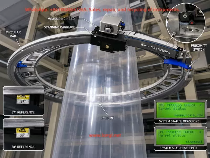
Online film thickness gauges are widely used in blown film, cast film, composite film, packaging film, and other plastic film production lines. Their main function is to continuously monitor the thickness of the film during production and provide real-time data to operators or to an automatic control system. In many film extrusion lines, the measuring head is mounted on a circular scanning carriage. During normal operation, the carriage moves around the film bubble or across the measuring path, allowing the gauge to build a complete thickness profile.
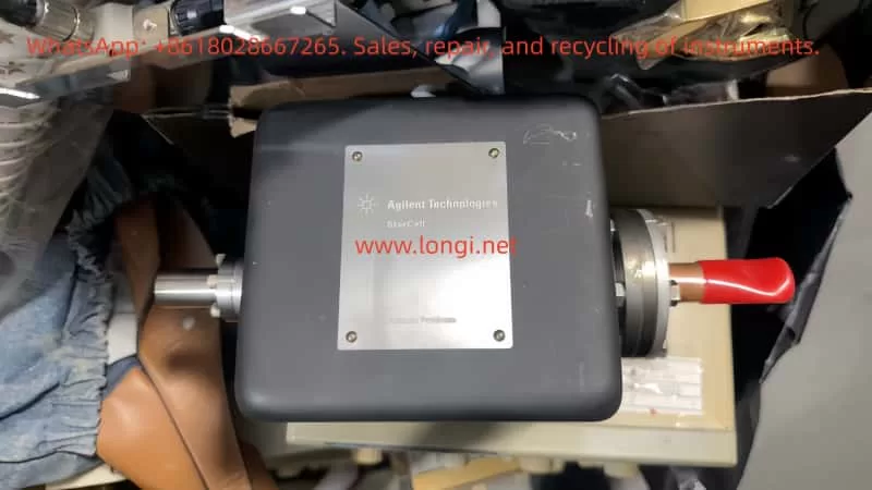
A KNC-400 type film thickness measuring system is not just a single sensor. It is a complete measuring and motion-control system. It usually includes the measuring head, circular scanning carriage, drive motor, guide rail or belt mechanism, pneumatic air-bearing or air-gap control, proximity switch or reference-position sensor, data processor, industrial I/O module, communication interface, and upper-level display software.
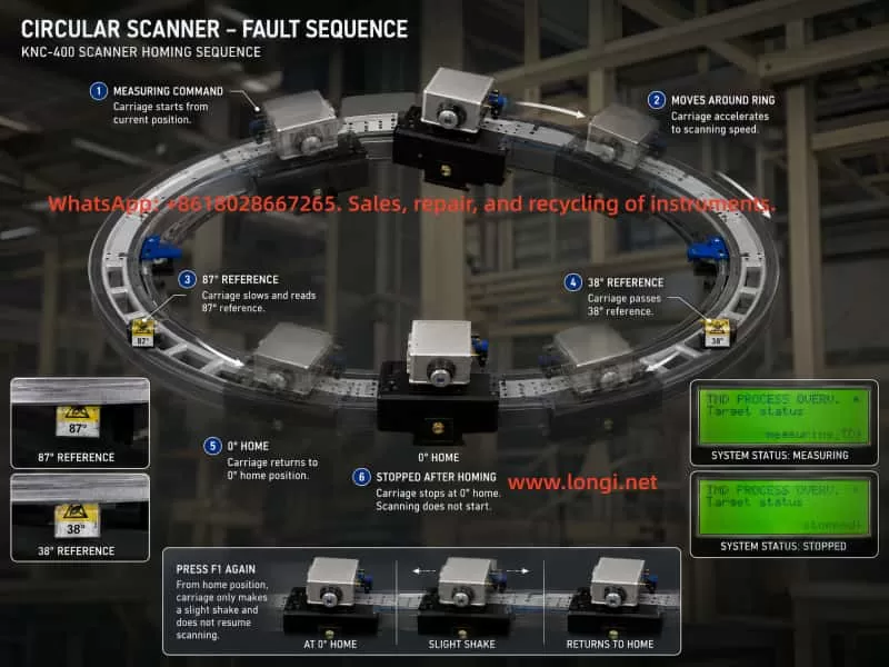
In this case, the customer reported the following symptoms. After power-on, the small local display showed “Warm Up / waiting” for more than twenty minutes without any obvious change. When F1 was pressed to start measurement, the measuring carriage only shook slightly and did not start continuous scanning. However, after the carriage was manually pushed away from the zero position, pressing F1 caused the carriage to move. It passed two mechanical reference blocks and then returned to the zero position, where it stopped. After pressing F1 again to stop and restart, the same symptom returned: the carriage only moved slightly and stopped.
The upper computer displayed the Kdesign software interface, including pages such as Trend, Polar diagram, Linear diagram, Alarm list, and production data. The alarm history included messages such as “No communication to the kundig measuring device – Check Power Supply and data link” and repeated “Valve error compare special ALARM-page appeared/disappeared” records.
Several field observations are especially important. The measuring head had continuous compressed air blowing. The pressure display fluctuated around 290–300 mBar. When the pressure was manually increased, it later returned to the original range, which suggests that the system may have automatic pressure regulation. The ME and SE values changed synchronously when the pressure was adjusted. The small display on the measuring head showed changes before and after pressing F1. The measuring head status lamp remained green. The control cabinet contained Phoenix Contact I/O modules, power supply modules, a data processor board, and an RS-485 communication board, all with indicator lights. However, when the carriage passed the two reference blocks, the customer did not observe any obvious change in the Phoenix Contact input module indicators or the LEDs on the small control board.
At first glance, this fault can easily be mistaken for a motor stall, mechanical jam, or drive failure. However, the later tests show that the carriage can move when pushed away from the zero position and can return to zero under F1 command. Therefore, the failure cannot simply be attributed to a bad motor or a completely jammed mechanical system. The more likely fault area is the transition between “homing completed” and “continuous measuring scan allowed.”
This case is technically valuable because it shows a common problem in online measuring equipment repair: the apparent symptom is “the machine does not move,” but the root cause may be in position feedback, pressure control, communication, measurement permission logic, or software status, rather than in the motor itself.
2. Basic Operating Logic of a KNC-400 Online Thickness Gauge
To diagnose this kind of fault correctly, it is necessary to understand the normal operating sequence of a circular scanning film thickness gauge.
After power-on, the data processor and the measuring head usually enter an initialization stage. During this stage, the system checks the power supply, internal communication, measuring head status, temperature condition, pneumatic pressure condition, position sensor condition, and external interlocks. If the measuring head or measuring environment requires stabilization, the local display may show messages such as “Warm Up,” “waiting,” or similar status indications.
When the operator presses F1 to start measurement, the system does not necessarily begin continuous scanning immediately. In many circular scanning systems, the carriage first performs a homing or reference-position search. The controller must know where the carriage is before it can start a complete measuring cycle. This reference position is normally detected by a proximity switch, optical sensor, Hall sensor, or another position feedback device.
Only after the controller confirms the correct reference position, and after all measuring conditions are satisfied, does the carriage enter continuous scanning mode. During continuous scanning, the measuring head collects film thickness data and sends it to the data processor and upper computer. The software then displays actual profiles, basic centering profiles, linear diagrams, trend diagrams, maximum and minimum thickness values, average thickness, and other measurement data.
In this case, the customer confirmed an important point: in the past, the KNC-400 could start and run even when no film was being produced. It simply had no valid thickness data. This means the current problem is not caused merely by the absence of film. The system should be able to perform an empty scan. Therefore, the current failure is more likely caused by a missing internal permission signal, abnormal position feedback, pressure control problem, communication issue, or measurement state error.
The fact that the carriage can move after being manually pushed away from zero means that F1 is accepted by the system and the motion control loop still has basic functionality. The motor, transmission, belt, and guide rail cannot be considered completely failed. The key issue is that after the carriage returns to the zero position, the system does not continue into normal scanning.
3. Analysis of the Main Fault Phenomena
3.1 The “Warm Up / waiting” Message Does Not Disappear
The “Warm Up / waiting” indication does not automatically mean a hardware fault. Many online measuring systems require a warm-up period before measurement is allowed. The system may wait for the measuring head temperature, internal electronics, pneumatic air gap, or communication state to stabilize.
However, if the system remains in this state for more than twenty minutes without any progress, it usually means that one of the measuring permission conditions has not been met. Possible causes include:
The actual measuring head temperature has not reached the target value.
The air pressure has not reached the required range.
The measuring head communication is abnormal.
The data processor has not received a valid measuring head status.
An external interlock signal is missing.
The carriage position or zero reference is not confirmed.
The measuring head remains in a stopped, waiting, or initialization state.
The system parameter or internal status is abnormal.
In this case, the local display showed a target temperature of 32.0°C. At first, only the target temperature was available, while actual temperature values such as ME, SE, Actual, or Current were not clearly identified. Later, the customer reported that ME and SE changed when the air pressure was adjusted. This proves that the measuring head is not completely dead; at least part of its sensing and display functions are active.
Therefore, “Warm Up / waiting” should be treated as a general waiting status, not as a single fault code. It may be caused by temperature, pressure, communication, position feedback, or external interlock conditions.
3.2 Pressing F1 Causes Only a Slight Shake
When F1 is pressed and the carriage only shakes slightly, it is tempting to suspect a blocked motor, jammed carriage, damaged belt, or failed drive output. But the later field test does not support this conclusion.
After the carriage was manually pushed away from the zero position, pressing F1 caused it to move and return to the zero point. This proves that the motor and transmission can produce effective motion. If the motor were completely stalled, or if the mechanism were seriously jammed, the carriage would not be able to perform this movement.
A more reasonable explanation is that when the carriage is already near the reference position, the controller only makes a short positioning or confirmation movement. Because the next permission condition is not satisfied, the controller does not start continuous scanning. As a result, the customer sees only a small shake.
This kind of symptom is common in automated equipment. The machine appears not to run, but in reality it is waiting for the next logical condition. The difference between “cannot move” and “not allowed to continue moving” is very important in fault diagnosis.
3.3 The Carriage Can Return to Zero After Being Manually Moved
This is the most important observation in the whole case.
It proves that the F1 command is recognized.
It proves that the motion system has at least partial functionality.
It proves that the motor and transmission are not completely defective.
It proves that the system can perform a homing-related action.
It suggests that the failure occurs after the homing action is completed.
In many industrial systems, the machine can return to home but cannot enter automatic operation. This usually means the problem is not the basic motion hardware, but the automatic-cycle enable condition. Examples include missing reference confirmation, missing safety input, missing process-ready signal, abnormal pressure, communication timeout, or incorrect process state.
For the KNC-400 in this case, the most likely point of failure is the logic between “home position found” and “continuous measuring scan started.”
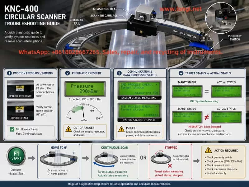
3.4 Pressure Fluctuation Around 290–300 mBar
The pressure display fluctuates around 290–300 mBar. When F1 is pressed, the pressure changes. The customer also reported that manual pressure adjustment affects ME and SE values, but the pressure later returns toward the original value. This suggests that the pneumatic system may be closed-loop controlled, rather than purely manually regulated.
In an air-bearing or air-gap measuring head, stable pressure is critical. If the pressure is too low, the measuring head cannot maintain a stable air cushion or measuring distance. If the pressure is too high, it may disturb the film or shift the measuring geometry. If the controller compares target pressure and actual pressure, a deviation may trigger a valve or pressure comparison alarm.
The alarm history contains repeated “Valve error compare” messages. This may indicate that the valve control system, pressure feedback, or pressure comparison logic has detected an inconsistency.
However, the presence of 290–300 mBar pressure means the pneumatic system is not completely inactive. The ME and SE values respond to pressure changes, which indicates that the measuring head and air system have dynamic response. Therefore, the pneumatic system may be abnormal, but it should not be assumed to be the only fault without further confirmation.
The key question is not simply “is there pressure?” but rather:
What is the target pressure?
What is the actual pressure?
What is the allowable tolerance?
Does the actual pressure reach the target pressure during F1 startup?
Is the “Valve error compare” alarm active at the moment of failure, or only historical?
Does the pressure deviation prevent the system from entering measuring mode?
If the target pressure is 300 mBar and the actual pressure is stable around 290–300 mBar, pressure may not be the main cause. If the target pressure is higher and the actual value cannot reach it, then the pressure control loop must be investigated.
3.5 The Proximity Switch and Reference Block Signals Are Unclear
The field inspection originally suggested that there were three mechanical reference blocks on the circular rail. Later, the customer confirmed that there were only two blocks and only one proximity switch, which was partly hidden inside the carriage.
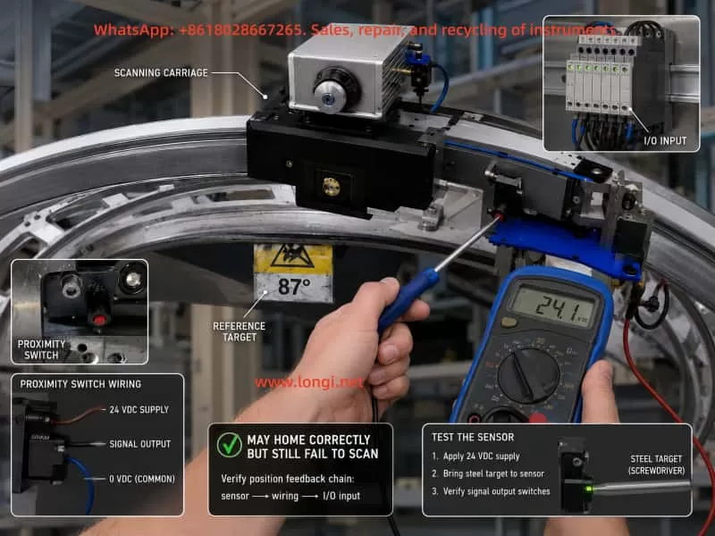
The customer tried touching the proximity switch with a copper sheet but did not observe an indicator light flashing on the measuring head. This test is not reliable. Many industrial proximity switches are inductive sensors, and they respond best to ferrous metal such as steel or iron. Copper and aluminum greatly reduce the sensing distance. A copper sheet may not trigger the switch even if the switch is good.
The correct test is to use a steel screwdriver, steel screw, or iron plate near the sensing face, while measuring the output voltage with a multimeter. The LED on the sensor may be hidden, dirty, damaged, or not visible from the current viewing angle. Therefore, the electrical output must be measured.
The customer also reported that when the carriage passed the two reference blocks, the Phoenix Contact input module indicators did not appear to change. This may be important, but it must be interpreted carefully. The visible indicator may not correspond to the proximity switch input. It may belong to another input, output, status, or communication signal. The correct terminal must be identified by tracing the sensor cable.
If the reference switch signal is abnormal, the system may behave in several ways:
The carriage may return to zero but the controller may not confirm homing completion.
The controller may believe the carriage is always at zero.
The controller may believe a limit condition is permanently active.
The controller may complete homing but fail to switch into scan mode.
The controller may produce only a short movement when F1 is pressed.
The system may remain in waiting or stopped state.
For this reason, the reference-position sensor and its wiring must be treated as a top-priority inspection item.
4. Why This Is Unlikely to Be a Simple Motor Stall or Mechanical Jam
The customer asked whether the fault could be caused by motor stall or mechanical jamming. Based on the available evidence, this is not the most likely diagnosis.
A true motor stall usually has typical features: high motor current, abnormal motor heating, drive alarm, inability to move regardless of position, obvious mechanical resistance, belt slipping, gear jumping, or repeated failed movement attempts. A severely jammed carriage would also be difficult to move manually and would not be able to return to zero over a longer distance.
In this case, after the carriage was pushed away from zero, it moved under F1 command and returned to zero. This means the motor, drive, belt, guide rail, and carriage are capable of movement. The fault is more consistent with a control sequence problem than a basic motion hardware failure.
This does not mean the mechanical system should be ignored. The circular guide rail, rollers, belt tension, reference blocks, carriage bearings, and cable chain should still be inspected. Dirt, wear, local friction, misaligned blocks, or loose mechanical parts can cause unstable movement. But based on the available symptoms, mechanical blockage is not the first suspect.
The key difference is this: the carriage does not fail to move because it lacks mechanical capability; it stops because the control logic does not allow it to enter continuous scanning.
5. Correct Method for Testing the Proximity Switch
The proximity switch is one of the most important parts to verify. In a circular scanning thickness gauge, the controller must know the reference position. If the reference signal is wrong, the entire measuring cycle can be blocked.
A common three-wire proximity switch uses the following wiring convention:
Brown wire: +24 VDC
Blue wire: 0 VDC
Black wire: signal output
This is a common industrial convention, but the actual wiring should still be confirmed from the sensor label or wiring diagram.
The correct test procedure is as follows.
First, measure the supply voltage between brown and blue. It should normally be approximately 24 VDC. If there is no 24 VDC, the sensor has no power. The fault may be in the power supply, terminal block, fuse, cable, connector, or common line.
Second, measure the output voltage between black and blue. Move a steel object toward and away from the sensing face. The voltage should change clearly. For a PNP sensor, the output may change from 0 V to 24 V when activated. For an NPN sensor, the output may change from 24 V to 0 V when activated. The exact direction is less important than the fact that it must change reliably.
Third, trace the signal to the input module. A sensor output change at the sensor itself does not prove that the controller receives the signal. The same signal must be checked at the terminal block, connector, cable chain, Phoenix Contact input module, and data processor input.
Fourth, check whether the signal is stable. A proximity switch can be partially faulty. It may switch only at a very short distance, flicker because of contamination, or fail when the carriage moves. Long-term vibration, metal dust, cable fatigue, and connector oxidation can all cause intermittent switching.
Fifth, test the sensor with the actual mechanical reference block. A handheld steel tool is useful for initial testing, but the final test must verify that the real reference block triggers the sensor at the correct position and distance.
Using copper for this test is not recommended. Copper may not trigger an inductive proximity sensor reliably, so a “no response” result with copper does not prove the sensor is defective.
6. Pressure Control and Valve Error Diagnosis
The repeated alarm history related to “Valve error compare” suggests that the pressure control loop must be checked. In an air-gap measuring system, the controller may compare the target air pressure with the measured actual pressure. If the difference exceeds a threshold, it may block measurement or generate an alarm.
The field pressure reading of approximately 290–300 mBar may be normal, but this cannot be confirmed unless the target pressure is known. The display showed “Pressure 300 mBar” in one screen, which may be either a target or actual value depending on the menu. The temperature target was 32.0°C. The pressure target and pressure actual must be distinguished clearly.
The following checks are recommended.
Record the pressure before pressing F1.
Record the pressure during F1 startup.
Record the pressure after the carriage returns to zero.
Find the pressure target or pressure setpoint in the local menu.
Check whether the actual pressure reaches the target.
Check whether the valve error appears as an active alarm during the failure.
Check the air filter, regulator, tubing, solenoid valve, proportional valve, and measuring head nozzle.
Check whether the pressure sensor output is stable.
The fact that manual adjustment is followed by automatic return may indicate a closed-loop pressure controller. Therefore, the operator should not randomly change the pressure setting. Incorrect pressure may affect measurement calibration and cause additional error.
If the valve error is active during F1 startup, the pneumatic control loop may be preventing continuous scanning. If the valve error is only historical and does not reappear after clearing alarms, it may not be the immediate cause.
7. Meaning of Target Status and Actual Status
The local data processor menu showed status information such as Target status and Actual status. This distinction is important.
Target status refers to the state requested by the operator or upper-level system. For example, after pressing F1, the target status may become “measuring.” This only means that the system has been commanded to measure.
Actual status refers to the real state reported by the measuring system. If the actual status remains “waiting” or returns to “stopped,” the equipment did not truly enter measuring mode, even if the target status says “measuring.”
In this case, the customer observed that after pressing F1, Target status changed to measuring. After pressing F1 again to stop, Actual status changed to stopped. This means the command path is not completely broken. The data processor receives the operator command and changes the requested state. But the system may not be able to maintain actual measuring operation.
This difference is critical. Repeatedly pressing F1 will not solve the problem if the actual measuring permission is missing. The correct direction is to identify why the actual status does not remain in measuring after homing.
Possible reasons include:
Reference position not confirmed.
Pressure condition not satisfied.
Measuring head not ready.
Temperature condition not satisfied.
Communication abnormal.
External interlock missing.
Data processor parameter or status abnormal.
Input module signal missing.
Scan enable logic not satisfied.
8. Communication Alarm Analysis
The alarm history included “No communication to the kundig measuring device – Check Power Supply and data link.” This message should not be ignored. It indicates that, at least at some point, the data processor or upper computer lost communication with the measuring device.
Possible causes include unstable power supply, loose RS-485 wiring, poor connector contact, broken cable in the cable chain, communication board fault, measuring head power fault, shielding problem, or intermittent data link failure.
However, the later field evidence shows that the measuring head display works, the local processor menu is accessible, and the status values change. Therefore, the communication problem may be intermittent or historical rather than a complete current failure.
Still, the communication path should be checked carefully, especially because the measuring carriage moves. Cable-chain wiring is a common failure point in moving measuring systems. A cable may appear normal when stationary, but lose contact when the carriage reaches a certain position. This can cause intermittent communication alarms, sensor signal loss, or missing measurement data.
Recommended checks include:
Inspect all RS-485 terminal screws.
Check the shielding and grounding.
Check the cable chain for bending damage.
Move the carriage slowly while observing communication indicators.
Gently shake the cable at different carriage positions.
Clear historical alarms and check whether communication alarms reappear during F1 startup.
Measure data processor power supply stability.
Check the RS-485 board and connectors for oxidation or contamination.
If a communication alarm reappears exactly when the carriage moves or reaches a certain position, the cable chain or connector should be strongly suspected.
9. Most Probable Fault Chain in This Case
Based on all the available information, the most probable fault chain is as follows.
The KNC-400 powers on and enters a waiting state. When F1 is pressed, the upper computer or local processor issues a measuring command. If the carriage is away from zero, the system first performs a homing movement. The carriage moves past the reference blocks and returns to the zero position. After reaching zero, the system should transition into continuous scanning. However, one or more measuring permission conditions are not satisfied, so the scan does not start. When F1 is pressed again while the carriage is already near zero, the system only performs a short confirmation movement, which appears as a slight shake.
The most likely causes are:
Abnormal zero/reference proximity switch signal.
Incorrect or unstable signal transmission from the proximity switch to the input module.
The controller incorrectly believes the carriage is already at a limit or zero position.
The pressure control comparison condition is not satisfied.
The measuring head remains in waiting status.
The data processor does not receive a valid ready signal from the measuring head.
The external measuring enable or line-run interlock is missing.
The cable chain has an intermittent connection fault.
Historical or active valve/communication alarms are blocking the measuring cycle.
Among these, the proximity switch and its input signal should be checked first, because the movement behavior is strongly related to the zero/reference position.
10. Recommended On-Site Troubleshooting Sequence
A systematic troubleshooting sequence is necessary. Randomly replacing the motor, sensor, data processor, or measuring head may waste time and cost.
Step 1: Clear alarms and reproduce the fault
Record all current alarms first. Then clear the alarm list if the system allows it. Press F1 and reproduce the fault. The new alarms that appear during the fault are more important than old historical alarms.
Step 2: Record Target Status and Actual Status
Before pressing F1, record Target status and Actual status.
After pressing F1, record them again.
After the carriage returns to zero, record them again.
After pressing F1 to stop, record them again.
If Target status becomes measuring but Actual status does not remain measuring, the system command is received but the machine is not allowed to enter measuring mode.
Step 3: Confirm pressure target and actual pressure
Find the pressure-related menu in the local processor or upper software. Record the pressure target, actual pressure, and any pressure or valve alarms. Do not rely only on the 290–300 mBar display unless it is clear whether it is a target or actual value.
Step 4: Test the proximity switch electrically
Use a steel object, not copper. Measure the sensor power supply and output with a multimeter. Confirm that the output changes reliably when the reference block passes.
Step 5: Trace the proximity switch signal to the input module
Find the exact input channel receiving the proximity switch signal. Confirm that the signal changes at the Phoenix Contact module or data processor input. Do not judge from unrelated LEDs.
Step 6: Check the cable chain and moving cables
Move the carriage by hand or during homing while watching the signal and communication indicators. Intermittent cable faults are common in moving measuring devices.
Step 7: Check the pneumatic control loop
Inspect the air filter, regulator, proportional valve, tubing, fittings, and measuring head air outlet. Confirm that the actual pressure reaches the required target and does not oscillate beyond the allowed range.
Step 8: Check communication and power supply
Measure the DC power supply stability. Inspect RS-485 wiring and connectors. Check whether the communication alarm reappears during movement.
Step 9: Check external interlock signals
If the machine previously could run without film but now cannot, there may still be a missing external enable signal, changed parameter, disabled control mode, or lost line-run signal. Check the production line interface and input module signals.
Step 10: Consider board-level faults only after signal checks
Only after the sensor, pressure, communication, and interlock signals are confirmed should the data processor board, RS-485 board, input module, or measuring head electronics be suspected.
11. Practical Diagnostic Principles
Several principles are important in this type of repair.
Do not assume the motor is bad just because the carriage does not scan. If the carriage can return to zero, the motion hardware is at least partly functional.
Do not assume the pneumatic system is normal just because air is blowing. The target pressure and actual pressure must be compared.
Do not test an inductive proximity switch with copper and draw a conclusion. Use steel or iron and verify the output voltage.
Do not rely only on indicator lights. Measure the actual signal with a multimeter.
Do not confuse Target status with Actual status. A command to measure is not the same as actual measuring operation.
Do not ignore historical alarms, but do not let old alarms mislead the diagnosis. The most important alarm is the one that appears during the current fault.
Do not randomly adjust pressure, temperature, or calibration parameters. These settings may affect measurement accuracy.
Always suspect cable-chain wiring in moving systems. A cable can be normal when stationary and fail only during movement.
12. Conclusion
The KNC-400 fault in this case is unlikely to be a simple motor failure or a severe mechanical jam. The carriage can move after being manually pushed away from zero and can return to the zero position under F1 command. This proves that the basic movement system still works.
The real problem is that after the carriage returns to zero, the system does not enter continuous scanning. This points to a missing measurement permission condition, abnormal reference position feedback, pressure control comparison fault, communication problem, or external interlock issue.
The most important checks are the zero/reference proximity switch, its wiring to the input module, the pressure target versus actual pressure, the valve comparison alarm, Target status versus Actual status, and the moving cable chain. The proximity switch should be tested with a steel object and a multimeter, not with a copper sheet or by visual observation alone.
A correct diagnosis should follow the complete control sequence: power supply, communication, temperature, pressure, reference position, external enable, data processor status, and upper-computer command. Only by checking these conditions one by one can the actual reason for the KNC-400 failing to start continuous scanning be found.
For this type of online thickness gauge, the most effective repair strategy is not to replace parts blindly, but to determine exactly which condition blocks the transition from homing to measuring. Once that missing condition is identified, the repair path becomes clear: adjust or replace the proximity switch, repair wiring, restore pressure control, correct communication, or fix the relevant input or processor board.