
Inovance CP650 Series Air Compressor All-in-One Inverter User Guide: Operation Panel, Terminal Control and Fault Troubleshooting
The Inovance CP650 series is a purpose-built all-in-one variable frequency drive designed specifically for air compressor applications. Combining the inverter, pressure control logic, and air compressor protection functions into a single integrated unit, the CP650 eliminates the need for an external PLC or separate controller in most screw-type compressor installations. Available in power ratings from 3.7 kW to 37 kW, this drive covers the most common industrial air compressor sizes while offering both single-phase and three-phase input variants. This guide provides a comprehensive walkthrough of the operation panel, terminal wiring and control, key parameter groups, and the full fault code reference to help technicians commission, operate, and maintain the CP650 effectively.
Product Overview and Model Designation
The CP650 series nomenclature follows a structured format that encodes the input phase, voltage class, and power rating. For example, model CP650-2S3.7-H denotes a single-phase (“2S”) 3.7 kW unit, while CP650-4T37-H represents a three-phase (“4T”) 37 kW unit. The “H” suffix indicates the hardware revision generation. Understanding the model code is essential when selecting matching peripherals such as contactors, circuit breakers, and motor cables, as the current ratings differ significantly between the single-phase and three-phase variants at equivalent power levels.
The drive integrates a dedicated air compressor control algorithm that manages load/unload cycles, pressure-based PID regulation, multi-stage pressure switching, and scheduled maintenance tracking. Unlike a general-purpose inverter, the CP650 firmware includes pre-configured logic for screw compressor startup sequencing, minimum pressure valve coordination, and energy-saving idle operation.
Operation Panel and LED Indicators
Front Panel Layout
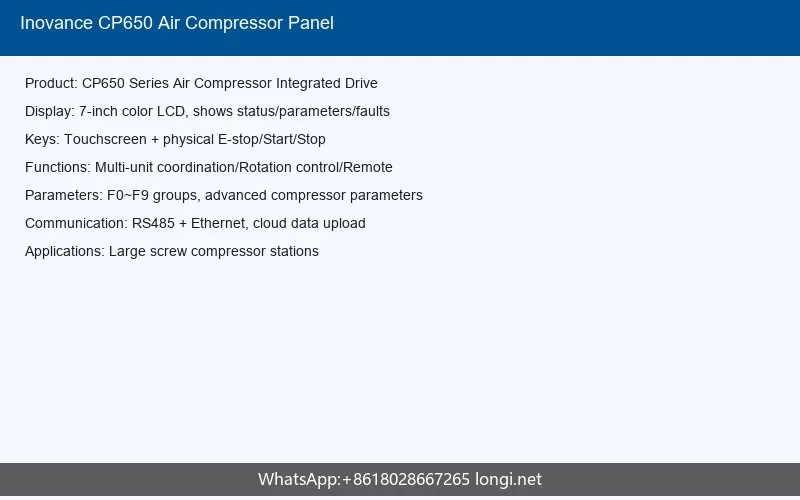
The CP650 does not use a traditional detachable LCD keypad. Instead, it features an integrated Human-Machine Interface (HMI) accessible through the drive cover, combined with three status LED indicators. The HMI is used during commissioning to set up motor parameters, pressure thresholds, and maintenance intervals. Once configured, the drive operates autonomously based on terminal signals and pressure feedback.
LED Status Indicators
Three front-panel LEDs provide at-a-glance status information:
| LED | Color | State | Meaning |
|---|---|---|---|
| POWER | Green | Steady on | Control board powered; DC bus voltage detected |
| RUN | Green | Steady on | Inverter is outputting and motor is running |
| FAULT | Red | Steady on | A fault has been triggered; motor stopped |
| FAULT | Red | Blinking | A warning (non-fatal) condition is active |
When the FAULT LED blinks rather than staying solid, the drive continues running but has detected a condition that requires attention, such as a maintenance interval reminder or a sensor reading approaching its threshold. Technicians should consult the HMI or communication interface to identify the specific warning code.
HMI Commissioning Flow
The HMI commissioning process follows a guided sequence. After powering on, the technician enters the motor nameplate data (rated power, voltage, current, frequency, and speed) into the F1 parameter group, then performs a motor auto-tuning procedure. This is critical because the CP650 uses sensorless vector control for optimal torque production across the speed range. Once the motor parameters are tuned, the air compressor-specific settings in the F0 and F6 groups are configured, including the target pressure, load/unload frequencies, and acceleration/deceleration times.
Main Circuit Terminal Wiring
Power Input and Motor Output
The main circuit terminals on the CP650 are organized into three functional groups:
| Terminal | Function | Notes |
|---|---|---|
| R, S, T | Three-phase AC input (or R, S for single-phase models) | Connect through a molded-case circuit breaker and input contactor |
| U1, V1, W1 | Inverter output to motor | Connected to the screw compressor motor terminals |
| U2, V2, W2 | Bypass output (direct line power) | Used when the motor must run directly from mains without inverter control |
| P+, P- | DC bus terminals | For external braking resistor connection if needed |
The bypass output (U2/V2/W2) is a distinctive feature of the CP650’s all-in-one design. It allows the compressor motor to be started directly across the line in emergency situations, bypassing the inverter entirely. This is controlled by an internal bypass contactor that is commanded through a dedicated digital output or the HMI bypass activation function.
Input Protection Requirements
Each CP650 model requires specific upstream protection. The input circuit breaker should be rated at approximately 1.5 to 2 times the rated input current of the inverter. An input AC reactor is recommended for models 22 kW and above to reduce harmonic distortion and protect the DC bus capacitors from peak current stress. Input and output magnetic contactors should never be used to start or stop the motor during normal operation; they should only be energized when the drive is ready and de-energized after the motor has coasted to a complete stop.
Control Terminal Functions and Wiring
Digital Inputs (DI1 through DI3)
The CP650 provides three digital input terminals that can be assigned various functions through the F4 parameter group. Common configurations include:
- DI1 – Remote start/stop command (typically wired to a pressure switch or external controller)
- DI2 – Fault reset input (connected to a remote reset pushbutton)
- DI3 – Multi-stage pressure selection (switches between two preset pressure targets)
Each DI terminal is compatible with both PNP and NPN sourcing sensors by virtue of the shared COM terminal. The internal +24V supply provides up to 100 mA for powering external transducers and proximity switches. When wiring long cable runs (over 30 meters), use shielded twisted-pair cable and ground the shield at the drive end only to prevent noise-induced false triggering.
Analog Inputs: Pressure and Temperature Sensors
One of the key differentiators of the CP650 is its built-in support for pressure and temperature transducers, eliminating the need for external signal conditioning modules:
| Terminal Pair | Sensor Type | Signal Range | Typical Application |
|---|---|---|---|
| P1+, P1- | Pressure transducer | 4-20 mA or 0-10V | Compressor discharge pressure feedback |
| PT1+, PT2+ | PT100 RTD | 2-wire or 3-wire | Oil temperature monitoring |
The pressure sensor input (P1+/P1-) is the primary feedback signal for the built-in PID controller. The drive compares the measured discharge pressure against the target setpoint and adjusts the motor speed to maintain the desired pressure. The PT100 temperature input provides oil temperature monitoring, which triggers protection actions if the temperature exceeds configurable thresholds.
Relay Output (T1A, T1C)
The CP650 includes one programmable relay output, typically configured as a fault alarm contact. The relay contacts are rated for 250 VAC at 3 A (resistive load). Common configurations include:
- Fault alarm output (closes or opens when any fault is triggered)
- Run indicator (active while the motor is running)
- Load/unload status signal
- Maintenance reminder output
The relay function is selected through the F4 parameter group, and the contact behavior (normally open or normally closed in the de-energized state) can be configured to match the external alarm circuit design.
Communication Interface
The CP650 supports Modbus RTU communication via an RS485 port, accessible through an RJ45 connector on the control board. This allows integration with supervisory SCADA systems, compressor controllers, or IoT gateways. The communication parameters (baud rate, slave address, parity) are set in the F0 group. A standard Modbus register map provides read access to operating status, measured pressure, temperature, motor frequency, and fault codes, as well as write access to control commands and setpoint adjustments.
Key Parameter Groups
F0 Group: Basic Operating Parameters
The F0 group contains the fundamental operating settings that define how the drive starts, stops, and regulates speed. Key parameters include the command source selection (terminal, HMI, or communication), the main frequency source (analog input, fixed preset, or PID output), the maximum and minimum output frequency limits, and the acceleration and deceleration times. For most air compressor applications, the command source is set to terminal control, and the frequency source is set to the internal PID controller output, which uses the pressure sensor feedback.
F1 Group: Motor Parameters
Accurate motor parameter entry is essential for sensorless vector control performance. The F1 group accepts the rated motor power, voltage, current, frequency, and rotational speed from the motor nameplate. After entering these values, a static or rotational auto-tuning procedure should be performed. Static tuning measures the stator resistance, leakage inductance, and mutual inductance without rotating the motor, while rotational tuning additionally measures the rotor flux and produces more accurate results but requires the motor to be uncoupled from the compressor load.
F4 Group: Digital Input/Output Configuration
The F4 group defines the function assigned to each digital input and the relay output. Each DI terminal can be assigned a function code from a predefined list. The most commonly used function codes for air compressor applications include:
- Function 1: Forward run command
- Function 4: Fault reset
- Function 7: Multi-speed selection
- Function 58: PTC thermal protection input (for monitoring external motor thermistor)
F6 Group: Start/Stop and Protection Logic
The F6 group governs the startup and shutdown behavior of the drive. This includes the start mode (direct start, speed tracking restart for spinning motors), stop mode (deceleration to stop or coast to stop), and stall protection settings. For air compressor applications, the speed tracking restart function is particularly valuable because it allows the drive to synchronize with a motor that is still spinning down from a previous run, avoiding the inrush current and mechanical stress associated with a direct restart.
F8 Group: Auxiliary Functions
The F8 group contains parameters for jog operation, multi-stage acceleration/deceleration time selection, jump frequencies, and energy-saving mode. Jump frequencies prevent the drive from operating continuously at frequencies that cause mechanical resonance in the compressor or piping system. The energy-saving mode optimizes the V/F pattern during light-load operation, reducing motor excitation current and saving energy during unload cycles.
Maintenance and Service Parameters
The CP650 incorporates a comprehensive maintenance tracking system that monitors the cumulative running hours of critical compressor components. When a component’s running time reaches its configured service interval, the drive generates a warning code (A76 through A80) prompting the operator to perform maintenance. The tracked components include:
| Warning Code | Component | Typical Service Interval |
|---|---|---|
| A76 | Air filter | 2,000-4,000 hours |
| A77 | Oil filter | 2,000-4,000 hours |
| A78 | Oil separator | 4,000-8,000 hours |
| A79 | Motor grease | 4,000-10,000 hours |
| A80 | Lubricating oil | 4,000-8,000 hours |
After performing maintenance on a component, the corresponding running hour counter must be cleared through the HMI or communication interface. Failure to reset the counter will result in the warning persisting even after the maintenance has been completed.
Fault Code Reference and Troubleshooting
Overcurrent and Overvoltage Faults
Overcurrent and overvoltage faults are the most commonly encountered issues in variable frequency drive operation. The CP650 distinguishes between acceleration, deceleration, and steady-state conditions to help pinpoint the root cause.
| Code | Description | Common Causes | Recommended Action |
|---|---|---|---|
| Err02 | Overcurrent during acceleration | Short acceleration time; motor parameters incorrect; load too heavy | Extend acceleration time; verify motor parameters; check compressor unloaded during start |
| Err03 | Overcurrent during deceleration | Short deceleration time; regenerative energy from compressed air | Extend deceleration time; install braking resistor |
| Err04 | Overcurrent at constant speed | Load surge; short circuit in motor cable | Inspect motor and cable insulation; check for sudden load changes |
| Err05 | Overvoltage during acceleration | Input voltage too high; regeneration during accel | Check input voltage; verify power supply stability |
| Err06 | Overvoltage during deceleration | Deceleration time too short; no braking resistor | Extend deceleration time; install braking unit and resistor |
| Err07 | Overvoltage at constant speed | Input voltage fluctuation; load regeneration | Stabilize input power; check for load-driven regeneration |
Overload and Overheat Faults
| Code | Description | Common Causes | Recommended Action |
|---|---|---|---|
| Err09 | Drive overload | Motor load exceeds drive capacity; incorrect drive sizing | Reduce load; verify drive is correctly sized for motor |
| Err10 | Motor overload (electronic thermal) | Motor running above rated current for extended period | Check for restricted air flow; verify pressure settings; inspect compressor valves |
| Err11 | Motor overload (PTC) | Motor temperature exceeded safe limit | Check motor cooling; reduce duty cycle; verify PTC wiring |
| Err13 | Inverter heatsink overheat | Ambient temperature too high; cooling fan failure; blocked air path | Reduce ambient temperature; replace fan; clean dust from heatsink |
Sensor and Protection Faults
| Code | Description | Common Causes | Recommended Action |
|---|---|---|---|
| Err74 | Pressure sensor disconnection | Broken sensor wire; faulty pressure transducer | Check wiring continuity; replace pressure sensor |
| Err75 | Temperature sensor disconnection | Broken PT100 wire; faulty temperature sensor | Check wiring; replace temperature sensor |
| Err81 | PTC2 overheat (fan motor) | Fan motor overheating; PTC wiring on DI5 incorrect | Check fan motor; verify DI5 function set to 58; if no fan PTC, set DI5 function to 0 |
| Err82 | Secondary separator blockage | Separator element clogged; DI terminal misconfigured | Clean or replace separator; check DI function settings |
| Err83 | Separator blockage | Oil separator element clogged; DI terminal misconfigured | Clean or replace separator; check DI function settings |
| Err84 | Oil filter blockage | Oil filter element clogged; DI terminal misconfigured | Replace oil filter; check DI function settings |
| Err85 | Air filter blockage | Air filter element clogged; DI terminal misconfigured | Replace air filter; check DI function settings |
Communication and System Faults
| Code | Description | Common Causes | Recommended Action |
|---|---|---|---|
| Err45 | External equipment fault | External safety circuit tripped; DI fault input triggered | Check external interlock circuit; verify DI fault input wiring |
| Err58 | RS485 communication fault | Communication cable broken; baud rate mismatch; slave address conflict | Check cable continuity; verify communication parameters; check for address conflicts |
Warning Codes (Non-Fatal Alerts)
Warning codes are prefixed with “A” rather than “Err” and indicate conditions that do not immediately stop the motor but require attention. The CP650 generates warnings for conditions approaching protection thresholds and for scheduled maintenance reminders.
| Code | Description | Action Required |
|---|---|---|
| A65 | Motor overload warning | Load approaching thermal limit; reduce duty or inspect compressor |
| A68 | Heatsink overheat warning | Cooling efficiency degrading; check fan and ventilation |
| A70 | Pressure 1 over-limit warning | Discharge pressure approaching maximum; check pressure settings |
| A73 | Temperature sensor 1 warning | Oil temperature approaching threshold; check cooling system |
| A76-A80 | Maintenance interval reminders | Perform scheduled service on the indicated component |
Best Practices for Commissioning and Operation
Pre-Power Checks
Before applying power for the first time, verify that all input and output power cables are correctly connected and torqued to specification. Confirm that the motor nameplate data has been accurately entered into the F1 parameter group. Check that the pressure sensor range matches the configured full-scale value, and that the sensor wiring polarity is correct. Inspect all control terminal wiring for shorts to ground or to adjacent terminals.
First Startup Procedure
During initial commissioning, start the compressor in an unloaded condition (open discharge valve or isolated from the air system). Perform the motor auto-tuning procedure with the motor uncoupled if possible, or in static mode if the motor cannot be uncoupled. After tuning, set the target pressure and pressure control PID parameters, then gradually load the compressor while monitoring the pressure response. Adjust the PID gains if the pressure overshoots or oscillates: increase the proportional gain to speed up response, increase the integral time to reduce steady-state error, and add derivative action to dampen oscillation.
Routine Inspection
During normal operation, periodically inspect the drive for unusual noises, odors, or excessive heat. Check that the cooling fan is operating and that the air intake and exhaust paths are unobstructed. Monitor the HMI for any warning codes and address them before they escalate into faults. Record the cumulative running hours and plan maintenance activities according to the service intervals configured in the maintenance parameters.
Conclusion
The Inovance CP650 series all-in-one air compressor inverter offers a tightly integrated solution that simplifies the electrical design of screw compressor systems while providing advanced control and protection features. By understanding the operation panel indicators, correctly wiring the main circuit and control terminals, configuring the key parameter groups for the specific application, and knowing how to interpret and respond to fault and warning codes, technicians can ensure reliable and efficient compressor operation over the long service life of the equipment. The built-in maintenance tracking system further reduces the risk of unexpected downtime by providing advance notice of required service activities, making the CP650 a well-rounded choice for industrial compressed air applications.