
Abstract
ABB soft starters are widely used in industrial motor control systems for applications requiring reduced starting current, smooth acceleration, controlled stopping, and motor protection. As one of the most important internal components, the power supply board plays a critical role in converting incoming AC power into multiple stable DC voltages required by the control system, trigger circuits, communication modules, relays, and monitoring circuits.
When the power supply board fails, the soft starter may experience various problems, including internal fault alarms, failure to start, communication errors, unstable operation, or protection trips. Unlike obvious failures such as damaged thyristor modules or burned power components, power supply board failures are often hidden and require systematic troubleshooting.
This article analyzes a real-world failure case involving an ABB soft starter power supply board model 1SFB536268D1007. A batch of replacement power boards was purchased, but one unit generated a fault after installation by the customer. Through analysis of the board structure, switching power supply design, common failure mechanisms, and practical diagnostic procedures, this article provides a comprehensive troubleshooting method for industrial engineers and repair technicians.
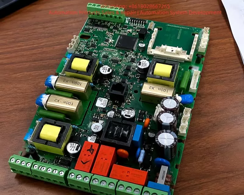
1. The Importance of the Power Supply Board in ABB Soft Starters
In industrial maintenance, engineers usually focus on the main power components when a soft starter fails:
- Thyristor modules;
- Main control board;
- Motor condition;
- Three-phase input power;
- Bypass contactor.
However, many real-world failures originate from the power supply board.
Modern ABB soft starters are not simple power switching devices. They contain a complete embedded control system consisting of:
- Microprocessor control;
- Current measurement circuits;
- Trigger pulse generation;
- Communication interfaces;
- Protection monitoring;
- Relay outputs;
- User interface circuits.
The power supply board provides the necessary electrical energy for all these systems.
A simplified structure is:
Three-phase AC Input
          |
          |
  Power Semiconductor Section
          |
          |
        Motor


Control System:

Power Supply Board
          |
          +---- CPU Control
          |
          +---- Thyristor Trigger Circuit
          |
          +---- Current Detection
          |
          +---- Communication Module
          |
          +---- Relay Output
The power supply board can therefore be considered the “energy center” of the soft starter.
If any output voltage becomes unstable, the entire soft starter may malfunction even when the main power components are completely healthy.
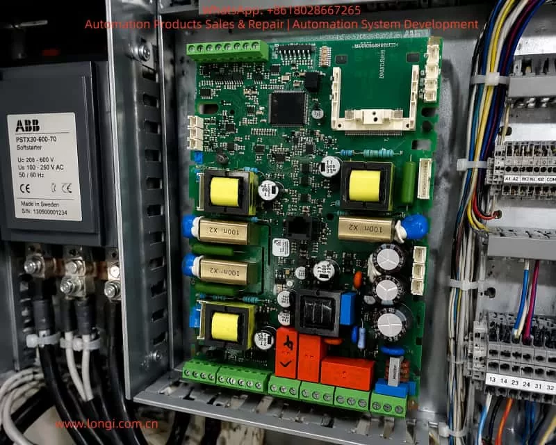
2. Structural Analysis of ABB 1SFB536268D1007 Power Supply Board
Based on the physical inspection of the 1SFB536268D1007 board, it adopts a typical industrial multi-output isolated switching power supply design.
The main functional sections include:
- AC input filtering and rectification;
- High-frequency switching conversion;
- Isolation transformer circuits;
- Multiple DC voltage outputs;
- Control interface circuits;
- Relay and auxiliary power circuits.
2.1 AC Input and Rectifier Section
The input section is usually located near the high-voltage side of the PCB.
Typical components include:
- EMI filter components;
- Surge protection devices;
- Safety capacitors;
- Rectifier bridge;
- High-voltage electrolytic capacitors.
The main function is:
Convert AC input into a stable DC bus voltage.
The conversion process is:
AC Input
   |
   |
EMI Filtering
   |
   |
Rectification
   |
   |
High Voltage DC Bus
This section directly faces industrial electrical environments, including:
- Voltage surges;
- Lightning impulses;
- Switching transients;
- Grid disturbances.
Therefore, it is one of the areas most vulnerable to damage.
2.2 High-Frequency Isolation Switching Power Supply Section
The board contains several yellow magnetic components visible on the PCB.
These are not traditional low-frequency transformers. They are high-frequency isolation transformers used in switching power supplies.
Their function is:
Convert high-voltage DC into several isolated low-voltage supplies.
Typical conversion process:
High Voltage DC
        |
        |
PWM Controller
        |
        |
High Frequency Transformer
        |
        +---- +5V
        |
        +---- +12V
        |
        +---- +15V
        |
        +---- +24V
Different circuits inside the soft starter require different supply voltages.
Typical applications:
| Voltage | Application |
|---|---|
| +5V | CPU and logic circuits |
| +3.3V | Digital control system |
| +15V | Trigger and driver circuits |
| +24V | Relays and external interfaces |
If any of these voltages becomes abnormal, the soft starter may generate an internal fault.
2.3 Control Interface Section
The upper connectors and terminal blocks connect the power supply board with:
- Main control PCB;
- External control terminals;
- Communication modules;
- Feedback detection circuits.
A power supply board may appear to work normally, but abnormal interface signals can still cause:
- Start command failure;
- Communication errors;
- Internal protection alarms.
3. Why One Replacement Board Failed After Installation
In practical industrial repair, it is common to encounter this situation:
“A customer receives several replacement boards. Most work normally, but one board produces a fault after installation.”
This does not necessarily indicate installation error.
Several causes should be considered.
3.1 Aging During Long-Term Storage
Electronic components can deteriorate even without operation.
The most common aging component is the electrolytic capacitor.
Electrolytic capacitors may experience:
- Reduced capacitance;
- Increased ESR;
- Increased ripple current;
- Reduced filtering performance.
For example:
Normal capacitor:
470uF
ESR = 0.05Ω
Aged capacitor:
470uF
ESR = 2Ω
A capacitance meter may still show an acceptable value, but the switching power supply may become unstable.
Typical symptoms:
- Starts normally when cold;
- Fault occurs after several minutes;
- Voltage drops under load.
3.2 Switching Power Supply Feedback Failure
A switching power supply depends on a feedback loop consisting of:
- PWM controller;
- Optocoupler;
- TL431 reference circuit;
- Feedback resistors.
If the feedback loop fails:
Output voltage may increase
Example:
24V output becomes 30V.
Possible consequences:
- Downstream IC damage;
- Protection activation;
- Control malfunction.
Output voltage may decrease
Example:
24V output drops to 18V.
Possible consequences:
- Relay cannot energize;
- CPU resets;
- Communication failure.
3.3 Incorrect Input Voltage Version
Industrial equipment often has multiple voltage versions.
The same soft starter series may include:
- 110VAC control supply version;
- 230VAC version;
- 400VAC version.
If the installed power board does not match the equipment voltage configuration, abnormal operation may occur.
For example:
Equipment designed for:
230VAC control supply
but connected to:
400VAC supply
may result in:
- Immediate fault;
- Component overheating;
- Permanent damage.
Therefore, checking the equipment nameplate before replacement is essential.
3.4 The Soft Starter Itself May Cause the Fault
A common mistake during troubleshooting is assuming:
“New power board = guaranteed good.”
This is not always true.
The original soft starter may have another hidden problem:
- Damaged thyristor module;
- Short circuit in trigger circuit;
- Abnormal load;
- Damaged bypass circuit.
The new power board may simply expose the existing system problem.
4. Standard Troubleshooting Procedure for ABB Soft Starter Power Boards
Step 1: Confirm Whether the Fault Follows the Board
If multiple identical boards are available, perform a comparison test.
Example:
Soft starter A:
Install board No.1:
Fault occurs.
Install board No.2:
Works normally.
Conclusion:
Board No.1 has a high probability of failure.
If all boards fail:
The problem is likely in the soft starter system.
Step 2: Verify Input Voltage
Measure the actual voltage supplied to the power board.
Record:
Input Voltage:
Frequency:
Connection Method:
Do not only confirm that voltage exists.
Industrial electronics require:
- Correct voltage level;
- Stable waveform;
- Correct frequency.
Step 3: Measure DC Output Voltages
The most important measurements are:
| Test Point | Normal Range |
|---|---|
| +5V | 4.8–5.2V |
| +15V | 14–16V |
| +24V | 22–26V |
Fault examples:
5V normal, 24V abnormal
The problem is likely in the 24V secondary circuit.
All outputs abnormal
The primary switching section should be investigated.
Step 4: Check Output Ripple
Many technicians only measure DC voltage.
However, switching power supplies must also be checked for ripple.
Example:
A multimeter shows:
24V DC
but an oscilloscope reveals:
3V peak-to-peak ripple
The system may still malfunction.
Recommended oscilloscope measurements:
- 5V ripple;
- 15V ripple;
- 24V ripple.
Step 5: Inspect Critical Components
Electrolytic Capacitors
Check:
- Leakage;
- Bulging;
- ESR value;
- Temperature condition.
Optocouplers
Check:
- LED input side;
- Output transistor switching.
PWM Controller
Check:
- Startup voltage;
- Switching waveform;
- Drive signal.
Power MOSFET
Check:
- Drain-source short circuit;
- Gate abnormality;
- Leakage current.
5. Common Fault Symptoms and Diagnostic Direction
Symptom 1:
No Display After Power-On
Possible causes:
- Input fuse failure;
- Switching power supply startup failure;
- Primary MOSFET damage.
Inspection:
Check whether the high-voltage DC bus exists.
Symptom 2:
Display Works but Motor Cannot Start
Possible causes:
- Insufficient 24V supply;
- Relay failure;
- Trigger supply abnormality.
Symptom 3:
Internal Fault Alarm
Possible causes:
- Unstable power supply;
- CPU supply reset;
- Communication voltage abnormality.
Symptom 4:
Bypass Fault
Focus inspection on:
- Relay circuit;
- Bypass control;
- Feedback detection.
6. Repair Recommendations for ABB Power Supply Boards
6.1 Replace Aging Capacitors Correctly
Do not select capacitors only according to capacitance.
Important specifications:
- Voltage rating;
- Temperature rating;
- ESR;
- Ripple current capability.
Industrial applications should use:
- 105°C capacitors;
- High-frequency switching capacitors.
6.2 Perform Load Testing After Repair
A repaired power board should not only pass no-load testing.
Recommended testing:
- 25% load;
- 50% load;
- 75% load;
- 100% load.
Monitor:
- Output voltage stability;
- Temperature rise;
- Alarm conditions.
6.3 Avoid Blind Component Replacement
Replacing random ICs without measurement usually increases repair difficulty.
The correct approach is:
Fault Alarm
     |
Confirm Model
     |
Measure Input
     |
Measure Output
     |
Compare Good Board
     |
Locate Circuit Section
     |
Replace Failed Component
     |
Load Verification
7. Practical Lessons from Industrial Repair Experience
The ABB 1SFB536268D1007 power supply board failure case demonstrates an important principle:
Small electronic modules can determine the reliability of an entire industrial control system.
When dealing with replacement or refurbished boards, engineers should consider:
- Storage aging;
- Capacitor degradation;
- Hidden power supply instability;
- Compatibility issues;
- Secondary equipment faults.
A professional repair process should include:
- Visual inspection;
- Electrical measurement;
- Functional comparison;
- Component-level diagnosis;
- Final operational testing.
8. Conclusion
The ABB soft starter power supply board 1SFB536268D1007 is a critical component responsible for supplying stable energy to the entire control system. Although it is not the main power switching element, its failure can completely disable the soft starter.
When a replacement board generates faults after installation, engineers should not immediately assume that the board is correct or that the customer installation is wrong. A systematic diagnostic approach is required:
- Verify the soft starter model;
- Confirm the alarm code;
- Check input voltage;
- Measure all DC outputs;
- Analyze switching power supply circuits;
- Inspect capacitors, feedback circuits, and switching devices;
- Perform load testing.
Through structured troubleshooting and board-level repair methods, ABB soft starter power supply failures can be accurately identified and repaired, reducing downtime and avoiding unnecessary replacement costs in industrial automation systems.