
Abstract
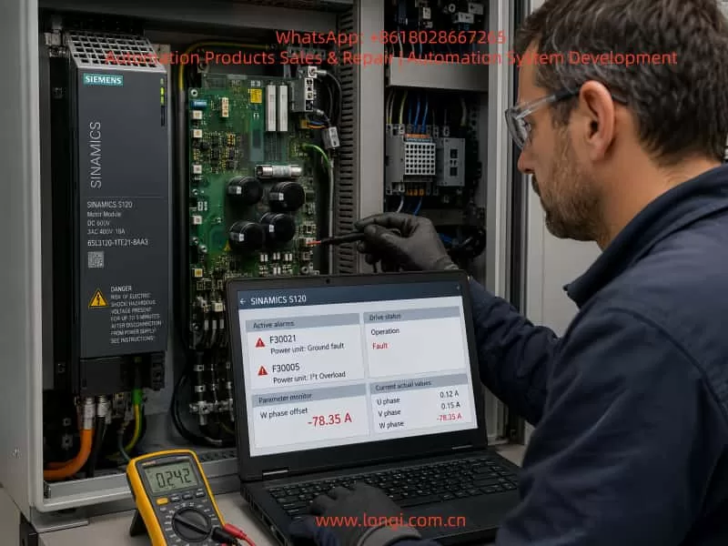
Siemens SINAMICS S120 drive systems are widely used in high-performance industrial applications, including CNC machines, robotics, printing equipment, semiconductor manufacturing, packaging systems, and other precision automation fields. Due to their advanced modular power structure, SINAMICS S120 power units have very strict requirements for power semiconductors, current measurement circuits, gate drive circuits, and protection feedback systems.
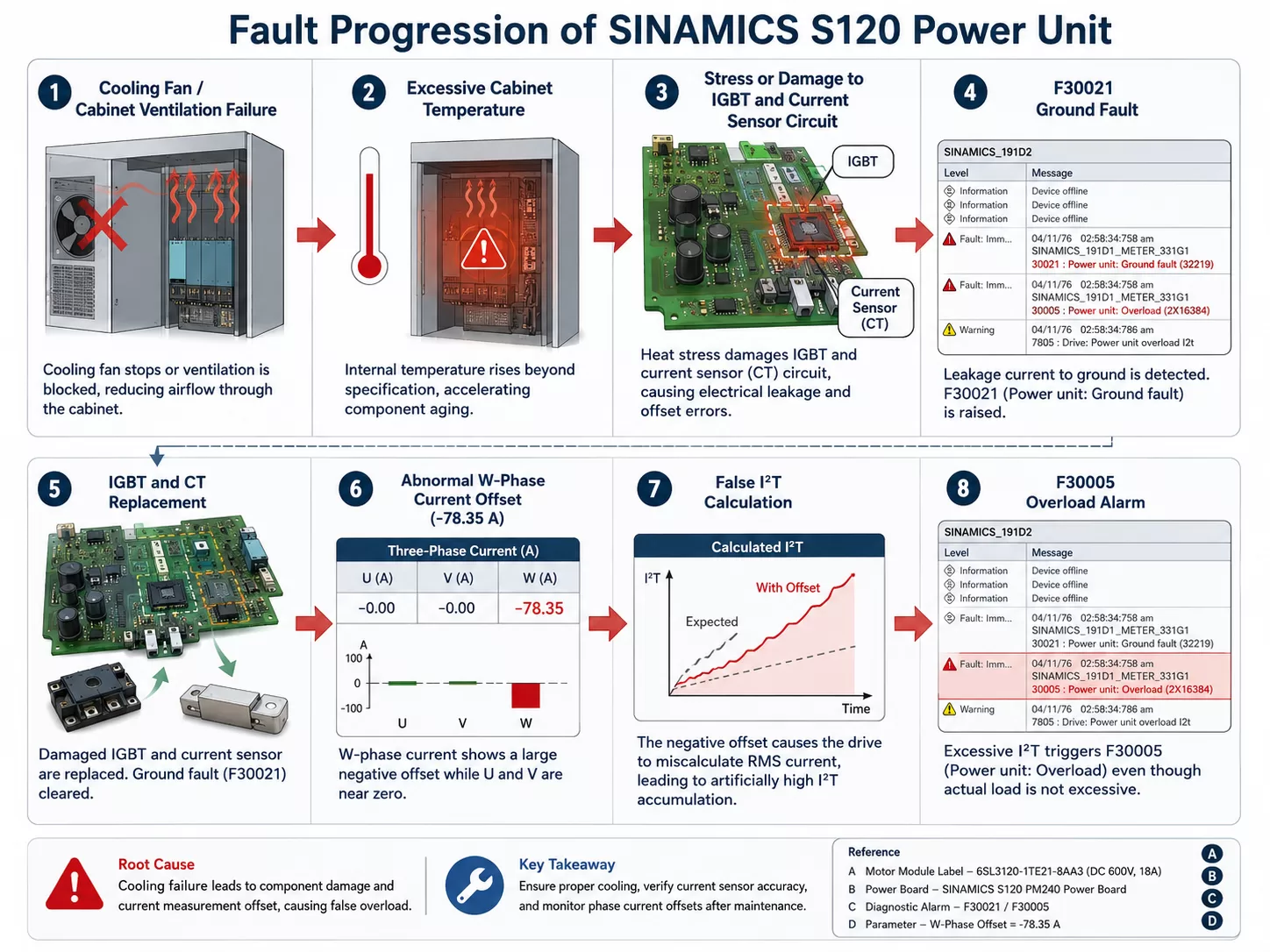
During field maintenance, one of the most challenging situations is when a SINAMICS S120 Motor Module experiences a severe overheating event caused by cabinet cooling failure. After the internal cabinet temperature rises abnormally, the drive may report faults such as:
- F30021 – Power unit: Ground fault
- F30005 – Power unit: Overload I²T
In many repair cases, technicians replace major power components, including:
- IGBT power modules
- Current transformers (CT sensors)
- Internal fuses
However, after replacement, the drive still reports F30005 shortly after power-up. The drive may start normally when cold, but after approximately one minute the alarm appears again.
A typical example is:
- SINAMICS S120 Motor Module
- Model: 6SL3120-1TE21-8AA3
- Rated output: 3AC 400V / 18A
- DC link voltage: 600V
After IGBT and CT replacement, the diagnostic parameter shows:
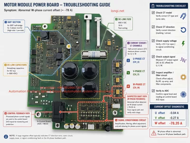
Phase U offset: -0.04 A
Phase V offset: -0.27 A
Phase W offset: -78.35 A
This abnormal W-phase current offset becomes the key evidence. It indicates that the actual problem is most likely not the IGBT itself, but a failure inside the current feedback measurement circuit.
This article explains the causes, diagnostic methods, and repair strategy for SINAMICS S120 F30005/F30021 faults, using this case as a practical example.
1. Overview of SINAMICS S120 Motor Module Structure
1.1 Basic Power Structure
The SINAMICS S120 system is based on a modular drive architecture. A typical configuration consists of:
Three-phase AC Supply

        ↓

Line Module

        ↓

DC Link 600V

        ↓

Motor Module

        ↓

IGBT Inverter Bridge

        ↓

U/V/W Output

        ↓

Motor
Inside the Motor Module, several critical circuits work together:
- IGBT power switching stage
- Gate driver circuit
- DC-link voltage monitoring
- Three-phase current measurement
- Temperature monitoring
- Short-circuit protection
- Ground fault detection
A failure in any of these circuits can generate power unit faults.
2. Understanding SINAMICS S120 Fault F30021
2.1 Meaning of F30021
Fault code:
F30021 – Power unit: Ground fault
is usually interpreted as:
The power unit has detected an abnormal leakage current or ground fault condition.
Many technicians immediately assume:
- Motor insulation failure
- Motor cable short circuit
- IGBT breakdown
These are possible causes, but they are not the only causes.
The SINAMICS S120 does not simply measure insulation resistance to determine this fault. Instead, it uses:
- Phase current feedback
- Current vector calculation
- Power stage protection algorithms
The drive continuously checks the relationship between the three-phase output currents:
IU + IV + IW = 0
Under normal conditions:
IU = 10A
IV = 10A
IW = 10A
The system is balanced.
However, if the current measurement circuit is incorrect:
IU = 10A
IV = 10A
IW = 80A
The controller may interpret this imbalance as abnormal leakage current and trigger F30021.
Therefore:
A false current feedback signal can also create a ground fault alarm.
3. Understanding SINAMICS S120 Fault F30005
3.1 What Does I²T Overload Mean?
Fault:
F30005 – Power unit: Overload I²T
does not always mean that the motor is mechanically overloaded.
I²T protection is a thermal protection model.
The principle is:
Thermal stress = Current² × Time
A small current increase over a long period can accumulate enough thermal stress to trigger protection.
For example:
At 10A:
10² = 100
At 50A:
50² = 2500
The thermal effect increases dramatically.
The drive calculates the estimated thermal stress of the power module. When the calculated value exceeds the permitted limit, F30005 occurs.
4. Why Does F30005 Appear One Minute After Power-On?
This timing information is extremely important.
If the IGBT is completely shorted:
- Fault usually appears immediately.
- The drive trips instantly.
- F30021 normally occurs very quickly.
However, in this case:
- Drive starts normally when cold.
- After about one minute:
- Only F30005 appears.
This indicates a protection calculation process.
The possible sequence is:
Power ON

↓

Power unit initialization

↓

Current feedback activated

↓

Abnormal current offset detected

↓

Software calculates excessive thermal stress

↓

I²T value increases

↓

F30005 occurs
This behavior strongly suggests:
incorrect current feedback rather than a real overload condition.
5. The Critical Diagnostic Data: W Phase Offset -78.35A
The most important diagnostic information in this case is:
Phase current offset:

U phase:
-0.04 A

V phase:
-0.27 A

W phase:
-78.35 A
The Motor Module rating:
Output current: 18A
But the measured W-phase offset:
-78.35A
is more than four times the rated output current.
This is absolutely abnormal.
A healthy current measurement system normally has:
- Offset close to 0A
- Small differences between phases
- Usually within a fraction of an ampere
A value of -78A means:
The drive believes that W-phase current exists even when the motor is not running.
6. Fault Location Analysis
Based on the diagnostic results:
| Component | Evaluation |
|---|---|
| U-phase current measurement | Normal |
| V-phase current measurement | Normal |
| W-phase current measurement | Abnormal |
| Motor | Lower probability |
| DC-link capacitor | Possible but not primary |
| IGBT | Already replaced |
| Software parameter | Low probability |
The fault area is concentrated in the W-phase current feedback path:
W-phase CT sensor

↓

CT power supply

↓

CT output signal

↓

Filtering circuit

↓

Amplifier circuit

↓

ADC input

↓

Control electronics
7. Why Did the Overheating Event Damage the Current Measurement Circuit?
The original failure was caused by:
Cabinet cooling fan failure and excessive internal temperature.
Many repairs focus only on replacing:
- IGBT
- Fuse
However, overheating affects many other components.
7.1 Current Sensor Damage
The CT sensor may contain:
- Hall sensor element
- Signal conditioning circuit
- Temperature compensation components
High temperature can cause:
- Zero-point drift
- Sensitivity change
- Output instability
7.2 Analog Circuit Damage
Behind the CT sensor there are usually:
- Filtering resistors
- Capacitors
- Operational amplifiers
- Protection components
High temperature can cause:
- Resistor value drift
- Capacitor leakage
- Amplifier input damage
7.3 Secondary Damage from IGBT Failure
When an IGBT fails:
The fault current path can be:
IGBT failure

↓

DC bus current surge

↓

Current sensor

↓

Measurement circuit
Even if the IGBT is replaced successfully, the current feedback circuit may remain damaged.
8. Why Replacing the CT Sensor May Not Solve the Problem
Replacing the CT sensor does not guarantee repair.
The following points must be confirmed:
8.1 Correct CT Model
The replacement CT must have:
- Same model number
- Same sensitivity
- Same output characteristics
- Same temperature compensation
A physically identical sensor may still be electrically different.
8.2 Correct Installation Direction
Hall current sensors are directional.
Incorrect installation can cause:
- Negative output
- Incorrect polarity
- Large current offset
8.3 Correct Wiring
The following must be verified:
- Positive supply
- Negative supply
- Signal output
- Ground connection
8.4 Calibration Requirements
After replacing power components, some systems may require:
- Current offset calibration
- Drive identification procedure
Otherwise, the current measurement may remain incorrect.
9. Recommended Troubleshooting Procedure
Step 1: Disconnect Motor Cable
Remove:
U
V
W
from the motor.
Purpose:
Eliminate:
- Motor insulation problems
- Cable short circuit
Step 2: Check Current Offset Parameters
Monitor:
r0069[3]  Phase U offset

r0069[4]  Phase V offset

r0069[5]  Phase W offset
The three values should be close to each other.
A difference of tens of amperes indicates a measurement circuit failure.
Step 3: Measure CT Supply Voltage
Compare:
- U-phase CT
- V-phase CT
- W-phase CT
Measure:
- Supply voltage
- Ground reference
- Output voltage
All three channels should be similar.
Step 4: Check CT Output Signal
With zero current:
The CT output should remain stable.
If W-phase output is:
- 0V
- 5V
- unstable voltage
the sensor or signal circuit is faulty.
Step 5: Inspect PCB Components
Focus on the W-phase measurement area:
- Solder joints
- Signal resistors
- Filter capacitors
- Operational amplifier
- PCB traces
High-current IGBT failures often leave hidden damage.
10. Common Repair Mistakes
Mistake 1: Only Replacing IGBT
Many technicians see F30021 and immediately replace IGBT.
However:
The IGBT may only be the damaged component, not the root cause.
Mistake 2: Ignoring Current Feedback
Modern drives depend heavily on feedback signals.
Incorrect feedback can create:
- False overcurrent
- False ground fault
- False thermal overload
Mistake 3: Not Checking Diagnostic Parameters
SINAMICS S120 provides detailed diagnostic information:
Examples:
- r0069 current feedback
- r0949 fault values
- Fault history
Ignoring these parameters makes troubleshooting much more difficult.
11. Final Diagnosis of This Case
Considering all information:
- Cabinet cooling failure caused overheating.
- Initial faults were F30021 and F30005.
- IGBT was replaced.
- CT sensors were replaced.
- Fault still appears after approximately one minute.
- W-phase current offset is -78.35A.
The most likely causes are:
First possibility: W-phase current sensing failure
Probability: approximately 50%
Possible reasons:
- Incorrect CT installation
- Wrong CT replacement model
- Damaged W-phase CT
- CT power supply failure
Second possibility: W-phase analog feedback circuit damage
Probability: approximately 35%
Possible components:
- Signal resistor
- Filter capacitor
- Operational amplifier
- ADC input circuit
Third possibility: IGBT driver circuit problem
Probability: approximately 15%
12. Conclusion
SINAMICS S120 F30005 and F30021 faults should not be diagnosed only by replacing power semiconductors.
In high-power industrial drives, the real failure may exist in:
- Current sensing circuits
- Gate driver circuits
- Protection feedback systems
In this case, the most valuable diagnostic information is:
Phase W offset = -78.35A
This proves that the drive detects a huge W-phase current even without normal motor operation.
The correct repair approach is not simply:
Replace IGBT again.
Instead, the troubleshooting path should follow:
Power semiconductor

↓

Gate driver

↓

Current sensor

↓

Signal conditioning circuit

↓

Control feedback
By analyzing the current feedback system, technicians can accurately locate the fault, prevent repeated IGBT failures, and significantly improve the repair success rate of Siemens SINAMICS S120 Motor Modules.