
Introduction
In large-scale hydro-cooled mining facilities, Antminer S19 XP Hyd. and S19 XP+ Hyd. miners are commonly installed in groups and operated through centralized power distribution and cooling systems. Compared with conventional air-cooled miners, hydro-cooled models eliminate high-speed cooling fans and instead rely on circulating coolant, internal cold plates, pumps, heat exchangers, manifolds, and external cooling equipment to remove heat generated by the ASIC chips.
This architecture offers several advantages, including lower acoustic noise, improved power density, and better thermal performance in demanding environments. However, it also introduces a more complex fault chain. A hydro-cooled miner does not judge its thermal condition simply from room temperature. Its control system continuously evaluates hashboard temperatures, PIC controller temperatures, power-supply communication, ASIC detection results, voltage regulation, frequency ramping, and several protection thresholds.
As a result, maintenance personnel can easily misdiagnose a machine when the miner log simultaneously displays messages such as:
get power version failed
check power version failed, use v2 protocol to try it again
ERROR_TEMP_TOO_HIGH
over max temp
power off hashboard
Some technicians immediately conclude that the power supply is defective after seeing “get power version failed.” Others focus only on the temperature alarm and check the ambient temperature. When the room temperature is found to be only 32–33°C, they may assume that the miner’s temperature-monitoring circuit is faulty.
In reality, these messages may appear during the same startup process but have different levels of importance. They may not have the same root cause, and they should not be assigned the same diagnostic priority.
The correct approach is to analyze the complete startup sequence of the miner and separate normal startup retries, compatibility warnings, recoverable communication events, and the final fault that actually caused the shutdown.
This article presents a systematic diagnostic method for Antminer S19 XP Hyd. and S19 XP+ Hyd. miners experiencing high-temperature shutdowns, power-version reading failures, EEPROM-version warnings, unsuccessful initialization, and interruptions during frequency ramping. The discussion is based on a practical multi-miner case involving both operating and stopped hydro-cooled units.
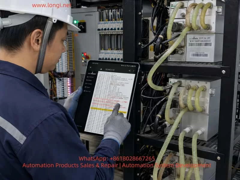
1. Basic System Architecture of a Hydro-Cooled Miner
A complete Antminer S19 XP Hyd. or S19 XP+ Hyd. system normally includes the following components:
- Control board
- Three hydro-cooled hashboards
- Dedicated miner power supply
- High-current copper busbars or equivalent power connections
- Power-supply communication cable
- Hashboard signal cables
- Coolant distribution manifold
- Internal cold plates and coolant channels
- Coolant inlet and return hoses
- External circulation pump
- Heat exchanger or cooling tower
- Flow, pressure, and temperature-monitoring devices
The control board performs several critical tasks. It boots the embedded Linux operating system, loads miner firmware, reads hashboard EEPROM data, identifies ASIC chips, communicates with the power supply, controls operating voltage and frequency, receives temperature data, and executes shutdown protection when abnormal conditions are detected.
The hashboards contain large numbers of ASIC chips. The exact ASIC count and operating frequency differ between S19 XP Hyd. and S19 XP+ Hyd. versions, but the overall control logic is similar: multiple chains operate together, and the miner must correctly detect and initialize each chain before normal hashing can begin.
The power supply is not merely a fixed-output DC source. The control board communicates with it digitally to obtain information such as:
- Power-supply version
- Serial number
- Calibration status
- Calibration data
- Output-voltage capability
- Watchdog status
- Current operating state
The control board also commands the power supply to raise or lower its output according to the miner’s operating frequency and workload.
The hydro-cooling system carries heat away from the ASIC chips and transfers it to the circulating coolant. The heat is then removed by an external radiator, heat exchanger, cooling tower, or other cooling device.
A failure in any one of these subsystems can prevent startup or cause a shutdown during operation.
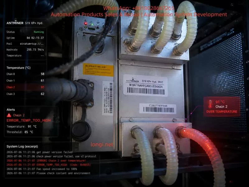
2. Why a Miner Can Report High Temperature When the Room Is Only 32–33°C
One of the most common misunderstandings in hydro-miner troubleshooting is the assumption that a high-temperature alarm refers directly to the room temperature.
For a hydro-cooled miner, room temperature is only one external condition. The protection algorithm primarily reacts to temperatures measured inside the miner.
A room temperature of 32°C does not guarantee that the hashboards are being cooled correctly. Similarly, an inlet coolant temperature of approximately 29–33°C does not prove that coolant is flowing properly through every cold plate.
The heat-transfer path is approximately:
ASIC junction
→ chip package
→ thermal interface material
→ cold plate
→ coolant
→ hose network
→ heat exchanger
→ surrounding environment
Any abnormal thermal resistance along this path can produce a local overtemperature condition.
Typical causes include:
- Internal blockage in one cold plate
- Air trapped inside a coolant channel
- A bent or compressed hose
- A quick connector that is not fully opened
- Uneven flow distribution among parallel branches
- Insufficient pump flow
- Excessively high coolant viscosity
- Contaminated coolant
- Scale or corrosion inside the cold plate
- Poor contact between the ASIC surface and cold plate
- Degraded thermal interface material
- Temperature-sensor drift
- Faulty PIC temperature acquisition
- Abnormal local power dissipation
Therefore, normal room temperature does not exclude a genuine internal overtemperature fault.
3. The Correct Way to Read the Miner Log
A miner log should be read as a chronological startup sequence. It should not be interpreted by selecting one alarming line and ignoring the events before and after it.
The startup process can generally be divided into seven stages.
4. Stage One: Control-Board System Startup
During the first stage, the embedded operating system initializes storage, memory, network interfaces, the FPGA, and the web server.
Typical log entries include:
UBIFS mounted
eth0: link becomes ready
start the http server
httpserver:6060 started ok
If the miner’s web interface can be accessed normally, the following components are probably functioning at a basic level:
- Main processor
- Flash storage
- Ethernet interface
- Operating system
- Web-management service
This does not prove that the control board is completely fault-free, but it makes a severe CPU, memory, or network failure less likely.
Boot messages such as file-system recovery, reserved block information, or kernel initialization are not necessarily faults. They are often standard system messages.
The important question is whether the system reaches the miner application and begins hardware initialization.
5. Stage Two: Detection of Hashboards and Chains
A normal startup may include:
board num = 3
board id = 0, chain num = 1
board id = 1, chain num = 1
board id = 2, chain num = 1
chain num = 3
This indicates that the control board recognizes three hashboards or three chains.
If only one or two chains are detected, possible causes include:
- Loose or damaged signal cable
- Control-board connector failure
- Missing auxiliary voltage on one hashboard
- PIC controller not starting
- Severe short circuit on the hashboard
- Incompatible firmware
- Corrupted board data
When all three chains are detected, the basic communication path is present. However, this does not prove that all chips are healthy or that the cooling system is working correctly.
6. Stage Three: Reading Hashboard EEPROM Data
The log may show:
load chain 0 eeprom data
version invalid 5!=4
v5 load data succ
This sequence is often misunderstood.
The message:
version invalid 5!=4
may simply indicate that the firmware first attempted to interpret the EEPROM using one data structure, found a different version number, and then retried with the correct version.
The following line:
v5 load data succ
shows that version-5 data was successfully loaded.
Therefore, the warning by itself does not prove that the EEPROM is damaged.
The message becomes more significant only if it is accompanied by errors such as:
eeprom read failed
crc error
invalid board data
cannot load eeprom
chain data missing
or if the miner fails to determine the correct model, ASIC count, voltage parameters, or target frequency.
In the case discussed here, all three chains reported “version invalid 5!=4” followed by successful version-5 data loading. This suggests a compatibility-handling process rather than a fatal EEPROM failure.
7. Stage Four: ASIC Chip Detection
A healthy S19 XP Hyd. chain may report:
Chain[0]: find 204 asic
Chain[1]: find 204 asic
Chain[2]: find 204 asic
When all three chains detect the full expected number of ASIC chips, several conclusions can be drawn:
- The control-board-to-hashboard communication is functioning.
- The clock signal reaches the ASIC chain.
- The reset path is functioning.
- Serial communication through the ASIC chain is intact.
- The PIC controller is operating sufficiently to support initialization.
- There is no obvious chip-chain break.
- No major number of chips is missing.
This does not guarantee that the hashboard is completely healthy. A board can still have a cooling fault, unstable voltage rail, marginal ASIC, thermal-sensor fault, or intermittent communication issue.
However, when all 204 ASICs are found on each chain, the probability of a classic “missing chip,” “broken chain,” or signal-line fault becomes much lower.
If a chain detects only part of the expected ASIC count, the technician should instead investigate:
- Clock signal
- Reset signal
- CO, RI, BO, or equivalent chain signals
- Local voltage domains
- Damaged ASICs
- Broken solder joints
- Shorted or open components
- Fault location within the chain
8. Stage Five: Communication With the Power Supply
The following sequence may appear:
get power version failed
check power version failed, use v2 protocol to try it again
power open power_version = 0x65
power is calibrated
power sn: XXXXX
enable_power_calibration
This must be interpreted as a complete sequence.
The first line:
get power version failed
means that the first attempt to read the power-supply version did not succeed.
The next line:
use v2 protocol to try it again
shows that the firmware changed its communication method and retried.
If the later log displays:
power open power_version = 0x65
power is calibrated
power sn: XXXXX
then the control board eventually obtained useful data from the power supply, including:
- Power type or version
- Serial number
- Calibration status
- Calibration record
In this situation, it is incorrect to declare that the power supply is completely dead.
More likely explanations include:
- The first handshake timed out.
- The firmware and PSU use different protocol revisions.
- The PSU started responding later than expected.
- The communication line has marginal contact.
- There is electrical interference.
- The PSU controller has a delayed initialization sequence.
- The firmware includes a compatibility fallback mechanism.
The severity of “get power version failed” depends on what happens next.
When the miner can later set voltage, detect ASICs, and ramp frequency, the power supply is clearly providing functional output. The message may still deserve attention, but it is not necessarily the direct cause of the shutdown.
9. When “Get Power Version Failed” Is a Serious Fault
The message becomes more important when the following conditions are also present:
get power version failed
power communication timeout
cannot read power SN
power init failed
and when:
- Hashboards do not receive operating voltage.
- ASIC detection never starts.
- Frequency ramping does not begin.
- The miner repeatedly restarts.
- The PSU does not respond to voltage commands.
- The PSU communication data remains completely unavailable.
In that case, the technician should inspect:
- PSU communication cable
- Connector pin contact
- Cable continuity
- Auxiliary supply voltage
- Control-board communication port
- PSU internal controller
- Firmware compatibility
- PSU model compatibility
- Grounding and electrical noise
However, that was not the primary pattern in the high-temperature case. The affected miners were still able to recognize all ASICs and begin frequency ramping.
10. Stage Six: Voltage Establishment and Frequency Ramping
A normal miner does not immediately start at full operating frequency. It usually increases voltage and frequency in controlled steps.
Typical entries include:
set_voltage_by_steps to 2100
Chain[0]: find 204 asic
Chain[1]: find 204 asic
Chain[2]: find 204 asic
chain 0 set freq to 50
chain 1 set freq to 50
chain 2 set freq to 50
...
chain 0 set freq to 475
chain 1 set freq to 475
chain 2 set freq to 475
The gradual ramp serves several purposes:
- Reduces inrush stress
- Tests ASIC stability at increasing frequency
- Confirms adequate operating voltage
- Monitors chip response
- Detects thermal abnormalities
- Allows the firmware to adjust voltage margins
- Prevents sudden excessive current demand
If the miner successfully ramps from approximately 50 MHz to 475 MHz, several subsystems are working:
- The PSU is supplying output power.
- The control board can command voltage changes.
- The ASIC chains respond to frequency commands.
- The hashboards are capable of operating at least during initialization.
- The signal paths are functioning.
This is strong evidence against a complete PSU failure.
In the analyzed case, the miner reached high frequency before the temperature protection occurred. Therefore, the final shutdown was not caused by an inability to power the hashboards.
11. Stage Seven: Final Protection Trigger
The decisive log lines were:
over max temp, pic temp(chain2) 81 (max 80)
ERROR_TEMP_TOO_HIGH
stop mining: over max temp
power off hashboard
This is the actual shutdown event.
The log provides four important facts:
- The problem occurred on Chain 2.
- The measured PIC-related temperature reached 81°C.
- The configured maximum was 80°C.
- The firmware intentionally shut down the hashboards.
Therefore, the direct reason for stopping was overtemperature protection.
The earlier power-version message was not the final shutdown command.
This distinction is essential. A miner log may contain multiple warnings, but only one event may actually cause the stop command.
12. Case Comparison Between Running and Stopped Miners
The site included multiple Antminer S19 XP Hyd. and S19 XP+ Hyd. miners.
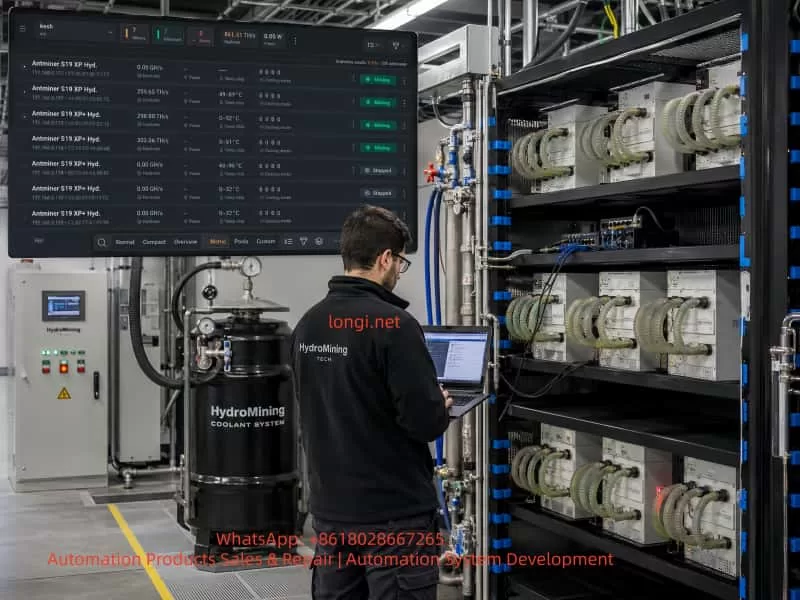
The monitoring interface showed a mixed operating condition:
- Some miners were producing approximately 259 TH/s.
- Some were producing approximately 298 TH/s.
- Some were producing approximately 303 TH/s.
- Several miners were stopped at 0 GH/s.
- One stopped miner showed a temperature range near 48–96°C.
- Another stopped miner showed 0–32°C.
- Different machines used different firmware compilation dates.
- Several machines reported similar EEPROM-version messages.
- Some machines reported initial PSU-version read failures.
This is important because it proves that the entire cooling and power-distribution system was not completely nonfunctional. Several miners were still hashing.
At the same time, it does not prove that every cooling branch was healthy. In a parallel hydro-cooling system, some machines can receive adequate coolant flow while others receive insufficient flow.
The correct diagnostic approach is therefore machine-specific. Each IP address must be analyzed separately.
It is a mistake to assume that all miners of the same model have the same fault merely because they are connected to the same cooling rack.
13. The Significance of the 81°C Chain-2 Alarm
The critical line was:
pic temp(chain2) 81 (max 80)
This does not mean that the room was 81°C. It does not necessarily mean that the bulk coolant reached 81°C. It means that the temperature value associated with Chain 2 and monitored by the firmware crossed the protection threshold.
The monitoring software also showed one miner with a displayed temperature range up to 96°C. This is consistent with a local thermal problem or a temperature-sensing abnormality.
Because the fault repeatedly involved a specific chain rather than all three chains simultaneously, the most likely problem is local rather than system-wide.
Potential local causes include:
- Restricted flow through the Chain-2 cold plate
- Air pocket in the Chain-2 coolant channel
- Partially closed quick connector
- Collapsed hose
- Internal cold-plate blockage
- Poor thermal contact
- Faulty temperature sensor
- PIC acquisition error
If all three chains had shown a similar high temperature at the same time, a general cooling-system fault would be more likely.
14. How to Distinguish Real Overtemperature From False Temperature Detection
Before replacing hardware, the technician must determine whether the reported temperature is physically real.
14.1 Observe the Temperature Rise Rate
A very rapid increase from approximately 30°C to 80°C within seconds or a few minutes suggests:
- No coolant flow
- Severe blockage
- Closed valve
- Quick connector not open
- Air lock
- Faulty sensor
A slower temperature increase over a longer period suggests:
- Insufficient total pump flow
- High coolant inlet temperature
- Heat exchanger capacity too low
- Cooling-tower performance problem
- Poor flow balancing among multiple miners
- Excessive total heat load
The rate of temperature rise is often more informative than the final temperature alone.
14.2 Compare All Three Chains
The temperatures of the three hashboards should be reasonably similar under equal operating conditions.
For example:
Chain 0: 55°C
Chain 1: 57°C
Chain 2: 81°C
This pattern strongly indicates a Chain-2-specific issue.
By contrast:
Chain 0: 79°C
Chain 1: 80°C
Chain 2: 82°C
would suggest a broader cooling-capacity or inlet-temperature problem.
A single-chain deviation is usually caused by local flow restriction, local heat-transfer resistance, or sensor error.
14.3 Measure Inlet and Outlet Temperatures
The following temperatures should be measured:
- Main system supply temperature
- Main system return temperature
- Individual miner inlet temperature
- Individual miner outlet temperature
- Individual branch temperatures where practical
An infrared thermometer may be used, but transparent or translucent hoses can produce inaccurate readings. A better method is to attach a piece of matte black tape to the hose and measure the tape surface.
A contact temperature probe or thermal camera is preferable when available.
Interpretation examples:
High board temperature with almost no inlet-to-outlet temperature difference
Possible explanations:
- Coolant is not passing through the cold plate.
- A bypass path exists.
- A quick connector is closed.
- The internal channel is blocked.
- The reported temperature is false.
Excessively large inlet-to-outlet temperature difference
Possible explanations:
- Coolant flow is too low.
- Hydraulic resistance is too high.
- A hose or cold plate is partially blocked.
- Pump pressure is inadequate.
High inlet temperature on all miners
Possible explanations:
- Heat exchanger insufficient
- Cooling tower failure
- High ambient wet-bulb temperature
- Pump circulation problem
- Total system heat load above design capacity
15. Flow Measurement Is More Reliable Than Visual Inspection
The coolant hoses in the site photos appeared connected, but visual inspection alone cannot confirm flow.
A hose can look normal while containing almost no coolant movement. Similarly, a quick connector can appear fully inserted while its internal valve remains partially closed.
The best verification methods are:
- Inline flow meter
- Differential pressure measurement
- Clamp-on ultrasonic flow meter
- Comparison of branch pressure
- Controlled return-flow test
- Temporary transparent inspection section
The technician should compare the faulty branch with a known-good branch.
A practical test is to record:
- Flow rate of a normal miner
- Flow rate of the stopped miner
- Inlet temperature
- Outlet temperature
- Time to overtemperature trip
The comparison can quickly reveal whether the fault is hydraulic.
16. Cold-Plate Internal Blockage
Hydro-cooled mining systems can develop internal contamination over time.
Possible contaminants include:
- Metal oxides
- Corrosion products
- Scale
- Sealant debris
- Hose particles
- Biological growth
- Improperly mixed coolant residue
- Foreign matter introduced during maintenance
Cold plates often contain narrow internal passages. Even partial restriction can reduce flow enough to cause local overheating at full frequency.
The miner may appear normal at low frequency because heat generation is limited. During frequency ramping, thermal load increases rapidly. Once the miner reaches approximately 400–475 MHz, the restricted cooling path can no longer remove the generated heat, and the temperature rises above the threshold.
This pattern matches a miner that passes ASIC detection and low-frequency initialization but trips near the end of the ramp.
A blocked cold plate should be compared hydraulically with a healthy one. Any cleaning procedure must use a compatible fluid and controlled pressure. Excessive pressure can damage seals or deform the cold plate.
17. Air Lock and Trapped Gas
Air inside the coolant loop is a frequent cause of local overheating.
Air can accumulate at high points, inside the cold plate, or near a connector. Because air has much lower heat-transfer capability than liquid coolant, the affected area can overheat even while the main pump is running.
Symptoms include:
- Visible bubbles
- Irregular coolant noise
- Sudden temperature fluctuations
- One board heating much faster than the others
- Temperature falling rapidly after shutdown
- Temporary improvement after hose movement
- Unstable flow-meter readings
Corrective actions include:
- Proper system bleeding
- Opening high-point vents
- Checking expansion-tank level
- Reorienting hoses to avoid air pockets
- Running the pump at controlled speed during bleeding
- Ensuring the pump does not draw air
- Verifying adequate reservoir level
A hydro-mining system should not be restarted at full load until trapped air has been removed.
18. Quick Connector Not Fully Open
Many liquid-cooling systems use self-sealing quick connectors. These connectors contain internal valves that open only when the connector is fully seated.
A connector may appear connected while the internal valve remains only partially open.
In that condition:
- Some coolant may still pass.
- The hose may feel cool.
- No leak may be visible.
- Low-frequency operation may appear normal.
- Full-load operation may trigger overtemperature.
The connector should be disconnected only after the system is powered down and depressurized. It should then be inspected for:
- Incomplete engagement
- Damaged locking mechanism
- Bent internal valve
- Seal swelling
- Internal contamination
- Flow restriction
Never disconnect a pressurized coolant line while the miner is energized.
19. Hose Kinking and Mechanical Restriction
The site photographs showed a dense arrangement of multiple hoses around stacked miners. In such installations, hose routing is critical.
Common mechanical restrictions include:
- Excessively tight bend radius
- Hose trapped under a metal frame
- Hose compressed by another hose
- Soft hose collapsing at elevated temperature
- Twisted reinforcement layer
- Debris inside the hose
- Long unsupported hose creating a low point
The full hose length must be inspected, not only the connector ends.
A hose that is only partially flattened can still pass coolant at low demand but become inadequate during full-load operation.
20. Uneven Flow Distribution in Parallel Systems
When multiple hydro miners are connected in parallel, coolant does not automatically divide equally among all branches.
Fluid follows the paths of lowest hydraulic resistance. A miner close to the pump or manifold may receive more flow, while a distant branch or a branch with additional restrictions may receive less.
This can produce a mixed condition:
- Several miners run normally.
- Several miners repeatedly overheat.
- The same rack positions are affected.
- Increasing pump speed improves the fault.
- Stopping some miners allows others to recover.
Correct system design may require:
- Balancing valves
- Individual flow meters
- Equal-length piping
- Reverse-return layout
- Properly sized manifolds
- Adequate pump head
- Pressure monitoring at supply and return
A centralized system should not be judged only by total flow. The branch flow to each miner is the important value.
21. Poor Thermal Contact Between ASICs and Cold Plate
Adequate coolant flow does not guarantee adequate heat transfer from the ASICs.
The thermal path between the ASIC package and the cold plate may be compromised by:
- Aged thermal pads
- Incorrect thermal-pad thickness
- Uneven cold-plate pressure
- Loose fasteners
- Warped cold plate
- Warped PCB
- Contamination between surfaces
- Damaged thermal interface material
- Previous improper repair
In such a case, the coolant may remain relatively cool because heat is not transferring effectively into it, while the ASIC or board temperature rises rapidly.
This type of fault is more difficult to confirm externally. If flow is verified and the sensor reading is believable, the hashboard may require removal and inspection by a qualified repair technician.
The cold plate should not be opened casually because improper reassembly can cause coolant leakage directly onto energized electronics.
22. Temperature Sensor or PIC Acquisition Fault
The log refers specifically to a PIC-related temperature value on Chain 2.
If physical temperature measurements show that the board and coolant are normal, but the firmware repeatedly reports 81–96°C, a sensor or acquisition fault should be considered.
Possible causes include:
- Temperature sensor drift
- Open sensor circuit
- Shorted sensor circuit
- Incorrect pull-up or bias resistor
- ADC-reference abnormality
- PIC firmware error
- Local auxiliary-supply problem
- Damaged signal trace
- Moisture or corrosion
A sensor fault may produce:
- Unrealistically fixed temperature
- Sudden jumps
- Large difference from external measurement
- Same value after a cold restart
- Immediate overtemperature before power ramping
- Temperature reading inconsistent with coolant temperature
The technician can compare the suspect board with a normal board by:
- Swapping the control board
- Swapping hashboard signal cables
- Moving the suspect hashboard to another compatible unit
- Reading sensor voltages
- Comparing PIC data
- Using service software if available
Only one variable should be changed at a time.
23. The Importance of Cross-Swap Testing
Cross-swap testing is one of the most effective diagnostic tools in a multi-miner facility.
Possible swap tests include:
- Faulty miner cooling branch with a known-good branch
- PSU communication cable
- Control board
- Power supply
- Hashboard signal cable
- Entire hashboard, when technically feasible
The interpretation is straightforward.
Fault follows the cooling branch
Likely causes:
- Hose restriction
- Quick connector problem
- Manifold imbalance
- Valve problem
- Inadequate local flow
Fault stays with the same hashboard
Likely causes:
- Cold-plate blockage
- Poor thermal contact
- Temperature sensor fault
- PIC acquisition fault
- Local electrical problem
Fault follows the control board
Likely causes:
- Firmware problem
- Temperature-data interpretation fault
- Control-board communication fault
- Corrupted configuration
Fault follows the power supply
Likely causes:
- PSU communication instability
- Incorrect output regulation
- PSU controller issue
- Calibration-data problem
Every swap must be documented. Changing multiple components simultaneously destroys the diagnostic value of the test.
24. Firmware Inconsistency Across the Site
The supplied logs showed different firmware compilation dates and versions.
Some miners used firmware compiled in 2024, while others used builds from 2025. One S19 XP+ Hyd. miner displayed a later FR-series firmware version.
This matters because firmware controls:
- Power-supply protocol
- EEPROM interpretation
- ASIC count and chain parameters
- Voltage tables
- Frequency tables
- Temperature thresholds
- Calibration procedures
- Startup timing
- Automatic recovery behavior
S19 XP Hyd. and S19 XP+ Hyd. are similar but not interchangeable at the firmware level.
Using the wrong firmware can cause:
- PSU-version communication warnings
- EEPROM-format mismatch
- Incorrect working voltage
- Incorrect target frequency
- Incorrect temperature threshold
- Missing calibration files
- Initialization loops
- Automatic restart
- Reduced hashrate
- Unstable operation
Firmware should only be changed after verifying:
- Exact miner model on the nameplate
- Rated hashrate
- Control-board hardware version
- Power-supply model
- Current firmware version
- Official firmware applicability
A firmware update should not be the first response to an obvious single-chain cooling fault. Unnecessary flashing may introduce additional variables and make diagnosis more difficult.
25. Interpreting “Version Invalid 5!=4”
The repeated log entry:
version invalid 5!=4
v5 load data succ
is not, by itself, a reason to replace the hashboard or rewrite the EEPROM.
The successful follow-up line is the key.
The miner subsequently:
- Identified the correct machine type
- Recognized all three chains
- Detected all ASIC chips
- Created mining threads
- Set voltage
- Ramped frequency
That means the EEPROM data was usable.
The warning should be treated as a compatibility message unless the miner also shows incorrect board parameters or failure to initialize.
26. A Separate Initialization Fault on Another Miner
One of the S19 XP+ Hyd. logs showed a different pattern:
fail to open counter file, err: No such file or directory
ERROR_INIT: something error when miner init, restart...
stop_mining_and_restart
power off hashboard
restart
This is not the same as the Chain-2 high-temperature event.
The miner recognized the boards and read PSU calibration data, but then failed to open a required file and restarted.
Possible causes include:
- Missing firmware file
- Damaged configuration partition
- Incomplete firmware installation
- Corrupted calibration-related data
- File-system problem
- Incompatible firmware build
- Control-board flash-memory issue
This machine should be handled separately from the high-temperature units.
A suitable process would be:
- Record current settings.
- Download the complete log.
- Verify the exact machine model.
- Restore factory settings.
- Install the correct official firmware.
- Perform a full cold restart.
- Observe whether the missing-file error returns.
- Cross-test the control board if necessary.
This demonstrates why each IP address requires its own fault classification.
27. Recommended Standard Diagnostic Procedure
Step 1: Record the Machine Identity
For every miner, record:
- IP address
- Model
- Serial number
- Rated hashrate
- Firmware version
- Current hashrate
- Chain temperatures
- PSU model
- Last shutdown time
- Final 100–200 log lines
This is especially important when several units fail at the same site.
Step 2: Identify the Final Shutdown Cause
Search the end of the log for messages such as:
ERROR_TEMP_TOO_HIGH
ERROR_POWER
ERROR_INIT
ERROR_SOC_INIT
ERROR_ASIC
stop mining
power off hashboard
restart
The final protection event normally has higher diagnostic priority than an earlier warning.
Step 3: Verify Board and ASIC Detection
Confirm:
- Three chains detected
- Expected ASIC count found on each chain
- No repeated chain-break errors
- No missing-board condition
When all ASICs are found, do not immediately assume the hashboard electronics are defective.
Step 4: Inspect the Hydro-Cooling System
Check:
- Pump running status
- Total system flow
- Branch flow
- Supply temperature
- Return temperature
- System pressure
- Reservoir level
- Coolant condition
- Air bubbles
- Quick-connector engagement
- Hose kinks
- Valve position
- Manifold balance
Step 5: Compare With a Working Miner
A nearby working miner is an excellent reference.
Compare:
- Firmware version
- PSU version
- Startup sequence
- ASIC count
- Frequency-ramp time
- Inlet and outlet temperatures
- Branch flow
- Operating temperature
- PSU communication messages
A good reference unit can reveal whether a log message is normal for that firmware or specific to the failed machine.
Step 6: Perform Controlled Cross-Swap Tests
Swap only one item at a time and record the result.
Recommended order:
- Cooling branch
- Hose and quick connector
- Signal cable
- PSU communication cable
- Control board
- Power supply
- Hashboard
The order may be adjusted according to site conditions, but the principle remains the same.
Step 7: Address Firmware Only After Hardware Checks
Firmware restoration or upgrading should be considered when:
- Water flow is verified.
- Physical temperatures are normal.
- Connections are secure.
- The fault remains repeatable.
- Initialization or file errors appear.
- PSU protocol mismatch persists.
- Control-board cross-test implicates firmware or storage.
28. Safety Precautions
Hydro-cooled miners operate at high power and high current. Maintenance work involves both electrical and liquid-cooling hazards.
Essential precautions include:
- Switch off the miner completely before opening the unit.
- Wait for internal capacitors to discharge.
- Do not connect or disconnect hashboard cables while energized.
- Do not disconnect coolant hoses while pressurized.
- Prevent coolant from entering the PSU or control board.
- Use a collection tray before opening the cooling loop.
- Verify protective grounding.
- Tighten high-current terminals to the correct torque.
- Do not repeatedly power-cycle the miner at short intervals.
- Never bypass high-temperature protection.
- Do not force full-frequency operation before confirming coolant flow.
- Wear appropriate electrical and eye protection.
High-temperature shutdown is a protective response, not a nuisance alarm. Defeating it may cause permanent ASIC damage, cold-plate deformation, solder-joint failure, or fire risk.
29. Most Probable Root Causes in This Case
Based on the complete logs and operating sequence, the likely causes can be prioritized as follows.
First Priority: Local Cooling-Flow Restriction
Examples:
- Partially blocked hose
- Quick connector not fully open
- Internal cold-plate restriction
- Trapped air
- Uneven manifold flow
- Closed or partially closed valve
This is the most likely category because the fault affected a specific chain and occurred during high-frequency ramping.
Second Priority: Temperature-Sensing Error
Examples:
- Sensor drift
- PIC acquisition error
- ADC-reference problem
- Sensor wiring issue
- Local auxiliary-voltage instability
This becomes more likely if external temperature and flow measurements do not support the 81–96°C reading.
Third Priority: Poor Thermal Interface
Examples:
- Degraded thermal pad
- Uneven cold-plate pressure
- Loose mounting
- Board or plate deformation
- Contaminated interface
This can cause a high local temperature even when coolant flow is normal.
Fourth Priority: Firmware or Compatibility Issue
Firmware differences may contribute to:
- Power-version read retries
- EEPROM-version messages
- Different temperature-handling logic
- Calibration-file errors
However, firmware is less likely to be the primary cause of a repeatable single-chain physical overtemperature event.
Fifth Priority: Complete PSU Failure
A complete PSU failure is unlikely in a miner that:
- Reads PSU calibration data
- Finds all ASICs
- Raises voltage
- Ramps frequency to 475 MHz
- Stops only after an overtemperature command
The PSU communication warning should still be monitored, but it is not the main shutdown cause in this sequence.
30. Validation After Repair
A repaired miner should not be considered healthy merely because it begins hashing.
The following items should be verified:
- All three chains are online.
- The full ASIC count is detected.
- Chain temperatures remain reasonably balanced.
- No chain approaches the thermal limit during startup.
- Hashrate reaches the expected range.
- The miner runs for at least 30 minutes without shutdown.
- The miner runs for at least two hours without continuous temperature rise.
- The log contains no repeated PSU communication timeouts.
- Inlet and outlet temperatures remain stable.
- Coolant flow remains stable.
- Pump current and system pressure remain normal.
- No leakage occurs at connectors or cold plates.
A miner that operates for only a few minutes after repair has not been fully validated.
If it overheats again after a longer period, the issue may involve inadequate total cooling capacity rather than a local blockage.
31. Practical Diagnostic Logic
A useful diagnostic decision sequence is:
Control board boots?
→ Yes

Three chains detected?
→ Yes

Full ASIC count detected?
→ Yes

Power supply eventually communicates?
→ Yes

Voltage established?
→ Yes

Frequency ramps?
→ Yes

Final error is overtemperature?
→ Yes

Focus on local coolant flow, cold plate, thermal contact, or sensor
By contrast:
Control board boots?
→ Yes

Power version never read?
→ Yes

No PSU serial number?
→ Yes

No voltage established?
→ Yes

No ASIC initialization?
→ Yes

Focus on PSU communication, PSU controller, cable, or firmware compatibility
These two fault paths should not be mixed.
Conclusion
Diagnosing Antminer S19 XP Hyd. and S19 XP+ Hyd. miners requires more than reading a single error message.
The message “get power version failed” does not automatically mean the PSU is defective. The message “version invalid 5!=4” does not automatically mean the hashboard EEPROM is corrupted. A room temperature of 32°C does not prove that the internal cooling system is functioning correctly.
The most reliable approach is to analyze the full startup chain:
Control-board boot
→ hashboard detection
→ EEPROM loading
→ ASIC detection
→ PSU communication
→ voltage establishment
→ frequency ramping
→ temperature monitoring
→ protection shutdown
In the analyzed case, the miners detected all three hashboards, found the full ASIC count, obtained PSU calibration information, established operating voltage, and ramped frequency toward the target. The final event was:
pic temp(chain2) 81 (max 80)
ERROR_TEMP_TOO_HIGH
power off hashboard
This clearly indicates that the immediate cause of shutdown was Chain-2 overtemperature protection.
The troubleshooting priority should therefore move away from immediate PSU replacement and toward:
- Chain-2 coolant flow
- Hose condition
- Quick connectors
- Air removal
- Cold-plate restriction
- Thermal interface quality
- Temperature-sensor accuracy
For multi-miner hydro-cooled facilities, branch-flow balancing, firmware standardization, accurate maintenance records, and controlled cross-swap testing are essential. By combining log analysis, hydraulic inspection, electrical verification, and comparative testing, technicians can avoid unnecessary power-supply replacement, unnecessary firmware flashing, and premature hashboard disassembly.
A disciplined diagnostic process not only reduces downtime but also prevents secondary damage to expensive ASIC hardware and high-current power components.