
Danfoss FC300 FC301 FC302 Series User Manual Guide: LCP Panel, Parameter Copying, Terminal Forward Reverse Control, Potentiometer Reference and Fault Handling
Use the Manual as a Commissioning Map
For VLT AutomationDrive FC300/FC301/FC302, the manual should not be used as a random parameter dictionary. A practical commissioning sequence is to understand the LCP panel, confirm command source, confirm reference source, check digital input logic, scale the analog input, then read the alarm log. This order prevents many unnecessary board replacements.
The most important rule is: back up before changing parameters, identify the active command source before editing inputs, and check interlocks before suspecting hardware. Many field failures are caused by a missing common terminal, wrong analog input type, open external interlock, or conflict between local and remote control.
LCP Panel and Parameter Copying
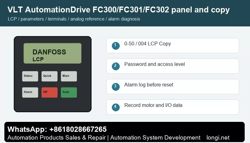
The graphical LCP provides Status, Quick Menu, Main Menu, Alarm Log, Hand On, Off, Auto On and Reset keys. The numerical LCP is useful for basic operation, but it is not the best choice for storing and transferring a complete parameter set.
Use the status display first to check frequency, current, reference, direction, terminal state and alarm number. Use the quick menu for motor data, acceleration/deceleration and basic limits. Use the main menu for I/O, analog scaling, protection, bus communication and advanced functions.
Use parameter 0-50 LCP Copy. Press Off first, enter 0-50 from Main Menu, select all parameters to LCP for backup, then move the LCP to a compatible drive and select all parameters from LCP. If the new drive has a different rating or software level, use the rating-independent option where applicable and verify motor, brake, encoder and safety-related settings.
Parameter copying is useful for replacement drives and repeat machines. Before copying, record motor nameplate data, start source, reference source, terminal functions, relay functions, brake settings, communication address and alarm action. If the new drive rating is different, do not copy all parameters blindly.
Access Restriction and Password Recovery
Use 0-60 Main Menu Password, 0-61 Access to Main Menu without Password and 0-65 Quick Menu Password. To prevent field changes, set a non-zero password and change 0-61 to read-only or no access. To unlock, enter the valid password and restore full access.
In service work, divide access into three levels: operators may start, stop, reset and view status; maintenance staff may read alarm logs and terminal states; commissioning engineers may edit motor, I/O, reference, communication and protection parameters. If a drive is locked, try the valid password first. If initialization is unavoidable, back up or photograph all available data before restoring defaults.
External Forward/Reverse Terminal Control
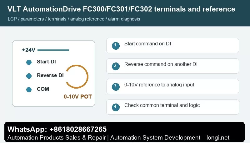
Terminals 12/13 provide +24 V and terminal 20 is common. Terminal 18 with parameter 5-10 is commonly used for start. Terminal 19 with parameter 5-11 can be used for reverse. Terminal 27 with parameter 5-12 is often used as coast stop inverse logic or no function. If terminal 27 remains configured as an interlock, jumper +24 V to terminal 27 or the drive may remain in coast/interlock state.
Use one digital input for start and another for reverse direction. Confirm +24 V, common terminal and input logic with a meter before connecting PLC outputs, switches or relays. After wiring, watch the terminal state on the LCP before running the motor. Test at low speed first, especially on pumps, fans, conveyors and spindle applications.
External Potentiometer Speed Reference
Terminal 50 provides +10 V, terminal 53 is the analog voltage input and terminal 55 is analog common. Wire the potentiometer ends to 50 and 55, and the wiper to 53. Set parameter 3-15 to analog input 53, 6-10 to 0 V, 6-11 to 10 V, 6-14 to the low reference and 6-15 to the high reference.
A potentiometer reference only works correctly when the hardware input type, reference source, low/high scaling and frequency limits match. Measure the analog input at minimum and maximum position. If the drive reports wire break or the speed is nonlinear, check common wiring, shield grounding, voltage/current selection and low/high scaling before replacing the control board.
Fault Codes and Troubleshooting
- Alarm 2, Live Zero Error: terminal 53/54 signal is below the scaled value. Check potentiometer wiring, shield, A53/A54 voltage/current switch and parameters 6-10 to 6-15.
- Alarm 4, Mains Phase Loss: check input fuses, contactor, terminal tightening and three-phase voltage balance.
- Alarm 7/8, DC Link Overvoltage/Undervoltage: overvoltage is often caused by too short deceleration or brake resistor issues; undervoltage requires checking supply capacity and dips.
- Alarm 9/10, Inverter or Motor Overload: verify motor nameplate parameters 1-20, 1-22, 1-23, 1-24 and 1-25, then inspect the mechanical load.
- Alarm 13/14/16, Overcurrent, Earth Fault or Short Circuit: disconnect motor leads, test insulation, and inspect U/V/W wiring, contactors and output reactors.
- Alarm 17/34, Control Word Timeout or Bus Fault: check fieldbus address, baud rate, shield grounding and command source.
- Alarm 30/31/32, Motor Phase Missing: inspect motor cable, output terminals, contactor and motor winding continuity.
- Alarm 38/47, Internal Fault or 24 V Supply Fault: power-cycle and remove external shorted loads first; repeated trips require board repair.
When troubleshooting, record the alarm number, frequency, current and DC link voltage at the moment of trip. If the drive runs without load but trips with load, focus on mechanical load, ramp time and motor data. If it trips without a motor, check output stage, brake circuit, internal supply and control board.
Field Checklist
- Before power-on: input voltage, grounding, motor insulation, brake resistor and cooling path.
- After power-on: panel status, terminal state, alarm log and access level.
- Before running: motor nameplate, command source, reference source, speed limits and ramps.
- Terminal control: test start, reverse, reset and interlock one by one.
- Analog reference: measure the actual signal and then set low/high scaling.
- Before delivery: save a parameter backup and document modified parameters and password policy.
Conclusion
The correct way to use the VLT AutomationDrive FC300/FC301/FC302 manual is simple: use the panel to confirm status, parameter copy for backup and recovery, access restriction to prevent wrong edits, digital inputs for command logic, analog scaling for speed range, and alarm logs for troubleshooting direction.