
I. Fault Definition and Engineering Background
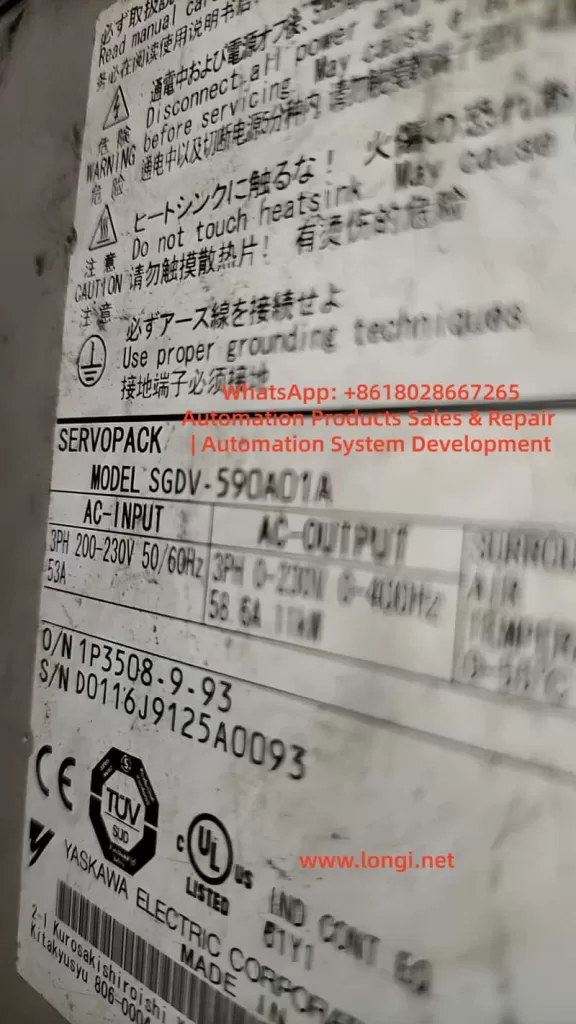
In the Yaskawa Σ-5 series servo system (SERVOPACK, with a typical model like SGDV-590A01A), the alarm code A.410 indicates:
The DC bus voltage in the main circuit is below the allowable threshold (Undervoltage Fault).
This alarm does not simply imply a low input voltage. Instead, the drive detects internally that:
- The DC bus voltage after rectification is insufficient.
- Or the bus voltage drops abnormally during operation.
According to the definition in the Σ-5 series manual, this alarm is usually triggered under the following conditions:
- For an AC200V system: The bus voltage is below approximately DC170V.
- For an AC400V system: The bus voltage is below approximately DC340V.
This means:
The essence of A.410 is an “energy chain break” problem, not a single-point voltage issue.
II. Main Circuit Structure and Fault Logic of SGDV
To fully understand A.410, it is essential to first understand the main circuit topology of SGDV:
Three-phase AC input
↓
Diode bridge (rectifier)
↓
Pre-charge resistor
↓
Pre-charge relay (bypass relay)
↓
DC bus capacitor (bulk capacitor)
↓
IGBT inverter module
Core detection points:
The drive continuously monitors the voltage of the DC BUS (P+ / N-).
III. Three Major Root Causes of A.410 Triggering
1️⃣ External Power Supply Anomalies (System-Level Issues)
Typical causes:
- Three-phase phase loss
- Low input voltage (< 180V)
- Excessive impedance in the power supply line
- Poor contact of contactors
Characteristics:
- The alarm occurs immediately upon power-up.
- All drives may be abnormal simultaneously.
2️⃣ Instantaneous Voltage Drops (Dynamic Issues)
Typical causes:
- Simultaneous startup of large-load equipment
- Grid fluctuations
- Abnormal braking energy feedback
Characteristics:
- Occurs occasionally during operation.
- Recovers after resetting.
3️⃣ Internal Faults in the Drive (Focus of Maintenance)
This is the part that maintenance personnel must focus on:
Key fault points:
| Part | Failure Mode |
|---|---|
| Diode bridge | Open-circuit/short-circuit of diodes |
| Pre-charge resistor | Open-circuit |
| Pre-charge relay | Failure to engage |
| DC bus capacitor | Reduced capacitance/increased ESR |
| Voltage detection circuit | Abnormal voltage division |
IV. Engineering-Level Diagnostic Process (Standard Steps)
Step 1: Input Power Confirmation
Measure:
- L1-L2
- L2-L3
- L1-L3
Standard:
- For a 200V system: 200 – 230V
- Phase-to-phase deviation < 5%
Judgment logic:
- ❌ If any phase is missing → External problem.
- ❌ If the voltage is low → Power supply problem.
Step 2: DC Bus Voltage Measurement (Core Step)
Measurement point:
- P+ and N-
Normal values:
| Input Voltage | DC Bus Voltage |
|---|---|
| 200V AC | 280 – 320V DC |
Result judgment:
| Measured Value | Conclusion |
|---|---|
| Normal | Rule out main circuit issues. |
| Significantly low | Internal fault. |
| No voltage | Rectifier/pre-charge problem. |
Step 3: Pre-charge Process Analysis
Normal process:
Power-up → Current-limited charging through resistor → Bus voltage rises → Relay engages (bypass resistor).
Abnormal manifestations:
- No “relay engagement sound”.
- Bus voltage does not rise.
Direct conclusion:
Pre-charge circuit fault.
Step 4: Dynamic Operation Detection
Observe:
- Whether there is a power drop during startup.
- Whether the alarm occurs during acceleration.
If the alarm only occurs during operation:
Focus on checking the bus capacitor and grid stability.
V. In-Depth Maintenance-Level Analysis
1️⃣ Diode Bridge Fault
Manifestations:
- Low DC bus voltage.
- Large voltage fluctuations.
Detection method:
Use a multimeter in diode mode to test in six directions.
Check for single-phase rectification.
2️⃣ Pre-charge Circuit Fault (Most Common)
Components:
- Pre-charge resistor
- Relay
- Control drive circuit
Fault manifestations:
- Bus voltage stalls at a low value (e.g., 100 – 200V).
- No relay engagement sound.
Judgment technique:
Observe the voltage change curve during power-up.
3️⃣ DC Bus Capacitor Degradation
Manifestations:
- Normal startup.
- Voltage drop during operation.
Causes:
- Increased ESR.
- Reduced capacitance.
Detection method:
Test with an ESR meter.
Observe the ripple voltage.
4️⃣ Voltage Detection Circuit Anomaly
Components:
- Voltage-dividing resistors
- Operational amplifier
- ADC input
Manifestations:
- The actual voltage is normal, but the alarm is triggered.
Action required:
Compare the actual measured value with the drive’s displayed value.
VI. Typical Case Studies (Practical Examples)
Case 1: A.410 Alarm Immediately upon Power-up
- Normal input.
- DC bus voltage is only 120V.
Conclusion:
The pre-charge relay did not engage.
Case 2: Occasional A.410 Alarm during Operation
- Normal startup.
- Alarm during acceleration.
Conclusion:
High ESR of the capacitor.
Case 3: Alarm after Replacing the Power Supply
Conclusion:
Input phase sequence or voltage mismatch.
VII. Quick Location Techniques (On-Site Practical)
Technique 1: Listen to the Relay
- “Click” sound → Normal.
- No sound → Pre-charge problem.
Technique 2: Observe the Bus Voltage Curve
- Smooth rise → Normal.
- Stagnation → Pre-charge resistor problem.
- Sudden drop → Capacitor problem.
Technique 3: Compare Multiple Devices
- Alarms occur simultaneously → Power supply problem.
- Alarm on a single device → Internal problem.
VIII. Maintenance Recommendations and Replacement Strategies
Priority of must-replace components:
- Pre-charge relay
- Electrolytic capacitor
- Diode bridge
Do not blindly replace:
- Control board
- CPU module
Unless it is confirmed that there is an anomaly in the detection circuit.
IX. Preventive Measures (Engineering Level)
Power Supply Side:
- Use a voltage stabilizer.
- Avoid long-distance power supply.
Equipment Side:
- Regularly replace capacitors (every 5 – 7 years).
- Check contactors.
System Design:
- Add bus monitoring.
- Reasonably configure braking units.
X. Summary
A.410 is not simply a “low voltage” alarm but a comprehensive manifestation of anomalies in the servo system’s energy supply chain.
From a maintenance perspective, the core of diagnosis lies in:
- Determining whether it is an external or internal problem.
- Focusing on the DC bus voltage as the key variable.
- Prioritizing the troubleshooting of the pre-charge circuit.
In actual maintenance:
- Over 80% of A.410 faults are caused by pre-charge or bus issues.
- Mastering the system structure and voltage change patterns is more crucial than simply checking the alarm code.