
Introduction
The Xintian NSD-A/P series frequency converter is a high-performance, low-voltage, multi-functional device suitable for industrial applications ranging from 0.4 kW to 560 kW. This series supports vector control and V/F control, and is equipped with advanced PLC function interfaces and various communication protocols, such as RS485/Modbus. It is an ideal choice for modern industrial equipment. This document provides a detailed introduction to the operation panel functions, parameter settings, external control, and troubleshooting methods to help users safely and efficiently utilize the equipment.
Part 1: Introduction to Operation Panel Functions
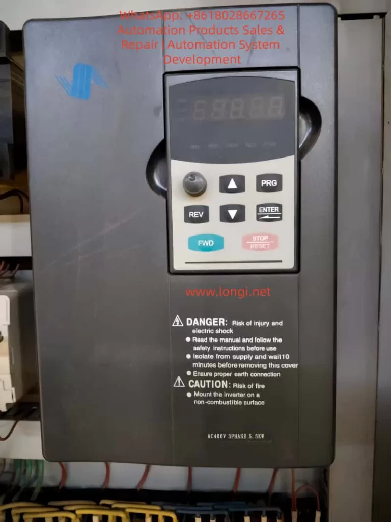
Basic Structure of the Operation Panel
- LED Display: Shows output frequency, current, voltage, or fault codes. For example, in running mode, it defaults to displaying the current frequency, such as “50.00” indicating 50 Hz.
- Status Indicators: Include DRV, FREF, FOUT, IOUT, FWD, REV, etc., used for quickly determining the status of the frequency converter.
Key Functions
- PRG (Program Key): Enters the parameter setting mode. Press and hold to return to the previous menu.
- ENTER (Confirm Key): Confirms selections or saves parameter modifications.
- UP/DOWN (Up/Down Keys): Increases or decreases parameter values and scrolls through menus.
- FWD/REV (Forward/Reverse Keys): Initiates forward or reverse operation.
- STOP/RESET (Stop/Reset Key): Stops operation or resets faults.
Parameter Initialization
- Ensure the frequency converter is stopped, then press the PRG key to enter the parameter setting mode.
- Navigate to F0.02 (Initialize Parameters), set it to 1, and press ENTER to confirm.
- The frequency converter will flash “INIT” as a prompt. Initialization is complete when it automatically resets.
Password Setting and Removal
- Setting a Password: Enter F0.00, set a 4-digit password, and press ENTER to save.
- Removing a Password: Enter the correct password to unlock, then set F0.00 to 0 and press ENTER to save.
Parameter Access Restrictions
- Enter F0.01 and set the access level (0 for full access, 1 for basic parameters, 2 for advanced parameters).
- Press ENTER to save.
Part 2: External Terminal Forward/Reverse Control and External Potentiometer Speed Adjustment
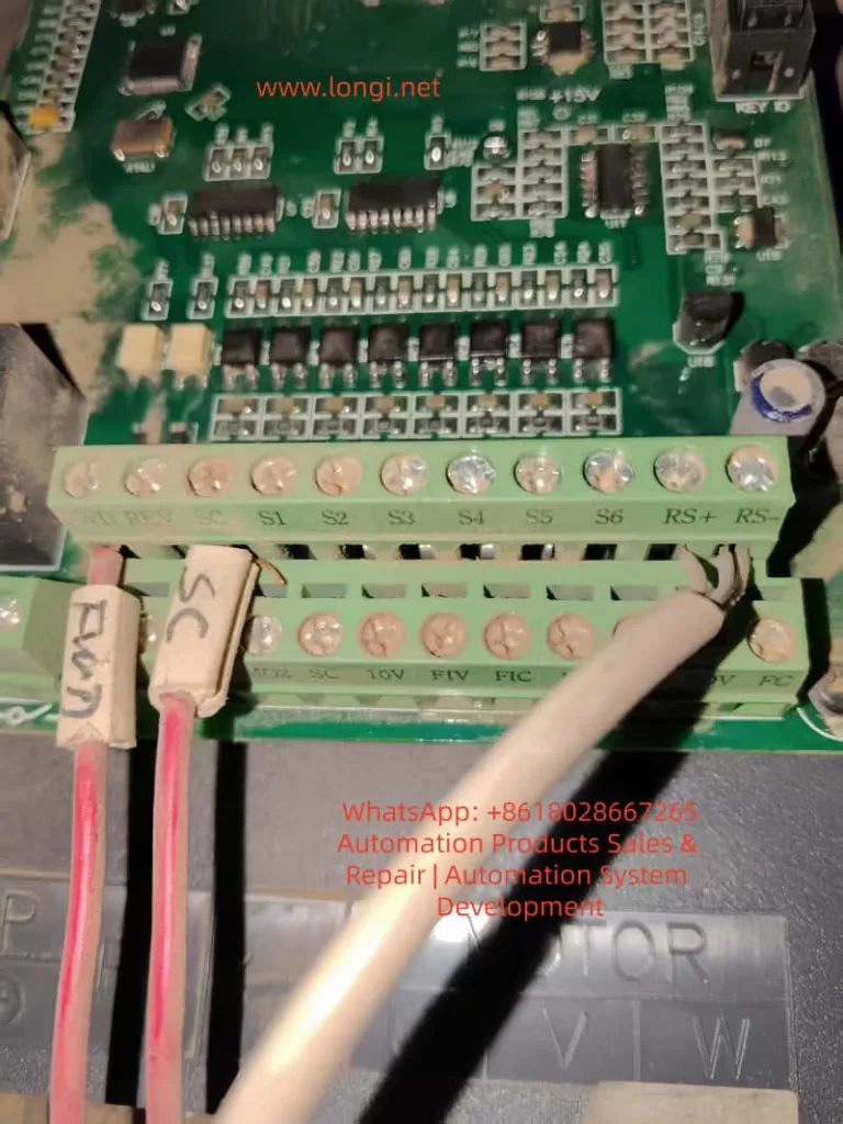
External Terminal Forward/Reverse Control
- Wiring: Connect the FWD terminal to one end of a switch, and the other end of the switch to COM. Connect the REV terminal to one end of another switch, and the other end of that switch to COM.
- Parameter Settings:
- Set F2.00 to 1 (External Terminal Control).
- Set F2.01 to 1 (Two-Wire Control Mode 1).
- Power-On Test: Close the FWD switch for forward motor rotation, and close the REV switch for reverse motor rotation.
External Potentiometer Speed Adjustment
- Wiring: Connect one end of the potentiometer to +10V, the middle tap to AI1, and the other end to GND.
- Parameter Settings:
- Set F0.01 to 2 (Analog AI1 Speed Adjustment).
- Set F0.02 to 0.10s (Analog Input Filtering).
- Set F0.03 and F0.04 to the minimum and maximum frequencies, respectively.
- Operation: Rotate the potentiometer while powered on to adjust the frequency.
Part 3: Frequency Converter Fault Codes and Solutions
Common Fault Codes and Solutions
| Fault Code | Description | Possible Causes | Solutions |
|---|---|---|---|
| E.01 | Overcurrent | Overloaded, too short acceleration time | Extend acceleration time, check motor insulation |
| E.02 | Overvoltage | Too short deceleration time, brake resistor failure | Extend deceleration time, install brake resistor |
| E.03 | Undervoltage | Low grid voltage, loose power lines | Check input voltage, tighten connections |
| E.04 | Overheating | Fan failure, high ambient temperature | Clean fan, reduce ambient temperature |
| E.05 | Motor Overload | Load exceeds rated value, incorrect parameter settings | Adjust motor protection parameters, reduce load |
| E.06 | PID Fault | PID feedback signal lost | Check PID parameters, inspect sensor wiring |
| E.07 | Communication Fault | Loose RS485 wires | Check RS485 connections, confirm Modbus parameters |
| E.08 | External Fault | External terminal input signal | Check S1-S6 terminals, clear external signal sources |
| E.09 | Internal Fault | Control board issue | Reset; if ineffective, contact the manufacturer for repair |
| E.10 | EEPROM Fault | Parameter storage error | Initialize parameters, back up data and reset |
General Fault Resolution Process
- When a fault occurs, the panel displays the fault code, and the motor stops.
- Press STOP/RESET to reset. If ineffective, power off for 5 minutes and try again.
- Check the fault history and determine the cause based on the code.
- Adjust parameters or inspect hardware, then test operation.
Conclusion
The Xintian NSD-A/P series frequency converter, with its powerful features and user-friendly design, is an excellent choice for industrial control. Through this guide, users can master the operation panel, parameter management, external control, and fault diagnosis. In practical applications, optimize parameters according to site conditions, such as using PID in pump systems to achieve constant pressure water supply, saving over 30% in energy. This manual emphasizes safety first; read all warnings before operating. For more advanced applications, such as Modbus communication or multi-speed settings, refer to the parameter table for expansion.