Introduction
In modern industrial automation, servo drives play a crucial role. Acting as the bridge between motors and control systems, they must not only provide stable power and driving capability but also precisely process real-time signals from feedback devices. If the feedback system fails, the drive cannot initialize or operate correctly, leading to fault alarms and machine downtime.
This article focuses on Error Code Er.25 in Parker TWIN-N series servo drives, analyzing its definition, root causes, troubleshooting methods, and preventive measures. It also presents real case studies and maintenance guidelines, offering engineers and technicians a comprehensive reference to handle this error effectively.
1. Overview of Parker TWIN-N Series Servo Drives
Parker Hannifin is a globally recognized provider of motion and control technologies. Its TWIN-N series servo drives are widely applied in packaging machines, textile equipment, electronic manufacturing, and other high-precision industrial automation fields.
Key features of the TWIN-N series include:
- Dual-axis design: One drive can simultaneously control two brushless motors, saving space and cost.
- Multiple feedback compatibility: Supports Resolver, Incremental Encoder, SinCos, EnDat, and Hiperface.
- Flexible parameter configuration: Different motor and feedback types can be adapted via parameter settings.
- Advanced control functions: Provides position control, speed control, torque control, electronic cam, and other functions.
Among these functions, the correct initialization of feedback signals is critical. When the drive cannot establish a valid speed loop feedback, it triggers the Er.25 alarm.
2. Official Definition of Er.25
According to the Parker TWIN-N / SPD-N user manual:
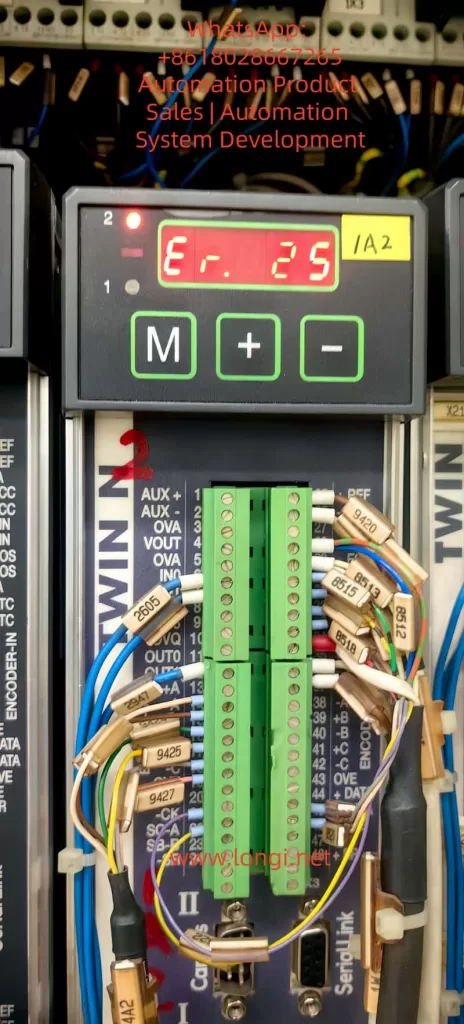
Er.25 – Speed loop FBK initialization error
Recommended actions:
- Check speed feedback (Speed FBK) parameter settings.
- Check speed feedback (Speed FBK) connections.
This indicates that during startup, the drive fails to initialize the feedback required for the speed loop. Essentially, the drive cannot obtain valid speed feedback from the encoder or resolver, preventing the closed-loop control system from functioning.
3. Possible Causes of Er.25
Based on the manual and practical field experience, the following are the most likely causes of Er.25:
3.1 Incorrect feedback type configuration
The drive supports different feedback devices, and each requires correct parameter configuration:
- Resolver mode for resolver feedback.
- Incremental encoder mode with proper pulse number and supply voltage.
- EnDat or Hiperface modes with specific communication protocols.
If the configuration does not match the actual feedback hardware, the initialization fails.
3.2 Wiring and connection issues
Feedback wiring typically includes power supply, signal lines, and shielding. Problems such as:
- No voltage or reversed polarity on +5V / +8V power.
- Broken, shorted, or swapped A/B/Z channels.
- Incorrect Sin+/Sin− / Cos+/Cos− wiring.
- Improper grounding of shield cables.
These can all cause the initialization error.
3.3 Faulty feedback device
Internal damage to the feedback device may lead to errors:
- Open winding in resolver.
- Malfunctioning photodiode in optical encoders.
- EEPROM failure in EnDat/Hiperface devices.
3.4 Electromagnetic interference (EMI) and environment
Industrial sites often have strong EMI sources such as welding machines, large inverters, or solenoids. Poor shielding or excessive cable length may cause unstable signals at startup, leading to Er.25.
3.5 Drive hardware or firmware issues
If the feedback input board is defective or the firmware has bugs, the drive may also fail to initialize. Though less common, this should be considered after external causes are ruled out.
4. Step-by-Step Troubleshooting
A structured troubleshooting process ensures efficient diagnosis and resolution:
Step 1 – Verify feedback type configuration
- Check drive parameter (e.g., Pr196) to confirm correct selection of Resolver, Incremental, or SinCos feedback.
- Compare motor nameplate and encoder type with drive configuration.
Step 2 – Verify feedback power supply
- Measure encoder supply voltage (+5V or +8V) with a multimeter.
- Confirm stable supply, correct polarity, and no short circuits.
Step 3 – Inspect wiring and signals
- Use an oscilloscope to check A/B/Z or Sin/Cos waveforms.
- Ensure signal symmetry, integrity, and no significant noise.
- Confirm secure wiring and proper shield grounding.
Step 4 – Perform encoder phasing (alignment)
- Execute encoder phasing procedure if using incremental or SinCos encoders.
- For EnDat/Hiperface, re-download EEPROM data if required.
Step 5 – Cross-test with a spare feedback device
- Replace with a known good encoder/resolver to rule out sensor damage.
Step 6 – Check drive hardware
- If external checks are normal, suspect damage to feedback interface or firmware issues. Contact the manufacturer or service center for repair.
5. Case Study
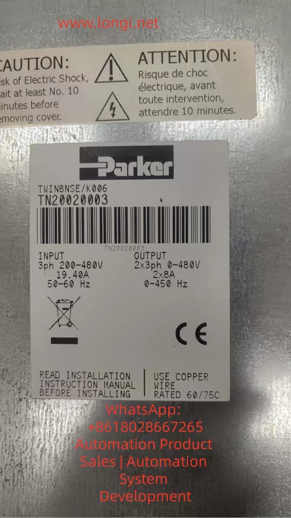
In a production line, a Parker TWIN8NSE K006 drive repeatedly showed Er.25 during startup. Investigation revealed:
- The motor used an incremental encoder, but the drive remained configured in Resolver mode.
- The encoder supply voltage was correct, but no pulses were detected at the signal terminals.
Solution:
- Corrected the feedback type parameter to “Incremental Encoder.”
- Re-wired the feedback cable and performed encoder phasing.
- Restarted the drive, and the error disappeared.
This case highlights the importance of both parameter configuration and wiring inspection.
6. Preventive Measures
To minimize recurrence of Er.25, the following preventive practices are recommended:
6.1 Proper cabling
- Use twisted, shielded cables for feedback signals.
- Avoid routing feedback lines parallel to power cables.
- Keep cable length within the specified range (typically 20–35 m).
6.2 Routine inspection
- Check encoder waveforms every six months.
- Clean connectors regularly to prevent dust or oil contamination.
6.3 Parameter management
- After replacing or resetting the drive, always reconfigure feedback parameters.
- Ensure firmware version supports the chosen feedback protocol.
6.4 Parameter backup
- Save drive parameters in normal operation for quick restoration after faults.
6.5 EMI control
- Keep drives away from strong EMI sources.
- Use isolation transformers or EMI filters when necessary.
7. Conclusion
Error Code Er.25 in Parker TWIN-N series servo drives is a speed loop feedback initialization error. It is most commonly caused by incorrect feedback configuration, wiring problems, or faulty encoders. By applying a systematic troubleshooting approach—checking parameters, verifying wiring, confirming power, and testing feedback devices—engineers can quickly resolve the issue.
From a broader perspective, the feedback system acts as the “sensory organ” of the servo drive. Any malfunction, however minor, can disrupt the entire closed-loop system. Understanding the logic behind fault codes, combined with preventive maintenance practices, is essential for ensuring the long-term stability and reliability of servo drive systems.