
Danfoss iC2-Move User Manual Guide: Panel Status, Terminal Control, Analog Speed Reference and Fault Troubleshooting
Use the Manual as a Commissioning Map
For Danfoss iC2-Move, the manual should not be used as a random parameter dictionary. A practical commissioning sequence is to understand the LCP panel, confirm command source, confirm reference source, check digital input logic, scale the analog input, then read the alarm log. This order prevents many unnecessary board replacements.
The most important rule is: back up before changing parameters, identify the active command source before editing inputs, and check interlocks before suspecting hardware. Many field failures are caused by a missing common terminal, wrong analog input type, open external interlock, or conflict between local and remote control.
LCP Panel and Parameter Copying
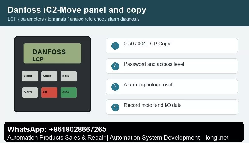
iC2-Move is a compact drive platform. Its indicators show running, warning and fault states, and the parameter menu is used for motor data, command source, reference source, input/output assignment and fault reset behavior.
Use the status display first to check frequency, current, reference, direction, terminal state and alarm number. Use the quick menu for motor data, acceleration/deceleration and basic limits. Use the main menu for I/O, analog scaling, protection, bus communication and advanced functions.
For iC2-Move, the practical replacement method is to export or record motor data, command source, reference source, ramps, protections and communication settings before power-down. If an external commissioning tool is used, save the active parameter set before replacing the drive.
Parameter copying is useful for replacement drives and repeat machines. Before copying, record motor nameplate data, start source, reference source, terminal functions, relay functions, brake settings, communication address and alarm action. If the new drive rating is different, do not copy all parameters blindly.
Access Restriction and Password Recovery
Access restriction should match responsibility. Operators should view status and reset ordinary faults; motor data, torque limits, braking, I/O functions and communication settings should remain under maintenance password control.
In service work, divide access into three levels: operators may start, stop, reset and view status; maintenance staff may read alarm logs and terminal states; commissioning engineers may edit motor, I/O, reference, communication and protection parameters. If a drive is locked, try the valid password first. If initialization is unavoidable, back up or photograph all available data before restoring defaults.
External Forward/Reverse Terminal Control
The manual identifies events such as external interlock 60, control word timeout 17 and 24 V supply fault 47. Confirm +24 V, common terminal, digital input number and input logic before assigning start, reverse, reset or external interlock to a DI terminal.
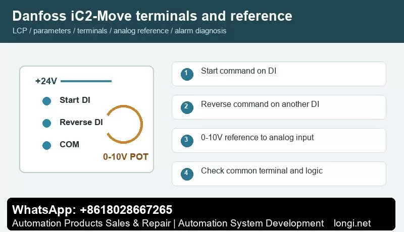
Use one digital input for start and another for reverse direction. Confirm +24 V, common terminal and input logic with a meter before connecting PLC outputs, switches or relays. After wiring, watch the terminal state on the LCP before running the motor. Test at low speed first, especially on pumps, fans, conveyors and spindle applications.
External Potentiometer Speed Reference
Analog reference is commonly assigned to terminal 33 or 34. Wire break fault 2 indicates that terminal 33/34 signal is below 50% of the configured value. Wire a potentiometer as +10 V, AI and COM, and match the low/high scaling to 0-10 V or 4-20 mA.
A potentiometer reference only works correctly when the hardware input type, reference source, low/high scaling and frequency limits match. Measure the analog input at minimum and maximum position. If the drive reports wire break or the speed is nonlinear, check common wiring, shield grounding, voltage/current selection and low/high scaling before replacing the control board.
Fault Codes and Troubleshooting
- Fault 2, Wire Break: analog signal on terminal 33/34 is below the low-limit value. Check signal source, common terminal, shield and input type.
- Fault 12/13, Torque Limit or Overcurrent: check ramp time, mechanical blockage, motor rating and torque limit parameters P5.10.1/P5.10.2.
- Fault 14/16/30/31/32, Earth Fault, Short Circuit or Phase Missing: focus on motor, cable and output contactor.
- Fault 17, Control Word Timeout: the fieldbus master or controller stopped sending control words.
- Fault 36/47, Mains Failure or 24 V Fault: inspect supply dips, terminal shorts and external sensor load.
- Fault 50/53/54/58/75, AMA Events: re-enter nameplate data and run tuning unloaded.
- Fault 59/60/69/80, Current Limit, External Interlock, Power Card Temperature or Initialization: handle load, interlock, cooling and parameter recovery respectively.
When troubleshooting, record the alarm number, frequency, current and DC link voltage at the moment of trip. If the drive runs without load but trips with load, focus on mechanical load, ramp time and motor data. If it trips without a motor, check output stage, brake circuit, internal supply and control board.
Field Checklist
- Before power-on: input voltage, grounding, motor insulation, brake resistor and cooling path.
- After power-on: panel status, terminal state, alarm log and access level.
- Before running: motor nameplate, command source, reference source, speed limits and ramps.
- Terminal control: test start, reverse, reset and interlock one by one.
- Analog reference: measure the actual signal and then set low/high scaling.
- Before delivery: save a parameter backup and document modified parameters and password policy.
Conclusion
The correct way to use the Danfoss iC2-Move manual is simple: use the panel to confirm status, parameter copy for backup and recovery, access restriction to prevent wrong edits, digital inputs for command logic, analog scaling for speed range, and alarm logs for troubleshooting direction.