
The Danfoss VLT2900 is an older but still widely used compact AC drive. It appears in fans, pumps, conveyors, textile machines, packaging equipment, dyeing machines and many other small-power industrial systems. Its parameter structure is close to the VLT2800 family, so many operation, wiring and fault-diagnosis methods are shared. For service work, the key is not to read the whole manual line by line, but to quickly master the practical workflow: use the panel correctly, copy parameters, unlock data changes, wire forward/reverse terminals, use a 0-10V potentiometer as a speed reference, and interpret Err.xx fault codes.
This guide summarizes the user manual from a repair and commissioning perspective. Parameter numbers are based on the VLT2900/VLT2800 manual structure. Before commissioning, always verify the nameplate, motor data, control logic and machine safety circuit.
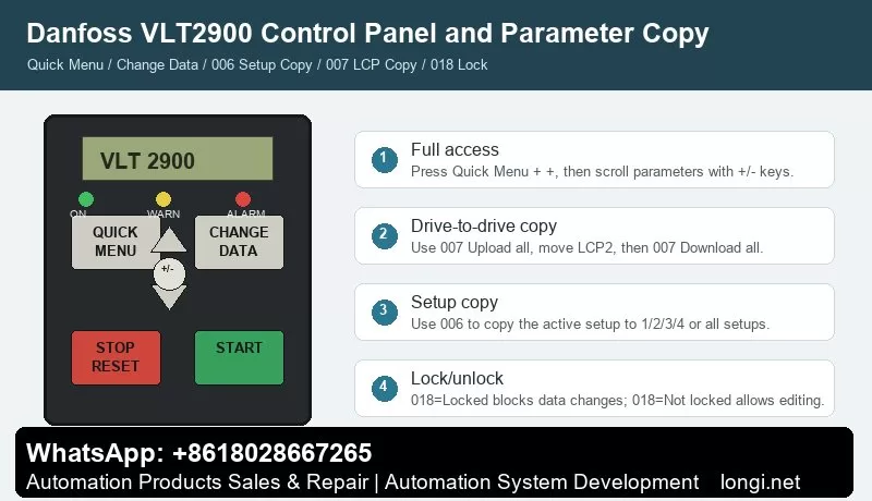
Control Panel and Menu Access
The basic VLT2900 panel normally includes QUICK MENU, CHANGE DATA, +, -, STOP/RESET and START. With an LCP2 control panel, extra keys such as OK, arrow keys, HAND, OFF, AUTO, FWD/REV and JOG may be available. The indicator LEDs show ON, WARNING and ALARM. A warning means an abnormal condition is present but the drive may continue to run; an alarm usually requires fault correction and reset.
QUICK MENU opens the quick commissioning menu. It normally contains motor nameplate data, minimum and maximum reference, ramp times and basic operation settings. Use + / – to scroll, press CHANGE DATA to edit, change the value with + / –, and confirm with CHANGE DATA or OK. Parameter values are stored automatically and remain after power loss.
If only a limited number of parameters are visible, the drive is usually not "encrypted". It is often still in Quick Menu mode. To access all parameters, press QUICK MENU and + at the same time to enter the full menu mode, then scroll to the required parameter.
STOP/RESET stops the drive command and resets alarms, but it is not a safety isolator. For short circuit, earth fault, overtemperature or power-stage faults, disconnect mains power and wait for the DC bus to discharge before touching the terminals.
Parameter Copying: 006 and 007 Are Different
Two parameters are commonly confused: 006 Setup copying and 007 LCP copy.
Parameter 006 Setup copying copies the active setup inside the same drive. It can copy the active setup to Setup 1, 2, 3, 4 or all setups. It is useful when several machine recipes are needed. Stop the motor before copying because changes copied to the active setup can affect drive operation immediately.
Parameter 007 LCP copy is used with the LCP2 panel to move parameters from one drive to another. The normal workflow is:
- Install the LCP2 on the source drive.
- Enter 007 LCP copy.
- Select Upload all parameters.
- Move the LCP2 to the target drive.
- Select Download all parameters.
- If the target drive has a different power size, use Download size-independent parameters instead.
Do not blindly download all parameters between drives of different voltage class, power size or hardware version. After copying, verify motor parameters 102-106, references 204/205, ramps 207/208, terminal parameters in group 300 and communication parameters in group 500.
Locking, Unlocking and "Password" Misunderstanding
VLT2900 does not normally use a password-style lock for routine parameter access. Two conditions are often mistaken for encryption.
The first is limited menu access. Press QUICK MENU + + to enter full menu mode.
The second is the real data-change lock: 018 Data change lock. Set it to Locked [1] to block parameter changes. Set it back to Not locked [0] to allow editing. If the drive shows Warning 99 Locked, check parameter 018. If editing is still impossible, stop the motor, remove active start signals and confirm whether an LCP2 panel is required for editing.
External Forward/Reverse Control by Terminals
The manual gives practical examples for digital input control. Typical factory assignments include 302 Digital input terminal 18 = Start, 303 terminal 19 = Reversing, and 304 terminal 27 = Reset and coast inverse.
A practical forward/reverse wiring scheme is:
Terminal 12 provides the digital control supply.
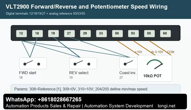
Terminal 18 receives the forward start signal. Wire a switch from 12 to 18 and set 302=Start [7].
Terminal 19 receives the reverse selection signal. Wire a switch from 12 to 19 and set 303=Reversing [10].
Terminal 27 is commonly used for coast stop inverse or reset/coast inverse. It normally needs a valid logic signal through the safety circuit. Set 304=Coasting stop inverted [2] or according to the actual machine requirement.
Also check parameter 200 Output frequency range/direction. If the drive is set for clockwise operation only, the reverse input will not produce reverse rotation. For real forward/reverse operation, select a direction range that allows both directions.
Test first at low frequency and without load. Confirm the output frequency, motor direction and mechanical safety before running the machine under load.
Potentiometer Speed Reference: Terminals 50, 53 and 55
The manual example for Potentiometer reference uses a voltage reference through terminal 53. The required settings are 308 Analog input = Reference [1], 309 Terminal 53 min scaling = 0V, and 310 Terminal 53 max scaling = 10V.
Typical 10k ohm potentiometer wiring:
Terminal 50: +10V supply to one end of the potentiometer.
Terminal 55: analog common to the other end.
Terminal 53: analog voltage input to the wiper.
Recommended parameters:
- 308 Terminal 53 analog input = Reference [1].
- 309 Terminal 53 min scaling = 0.0V.
- 310 Terminal 53 max scaling = 10.0V.
- 204 Minimum reference defines the minimum speed.
- 205 Maximum reference defines the maximum speed.
- 207/208 Ramp-up and ramp-down times should be set to match the mechanical inertia.
If the potentiometer does not work, measure the voltage on terminal 53 first. Then check parameter 308 and verify that the drive is in remote control and not being overridden by local reference, preset speed or serial communication. If Err.02 Live zero error appears, terminal 53 or 60 is below 50% of the configured minimum scaling value.
Fault Codes and Troubleshooting
VLT2900 alarms are displayed as Err.xx. A warning stays active while the condition exists. An alarm flashes until reset. A trip-locked fault requires power removal, fault correction and restart before reset.
Err.02 Live zero error: terminal 53 or 60 signal is below the expected minimum. Check potentiometer wiring, analog common, terminal 53 voltage, parameter 309/315 and sensor supply.
Err.04 Mains phase loss: check input fuses, contactor, terminals 91/92/93 and mains imbalance.
Err.05 Voltage warning high / Err.07 Overvoltage: usually caused by too short deceleration, high inertia, brake resistor faults or high mains voltage. Increase ramp-down time and inspect the brake circuit.
Err.06 Voltage warning low / Err.08 Undervoltage: check mains supply, contactor drop-out, rectifier, precharge circuit and DC bus capacitors.
Err.09 Inverter overload: check mechanical overload, drive sizing, acceleration time and cooling.
Err.10 Motor overloaded: verify motor parameters 102-106, load condition and cooling at low speed.
Err.11 Motor thermistor: check the PTC thermistor and wiring between a digital input and terminal 50, and verify parameter 128.
Err.12 Current limit: output current exceeds parameter 221. Check acceleration time, load, torque demand and mechanical friction.
Err.13 Overcurrent: check motor shaft blockage, motor cable, output short circuit and IGBT module. Do not keep resetting repeatedly.
Err.14 Earth fault: inspect motor insulation, motor cable, water ingress and shield contact. Disconnect power and test insulation.
Err.15 Switch mode fault: internal auxiliary power supply fault, usually a board-level repair issue.
Err.16 Short-circuit: check U/V/W phase-to-phase short circuit, motor winding and power module.
Err.17 Serial communication timeout: check group 500 communication parameters, address, baud rate, protocol and cable shielding.
Err.18 HPFB bus timeout / Err.34 HPFB communication fault: fieldbus or PROFIBUS option communication problem.
Err.33 Out of frequency range: check parameter 200, frequency limits and direction restrictions.
Err.35 Inrush fault: inspect precharge resistor, relay, rectifier and DC bus capacitors.
Err.36 Overtemperature: check fan, heatsink dust, ambient temperature, motor cable length, carrier frequency and mains voltage.
Err.37-45 Internal fault: internal control card, EEPROM, RAM, calibration, power card, software or I/O fault. Record the exact code before repair.
Err.50-56 AMT faults: automatic motor adaptation failed. Check motor nameplate data, output cable, motor phase connection and load condition.
Warning 99 Locked: parameter changes are locked. Check 018 Data change lock.
Practical Commissioning Sequence
Start by checking power wiring, motor insulation, earthing and control terminals. Enter full menu access, set motor data 102-106, configure terminal 18/19/27 logic, set reference limits 204/205, set ramps 207/208, configure terminal 53 with 308/309/310, then test the motor at low speed without load. After successful testing, back up parameters. Use 007 LCP copy for drive-to-drive copying and 006 Setup copying for internal setup duplication.
Conclusion
The VLT2900 manual becomes much easier to use when its main structure is clear: QUICK MENU is for fast commissioning, QUICK MENU + + gives full parameter access, CHANGE DATA edits values, STOP/RESET stops and resets, 006 copies internal setups, 007 copies parameters through LCP2, 018 locks or unlocks data changes, 302/303/304 define terminal 18/19/27 control, 308/309/310 define the 0-10V potentiometer reference, and Err.xx codes point the troubleshooting direction.
Used this way, the manual is not just a parameter list. It becomes a practical diagnostic map for commissioning, service and repair of Danfoss VLT2900 drives.