
Table of Contents
- Introduction
- Basic Principles and Structure of Servo Drives
- 2.1 Core Composition of Servo Systems
- 2.2 Technical Features of the SD700 Series Servo Drive
- 2.3 Operating Modes and Control Logic of Servo Drives
- Common Fault Types and Cause Analysis of Servo Drives
- 3.1 Fault Classification and Level Division
- 3.2 Cause Analysis of Er.022 (System and Checksum Error)
- 3.3 Comparison with Other Common Fault Codes (Er.001, Er.003, Er.016, etc.)
- Diagnosis and Handling Process for Er.022 Fault
- 4.1 Fault Phenomena and Preliminary Judgment
- 4.2 Principle and Operation Steps of Soft Reset (FN002)
- 4.3 Advanced Diagnosis: Parameter Verification and Hardware Inspection
- 4.4 Case Study: Actual Handling Process of Er.022
- Preventive Maintenance and Optimization of Servo Drives
- 5.1 Key Points for Regular Inspection and Maintenance
- 5.2 Parameter Backup and Recovery Strategies
- 5.3 Environment and Wiring Optimization
- 5.4 Firmware Upgrade and Compatibility Management
- Fault Prediction and Intelligent Development Trends of Servo Systems
- 6.1 Predictive Maintenance Based on Data Analysis
- 6.2 Application of Artificial Intelligence in Servo Fault Diagnosis
- 6.3 Intelligent Upgrade of Servo Systems in the Context of Industry 4.0
- Conclusion and Recommendations
1. Introduction
As the core execution unit of modern industrial automation systems, servo drives are widely used in CNC (Computer Numerical Control) machine tools, robots, packaging machinery, printing equipment, and other fields. Their high-precision and high-response control characteristics significantly improve production efficiency and product quality. However, due to complex working environments, electrical interference, and incorrect parameter settings, servo drive failures occur frequently. Among them, Er.022 (System and Checksum Error) is a relatively common fault in the SD700 series servo drives.
This article takes the SD700 Er.022 fault as the starting point to systematically analyze the causes, diagnostic methods, and handling processes of servo drive faults. It also discusses preventive maintenance and intelligent development trends, aiming to provide engineering and technical personnel with a scientific and efficient solution for fault handling and optimization.
2. Basic Principles and Structure of Servo Drives
2.1 Core Composition of Servo Systems
A servo system typically consists of the following three parts:
- Servo Drive: Receives control signals to drive the servo motor.
- Servo Motor: The actuator that converts electrical energy into mechanical motion.
- Feedback Device (Encoder): Detects the motor’s position and speed in real-time and feeds it back to the drive to form a closed-loop control.
Inside the servo drive, core components such as DSP (Digital Signal Processor), FPGA (Field-Programmable Gate Array), Power Module (IGBT), and Communication Interfaces are integrated to achieve precise control through high-speed computing.
2.2 Technical Features of the SD700 Series Servo Drive
The SD700 series is a high-performance servo drive with the following features:
- High-Speed Response: 3kHz speed loop response bandwidth, suitable for high-dynamic applications.
- Multiple Control Modes: Supports position control, speed control, torque control, and hybrid control.
- Rich Communication Interfaces: Supports industrial fieldbuses such as EtherCAT, Profinet, CANopen, and RS-485.
- Intelligent Adjustment Functions: Automatic inertia identification, robust control, bandwidth setting, etc.
- Fault Diagnosis and Protection: Built-in multiple fault codes and alarm mechanisms for quick problem localization.
2.3 Operating Modes and Control Logic of Servo Drives
The main operating modes of a servo drive include:
- Position Control Mode: Precisely controls the motor position via pulse signals.
- Speed Control Mode: Controls the motor speed via analog or digital signals.
- Torque Control Mode: Directly controls the motor’s output torque, suitable for applications like tension control.
The control logic is based on the PID (Proportional-Integral-Derivative) algorithm, combined with feedforward compensation and filtering processing to achieve high-precision closed-loop control.
3. Common Fault Types and Cause Analysis of Servo Drives
3.1 Fault Classification and Level Division
Servo drive faults can be divided into the following types:
- Hardware Faults:
- Power module damage (IGBT short circuit, open circuit).
- Encoder wire break or signal abnormality.
- Main circuit overvoltage/undervoltage.
- Software/Parameter Faults:
- Incorrect parameter settings (e.g., Pn000 control mode mismatch).
- Firmware abnormality or checksum failure (e.g., Er.022).
- Communication Faults:
- Fieldbus communication interruption (EtherCAT, CANopen, etc.).
- Command signal loss or interference.
- Environment and Wiring Faults:
- Electromagnetic Interference (EMI).
- Poor grounding or power fluctuation.
According to severity, faults can be divided into:
- Category 1 (Severe): Requires immediate shutdown (e.g., overcurrent, overvoltage).
- Category 2 (Warning): Operation can continue but requires attention (e.g., overheating).
- Category 3 (Information): Recorded in logs, does not affect operation (e.g., parameter changes).
3.2 Cause Analysis of Er.022 (System and Checksum Error)
Er.022 is usually triggered by the following reasons:
- Parameter Verification Failure:
- Parameter groups (e.g., Pn000~Pn999) are set out of range or have logical conflicts.
- Motor model parameters (e.g., Pn100, Pn101) do not match the actual hardware.
- Firmware or EEPROM Abnormality:
- Firmware upgrade interruption or data corruption.
- Aging of EEPROM storage chip leading to data loss.
- Encoder Initialization Failure:
- Encoder communication interruption (SD+, SD- signal abnormality).
- Insufficient battery voltage for absolute encoders (below 3.0V).
- Power or Grounding Issues:
- Control power supply (L1C, L2C) fluctuation.
- Signal interference caused by poor grounding.
3.3 Comparison with Other Common Fault Codes
| Fault Code | Description | Possible Causes |
|---|---|---|
| Er.001 | Overcurrent | Excessive load, IGBT damage, motor stall |
| Er.003 | Overvoltage | Excessive regenerative energy, braking resistor fault |
| Er.016 | Encoder Disconnected | Encoder cable disconnected, poor contact |
| Er.020 | Communication Timeout | Fieldbus communication interruption, address conflict |
| Er.022 | System and Checksum Error | Parameter error, firmware abnormality, encoder initialization failure |
4. Diagnosis and Handling Process for Er.022 Fault
4.1 Fault Phenomena and Preliminary Judgment
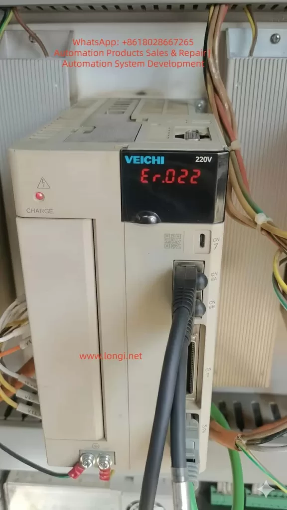
Typical phenomena of Er.022:
- The drive panel displays “Er.022”, and the servo motor stops.
- Cannot start via the Servo ON (/S-ON) signal.
- The alarm light (ALM) is constantly on.
Preliminary Judgment Steps:
- Check for recent parameter changes or firmware upgrades.
- Confirm if the encoder cables are connected properly (SD+, SD-, BAT+, BAT-).
- Check if the control power supply (L1C, L2C) is stable.
4.2 Principle and Operation Steps of Soft Reset (FN002)
Soft Reset is a standard operation to clear temporary fault states. It does not clear user parameters but reloads system defaults.
Operation Steps:
- Enter Fn Mode: Press the MODE/SET key to switch to the auxiliary function (Fn) mode.
- Select FN002: Use the ▲/▼ keys to select FN002 (Soft Reset).
- Execute Reset: Press the MODE/SET key to confirm; the drive will re-initialize.
- Observe Result:
- If the fault clears, normal operation resumes.
- If the fault persists, proceed to advanced diagnosis.
4.3 Advanced Diagnosis: Parameter Verification and Hardware Inspection
If the soft reset is ineffective, further diagnosis is required:
- Parameter Verification:
- Check if Pn000 (Control Mode) matches the actual application.
- Confirm if Pn100 (Motor Model) and Pn101 (Encoder Type) are correct.
- Use FN000 (Alarm Record) to view historical faults.
- Encoder Inspection:
- Measure if the encoder power supply (+5V, 0V) is normal.
- Check the absolute encoder battery voltage (should be ≥3.0V).
- Use an oscilloscope to detect if there is pulse output on SD+ and SD- signals.
- Hardware Inspection:
- Measure if the IGBT module is short-circuited (use a multimeter to measure resistance between U/V/W and ground).
- Check if the main circuit capacitors are bulging or leaking.
- Confirm if grounding is reliable (≤1Ω).
4.4 Case Study: Actual Handling Process of Er.022
Case Background:
A CNC machining center using an SD700-7R6A drive suddenly reported Er.022 and failed to start.
Troubleshooting Process:
- Soft Reset: Executed FN002, but the fault remained.
- Parameter Check: Found that Pn100 was mistakenly set to “0” (the default should be “7”).
- Parameter Correction: After restoring Pn100 to “7”, the fault was cleared.
- Root Cause Analysis: The parameter loss was caused by operator misoperation.
Conclusion:
- Er.022 is mostly caused by parameter errors or encoder abnormalities.
- Soft Reset is the first step; if ineffective, parameters and hardware need in-depth inspection.

5. Preventive Maintenance and Optimization of Servo Drives
5.1 Key Points for Regular Inspection and Maintenance
- Daily Inspection:
- Confirm no alarms on the drive panel.
- Check if the motor running sound is abnormal (e.g., noise, vibration).
- Weekly Inspection:
- Clean the drive cooling fan and filter.
- Check if wiring terminals are loose.
- Monthly Inspection:
- Measure the absolute encoder battery voltage.
- Check if the main circuit capacitors are bulging.
- Yearly Inspection:
- Use FN100 (Vibration Detection) to evaluate the mechanical state.
- Back up all parameters (Pn group).
5.2 Parameter Backup and Recovery Strategies
- Use host computer software to back up parameters regularly (e.g., SD700 supporting debugging software).
- Backup files should include:
- Pn parameters (control parameters).
- Fn auxiliary function settings.
- Internal position data (e.g., origin offset).
- When restoring, parameters should be loaded step-by-step to avoid conflicts caused by batch writing.
5.3 Environment and Wiring Optimization
- Electromagnetic Compatibility (EMC):
- Separate servo cables from signal cables by a distance of ≥30cm.
- Use shielded cables and ensure the shield layer is grounded at a single point.
- Power Quality:
- Use a regulated power supply to avoid voltage fluctuations exceeding ±10%.
- Install a noise filter at the main circuit input.
- Grounding Standards:
- Ensure common grounding for the drive, motor, and control cabinet, with grounding resistance ≤1Ω.
- Avoid ground loops (e.g., interference caused by multi-point grounding).
5.4 Firmware Upgrade and Compatibility Management
- Check the manufacturer’s official website regularly for the latest firmware.
- Back up parameters before upgrading and confirm compatibility with the motor model.
- Do not power off during the upgrade process to prevent EEPROM damage.
6. Fault Prediction and Intelligent Development Trends of Servo Systems
6.1 Predictive Maintenance Based on Data Analysis
Through IoT (Internet of Things) and big data analysis, real-time monitoring is performed on:
- Motor temperature, vibration, and current fluctuations.
- Drive alarm logs and parameter change trends.
- Using machine learning algorithms to predict faults (e.g., IGBT aging, encoder failure).
Case:
Brands like Siemens and Fanuc have launched cloud monitoring platforms that use AI to analyze historical data and warn of IGBT faults one month in advance.
6.2 Application of Artificial Intelligence in Servo Fault Diagnosis
- Automatic Fault Classification:
- Use NLP (Natural Language Processing) to parse alarm descriptions and automatically match solutions.
- Intelligent Parameter Optimization:
- AI dynamically adjusts PID parameters and gain settings based on load changes.
- Remote Expert Systems:
- Combined with AR (Augmented Reality), technicians can receive real-time guidance via smart glasses.
6.3 Intelligent Upgrade of Servo Systems in the Context of Industry 4.0
- Digital Twin:
- Build a virtual model of the servo system to simulate fault scenarios and optimize parameters.
- Edge Computing:
- Embed edge AI chips in the drive to process data in real-time and reduce cloud latency.
- Adaptive Control:
- The system automatically identifies load changes and switches control modes (e.g., from speed mode to torque mode).
7. Conclusion and Recommendations
7.1 Summary
- Er.022 faults are mostly caused by parameter errors, encoder abnormalities, or firmware corruption, and can be quickly recovered via Soft Reset (FN002).
- Preventive maintenance is the key to reducing faults; regular parameter backup, wiring checks, and environment optimization are essential.
- Future servo systems will develop towards intelligence and predictive maintenance, combining AI, IoT, and Digital Twins to improve reliability.
7.2 Recommendations
- For Engineers:
- Familiarize yourself with the drive manual and master the use of Fn auxiliary functions.
- Establish a parameter backup library to avoid data loss due to misoperation.
- For Enterprises:
- Invest in intelligent monitoring systems to implement predictive maintenance.
- Train employees regularly to improve fault diagnosis capabilities.
- For System Integrators:
- Consider EMC protection and grounding standards during the system design phase.
- Choose servo drive brands that support remote diagnosis.