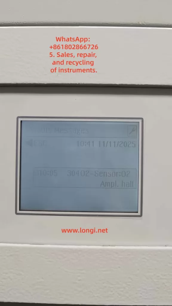
I. Problem Background and On-site Phenomena
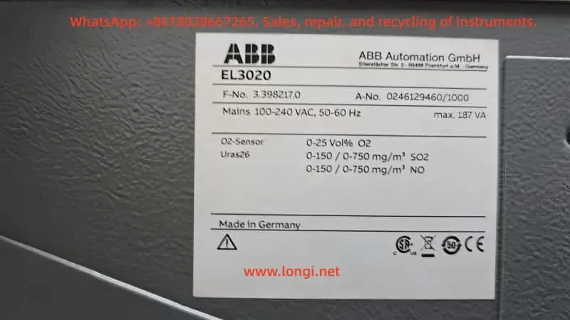
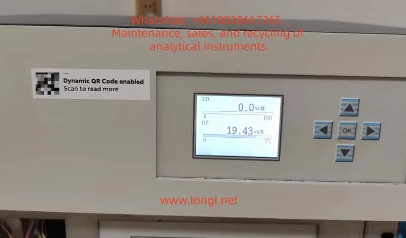
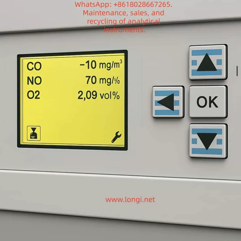
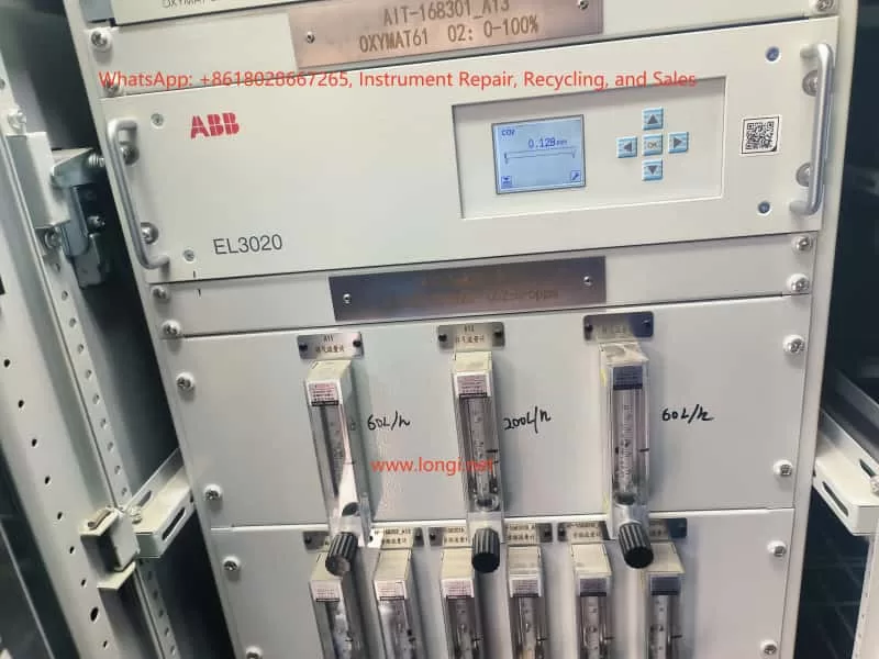
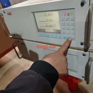
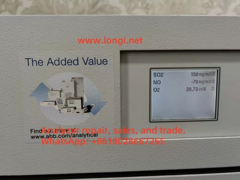
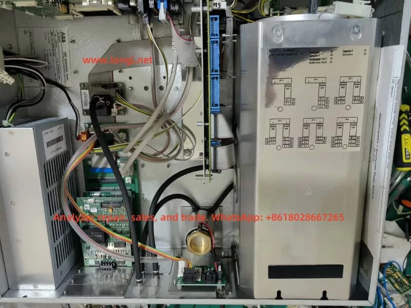
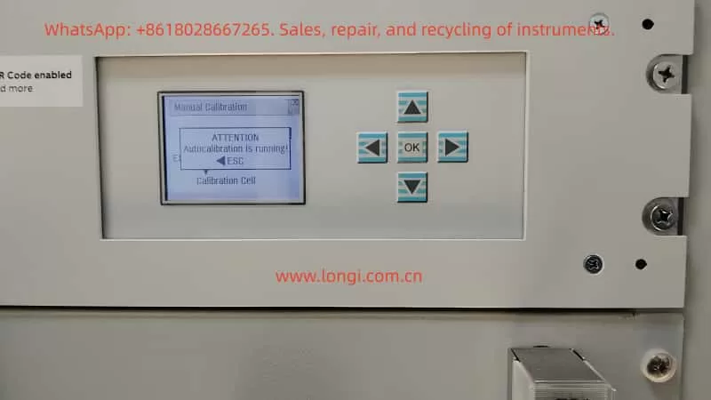
ABB EL3020 infrared gas analyzers are widely used in industrial flue gas analysis, process gas monitoring, and environmental online monitoring systems for the continuous measurement of gases such as CO, CO₂, SO₂, and NOx. They feature both automatic and manual calibration functions. During on-site operation and maintenance, it is common to encounter a situation where, despite having introduced zero gas and span calibration gas in preparation for manual calibration, when accessing the “Manual Calibration” menu, the instrument interface displays the message “ATTENTION: Autocalibration is running!”. At this point, the zero and span calibration menus cannot be accessed, and the buttons cannot be used to select calibration items. The instrument appears to be “stuck” on the calibration interface, leading customers to mistakenly assume it is a system crash, panel failure, or software anomaly. In reality, this is due to the normal operation of the EL3020’s internal calibration logic.
II. Overview of the EL3020 Calibration System
The EL3020 belongs to the ABB EasyLine/EL3000 series, and its calibration modes are divided into two categories: automatic calibration and manual calibration, with the system design following an exclusion principle.
1. Automatic Calibration
- Characteristics: It can be executed periodically at set times (e.g., once a day or once a week), triggered by external signals (such as from a PLC, digital input (DI), or Modbus), or initiated automatically after power-on. It automatically completes zero and span calibrations and controls the switching of calibration gases using solenoid valves.
- Purpose: To ensure the long-term stable operation of the analyzer without human intervention, preventing measurement errors caused by optical drift and environmental changes.
2. Manual Calibration
- Usage: It is used for initial installation and commissioning, after replacing components such as the optical module, for calibration gas comparison, post-repair calibration, and abnormal correction.
- Operation: It is carried out by engineers on-site and requires human confirmation of zero gas, span gas, and stabilization time, among other factors.
3. Exclusion Principle
During automatic calibration, the manual calibration function is forcibly locked by the system to prevent the simultaneous writing of calibration parameters by automatic and manual processes, interference with the calibration process by human actions, and measurement inaccuracies caused by parameter confusion.
III. Meaning of the “Autocalibration is running” Status
When the EL3020 displays “Autocalibration is running”, it does not necessarily mean that the device is actively switching solenoid valves to introduce calibration gases. Instead, it indicates that the system’s automatic calibration process is in an incomplete state, which may result from the following situations:
1. Automatic Calibration is Actually in Progress
For example, when the instrument has just been powered on, when it has reached the scheduled time for automatic calibration, or when an external PLC has just triggered a calibration signal. At this time, the instrument is undergoing processes such as gas circuit switching, sensor stabilization, zero-point collection, span collection, data calculation, and storage. Manual calibration is locked until these processes are completed.
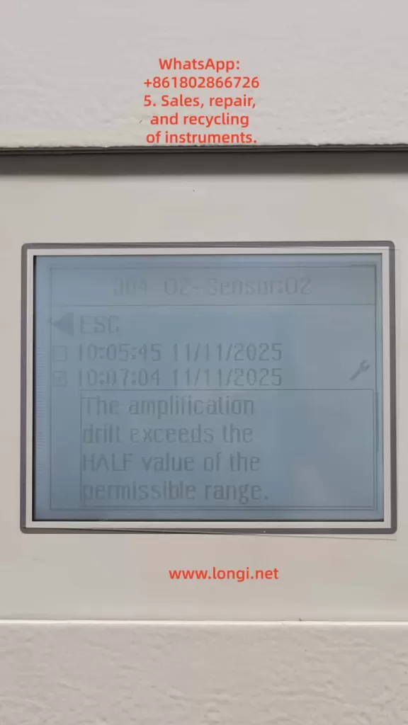
2. Automatic Calibration was Interrupted, and the Status was Not Reset (Most Common)
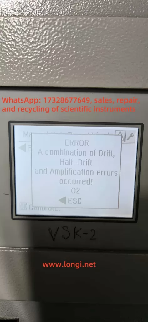
During the calibration process, sudden power outages, insufficient calibration gas pressure, gas circuit blockages or leaks, abnormal optical module signals, premature termination by operators, or abnormal external control signals can cause the automatic calibration process to be incomplete. As a result, the system’s “calibration status bit” remains in the “running” state, and the menu is locked.
3. The Preconditions for Automatic Calibration Are Not Met for an Extended Period
If the sensor signal remains unstable for a long time, the temperature or light intensity does not reach the stability threshold, the zero gas or span gas concentration is not within a reasonable range, or the flow rate is abnormal, the automatic calibration process will continue to wait for these conditions to be met, and the status will remain “running”.
IV. System Design Reasons
From the perspective of analyzer system safety, it is a reasonable design to lock manual calibration when automatic calibration is not completed. Writing parameters during automatic calibration while manual writing occurs can lead to EEPROM data conflicts. Forcing a span calibration before zero-point collection is completed can cause serious proportional errors. An incomplete automatic calibration indicates that the current parameters have unknown credibility. Forcibly opening the manual entry point can easily result in “the more adjustments, the more errors” situations. Therefore, the EL3020 adopts a “status lock” mechanism, and manual calibration will always be unavailable as long as the automatic calibration status is not cleared.
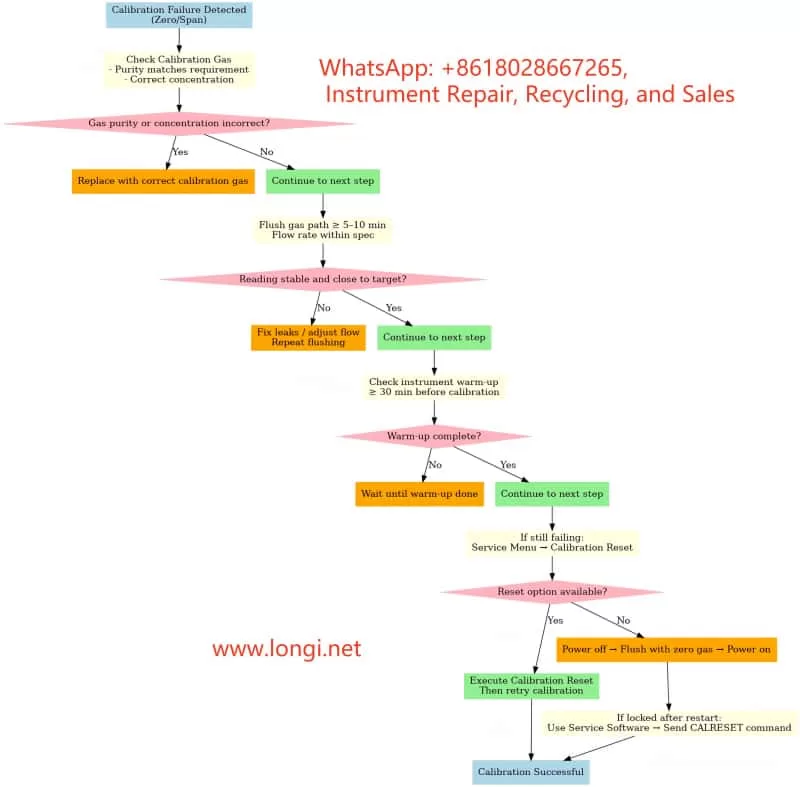
V. On-site Solutions
Engineering handling should follow the principle of “from software to hardware, from simple to complex”.
✅ Solution 1: Wait for the Automatic Calibration to Complete (Preferred)
When the device has just been powered on or an automatic calibration has just been triggered, ensure a normal supply of zero gas and span gas, and maintain stable flow, pressure, and temperature. Observe whether the status ends on its own. After the automatic calibration process is fully completed, the system will automatically release the manual calibration menu. This solution is suitable for newly commissioned instruments, normal periodic calibrations, and warm-up stages.
✅ Solution 2: Attempt to Abort the Automatic Calibration in the Menu
Some EL3000 series models support options such as “Abort Calibration” or “Stop Auto Calibration”. If such options are available in the menu, you can try to terminate the automatic process to make the system exit the “running” state. This solution is suitable for situations where the automatic calibration is obviously stuck, there is a history of human triggering, and you do not want to restart the device.
✅ Solution 3: Power Off and Restart (Most Common and Effective)
If the automatic calibration status cannot end on its own, stop the measurement, turn off the gas supply, and power off the instrument for at least 30 seconds. Then, power it back on, wait for the system to fully start up, and do not trigger the automatic calibration. Directly access the manual calibration menu. This solution is suitable for situations where the automatic calibration is abnormally interrupted, the menu is permanently locked, or the status is clearly abnormal.
✅ Solution 4: Eliminate the Root Cause of the Inability to Complete Automatic Calibration
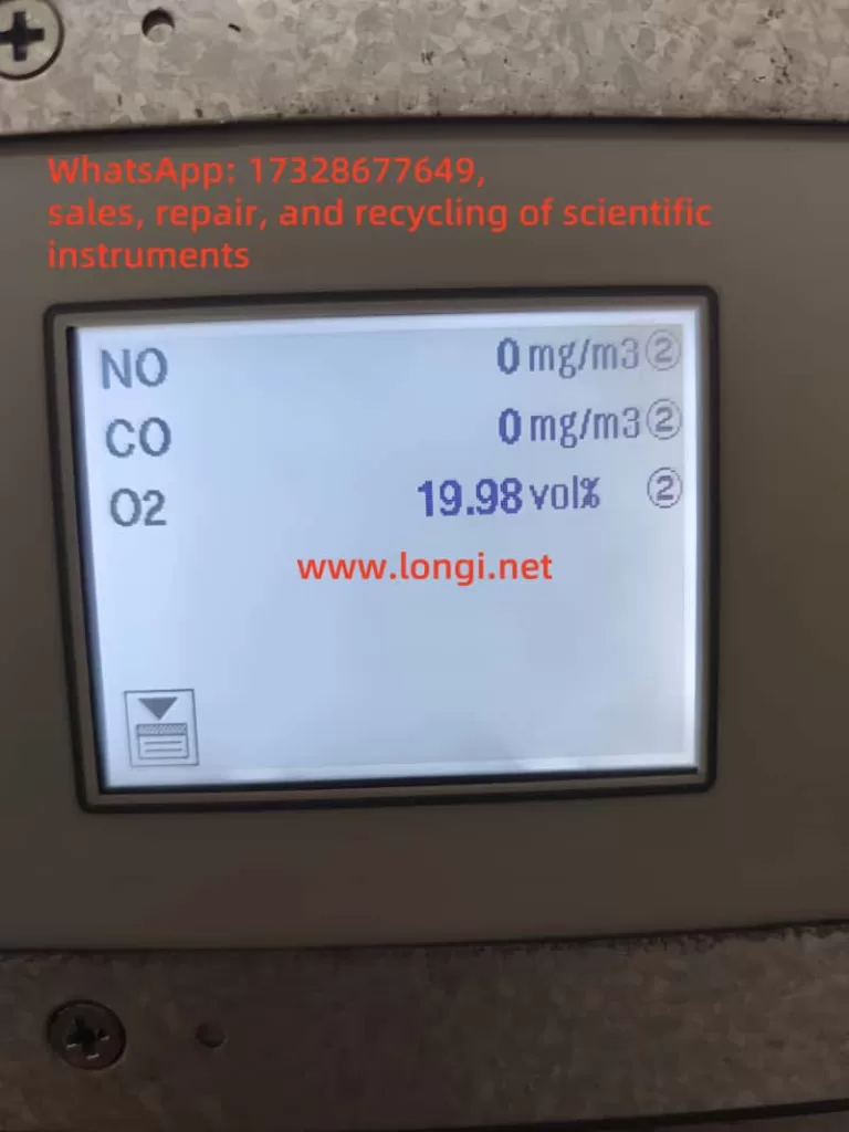
If the device repeatedly enters the “Autocalibration is running” state and cannot end, you need to investigate the root cause. Focus on checking whether the zero gas is truly zero, whether the span gas concentration is correct, whether the gas circuit is blocked, whether the solenoid valves are functioning, whether the flow rate is stable, whether the sensor signal is within a reasonable range, and whether there are external signals continuously triggering calibration. Otherwise, even after a restart, the device may enter automatic calibration again and get stuck.
VI. Engineering Experience Summary
In the EL3020 and the entire EL3000 series, the inability to enter manual calibration is almost never due to a broken panel and rarely a true software fault. In most cases, it is caused by the “automatic calibration status not being cleared”. The handling logic is not about “how to access it” but rather figuring out why the system believes that automatic calibration has not ended, why automatic calibration cannot be completed normally, and how to make the automatic process end correctly or be reset.
VII. Summary
Currently, the instrument is in the automatic calibration state. According to ABB’s design logic, the system will forcibly lock the manual zero and span calibration menus until the automatic calibration is completed. This is not a fault but a protection mechanism. You need to first allow the automatic calibration to complete or clear the automatic calibration status through a restart before performing manual calibration.
VIII. Conclusion
The “Autocalibration is running” message on the EL3020 reflects the instrument’s internal calibration status management mechanism. Correctly understanding it helps engineering personnel quickly determine the nature of the problem, avoid盲目 (blindly) disassembling the instrument or mistakenly assuming damage to the main board, improve on-site fault handling efficiency, and reduce the secondary risks caused by misoperations. The key to solving the problem lies in understanding “why the automatic calibration has not ended”.