Posted on

Practical Guide to ABB EL3020 Gas Analyzer: Negative CO Readings and Zero/Span Calibration

1. Introduction

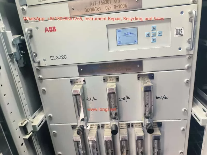
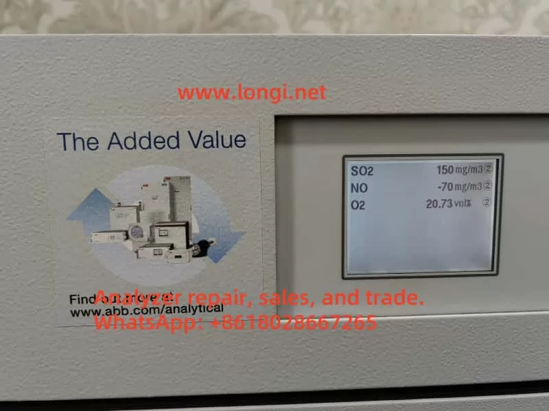
In industrial emission monitoring, combustion control, and process analysis, gas analyzers play a critical role in ensuring safety, efficiency, and compliance with environmental standards. The ABB EL3020 is a widely used multi-component gas analyzer based on infrared optical measurement principles. It is designed to continuously monitor gases such as CO, CO₂, NO, and SO₂ in various industrial applications.

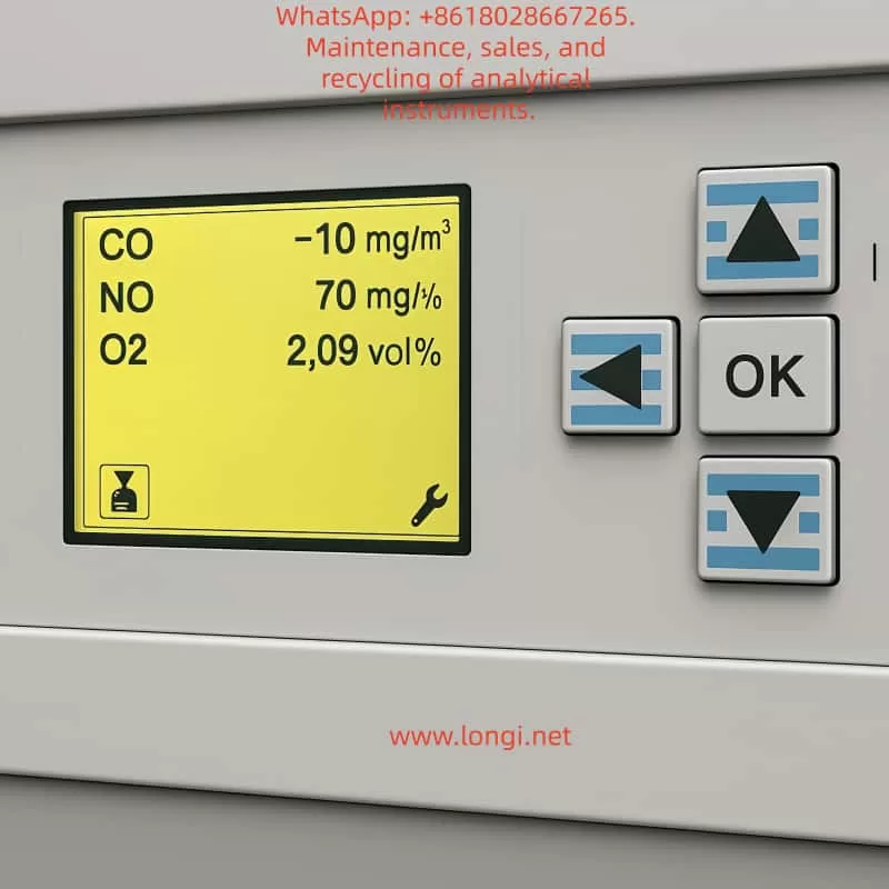
However, during long-term operation, users may sometimes encounter abnormal readings, the most common of which is negative CO concentration values. Such readings do not imply the physical existence of “negative carbon monoxide,” but instead reflect calibration drift, background interference, or hardware-related issues.

This article provides a detailed explanation of the EL3020’s measurement principle, analyzes the possible causes of negative CO readings, and presents practical zero calibration and span calibration procedures. The aim is to help engineers and operators quickly identify the root cause, restore measurement accuracy, and ensure stable operation of the analyzer.


EL3120

2. Operating Principle of ABB EL3020

2.1 Infrared Absorption Principle

The EL3020 operates on the principle of non-dispersive infrared absorption (NDIR).

  • Each gas molecule has a unique absorption band in the infrared spectrum.
  • When an infrared beam passes through a sample gas containing CO, the CO molecules absorb energy at specific wavelengths.
  • The detector measures the reduction in light intensity, which is directly proportional to the gas concentration.
  • By comparing the reference and measurement channels, the analyzer calculates the gas concentration.

2.2 Zero and Span Definitions

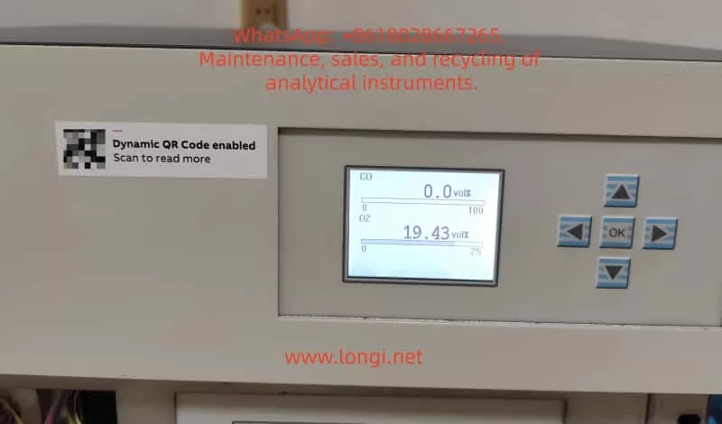
  • Zero Point: The output signal when no target gas is present (pure zero gas condition). Ideally, the instrument should display 0 ppm.
  • Span Point: The output when a known concentration of calibration gas is introduced. Span calibration adjusts the slope factor to ensure linear accuracy.

CO shows a negative value

3. Causes of Negative CO Readings

3.1 Zero Drift

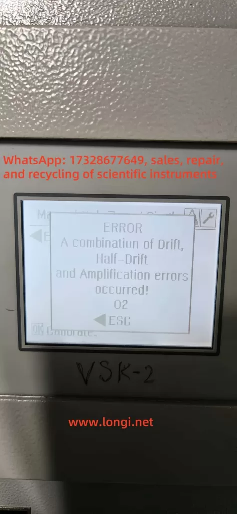
Over time, detector electronics and optical components may drift due to temperature variations and aging. If the zero point is not recalibrated, the baseline may shift below zero, producing negative values.

3.2 Background Interference

If the sampled gas contains almost no CO while the instrument’s baseline is incorrectly set too high, the computed result may fall below zero. Excess oxygen, water vapor, or other gases can also disturb the optical path.

3.3 Optical Contamination or Aging

Dust, condensation, or weakened infrared sources reduce the signal strength at the detector, leading to baseline shifts.

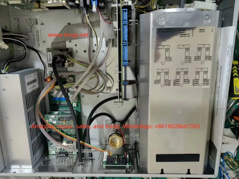
3.4 Hardware or Circuit Faults

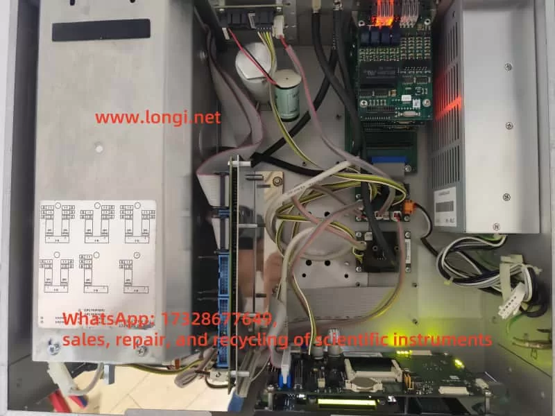
Faults in the analog acquisition board, A/D converters, or signal amplifiers can also cause abnormal negative readings. If only the CO channel is affected while NO and O₂ are stable, the issue likely lies in the CO detection unit.


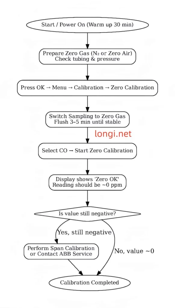
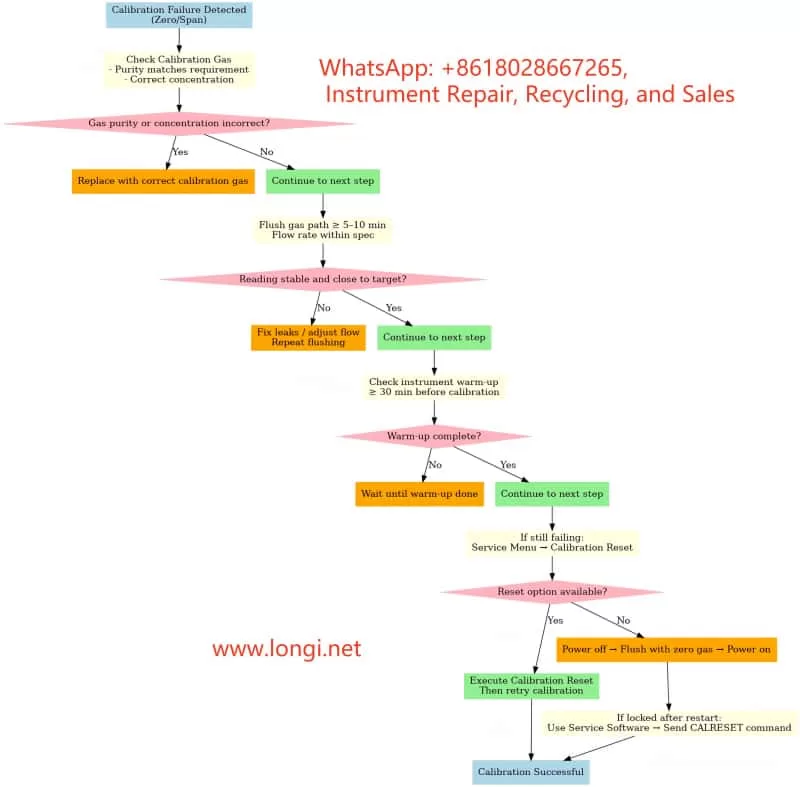
4. Zero Calibration Procedure

Zero calibration eliminates baseline drift and resets the analyzer output to zero under clean gas conditions.

4.1 Preparation

  1. Use high-purity nitrogen (99.999%) or certified zero air as the zero gas.
  2. Verify gas purity and set regulator output pressure to ~2 bar.
  3. Check sample lines for leakage or condensation.
  4. Power on the analyzer for at least 30 minutes to stabilize.

4.2 Step-by-Step Process

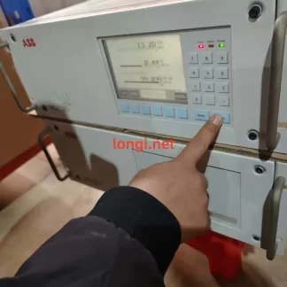
  1. On the panel, navigate: OK → Menu → Calibration → Zero Calibration.
  2. Select the CO channel.
  3. Switch the sample inlet to zero gas and flush for 3–5 minutes until stable.
  4. Execute Start Zero Calibration.
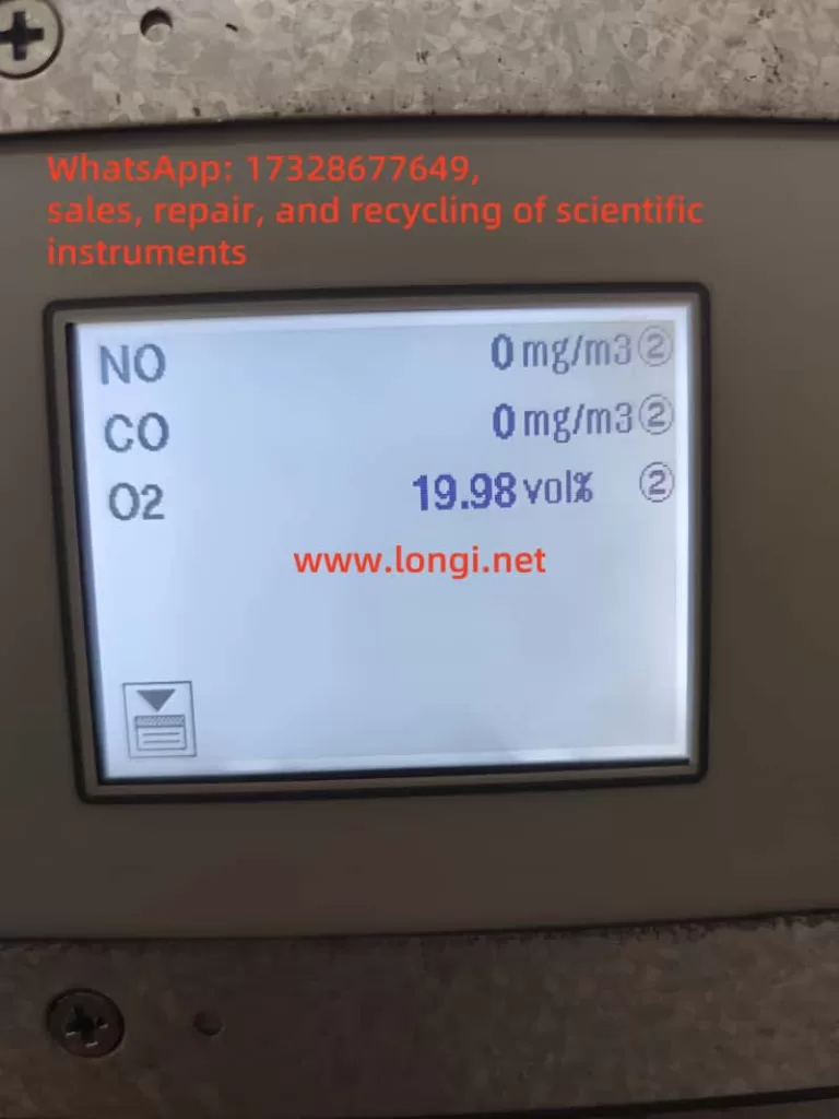
  5. After completion, the CO value should display close to 0 ppm (±2 ppm acceptable).

4.3 Evaluation

  • If “Zero OK” appears and the reading stabilizes, calibration is successful.
  • If negative values persist, further action such as span calibration or hardware inspection may be required.

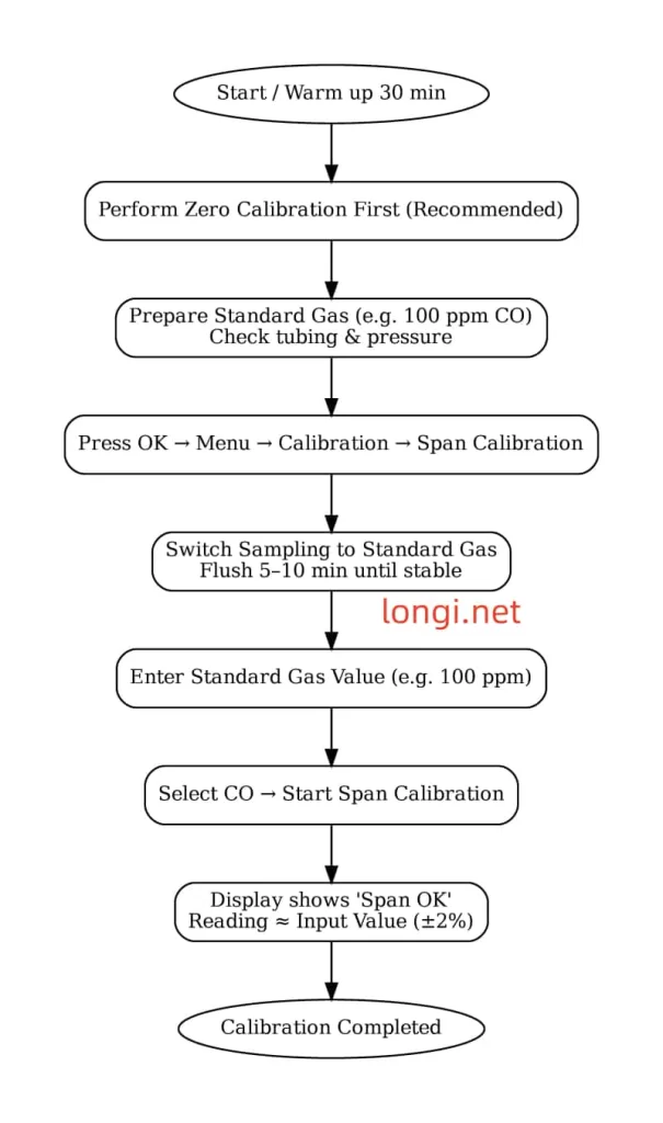
5. Span Calibration Procedure

Span calibration corrects the proportionality factor (slope) to align measured values with certified standard gas concentrations.

5.1 Preparation

  1. Use certified CO span gas, preferably at 60–90% of the measurement range (e.g., 100 ppm CO in N₂).
  2. Check cylinder, pressure regulator, and tubing for leaks.
  3. Perform zero calibration before span calibration for best results.

5.2 Step-by-Step Process

  1. On the panel, navigate: OK → Menu → Calibration → Span Calibration.
  2. Select the CO channel.
  3. Switch the sample inlet to the standard gas and flush for 5–10 minutes until stable.
  4. Enter the certified gas concentration (e.g., 100 ppm).
  5. Execute Start Span Calibration.
  6. The analyzer adjusts the slope factor and confirms with Span OK.

5.3 Evaluation

  • If the analyzer output matches the certified value (within ±2%), span calibration is successful.
  • Large deviations indicate optical degradation or electronic faults that may require service intervention.

6. Maintenance and Troubleshooting Recommendations

  1. Regular Calibration
    • Perform zero calibration monthly and span calibration every 1–3 months.
  2. Optical Cleaning
    • Inspect and clean optical windows and gas cells regularly. Prevent dust and moisture accumulation.
  3. Sample Line Maintenance
    • Avoid condensation and leaks in tubing. Use filters and dryers where necessary.
  4. Validation with Reference Gas
    • Periodically validate with independent standard gas to ensure accuracy.
  5. Hardware Inspection
    • If calibration fails, check the infrared source, detectors, and analog boards. Replace if necessary.

7. Case Study: Negative CO Reading Restored by Calibration

In a steel plant, operators observed the EL3020 CO channel consistently showing -5 ppm.

  1. Zero calibration with nitrogen reduced the offset, but the value remained at -3 ppm.
  2. A span calibration using 100 ppm CO gas showed the analyzer reading 95 ppm.
  3. After span adjustment, the zero point stabilized near 0 ppm and span response matched 100 ppm.

The issue was traced to slope drift in the CO channel, which was successfully corrected through calibration without requiring hardware replacement.


8. Conclusion

The ABB EL3020 is a reliable and accurate gas analyzer for continuous industrial monitoring. Negative CO readings are typically not measurement of “negative concentration” but symptoms of baseline drift or span factor deviation. Proper and regular zero calibration and span calibration are essential to maintain measurement accuracy.

For persistent negative values that cannot be corrected through calibration, optical contamination, component aging, or hardware malfunction should be considered. Timely maintenance and service support are key to ensuring the long-term stability of the analyzer.

By following standardized calibration procedures and maintenance practices, operators can keep the EL3020 functioning accurately and extend its service life in demanding industrial environments.


Posted on

ABB EL3020 (Uras26) CO₂ Analyzer: Calibration Principles, Common Failures, and On-site Troubleshooting

1. Introduction

The ABB EL3020 (equipped with the Uras26 infrared module) is a high-precision, multi-component gas analyzer widely used in chemical, metallurgy, power, and environmental sectors for continuous CO₂, CO, CH₄, and other gas measurements.
To ensure measurement accuracy and long-term stability, Zero Point Calibration and Span Calibration must be performed regularly. However, during field calibration, engineers often encounter “Calibration Rejected,” “Half Span Shift,” or complete lockout after a failed attempt, preventing further calibration and impacting operation.

This article explains the calibration principle, common causes of failure, error phenomena, troubleshooting steps, and recovery methods. It is based on real field cases, providing engineers with actionable, field-ready solutions.


2. Calibration Principles of the EL3020 (Uras26)

2.1 Zero Point Calibration

The purpose of zero point calibration is to eliminate background interference signals from the optical system and sensors when no target gas is present, aligning the measurement curve to zero.

  • Condition: Introduce zero gas without the target component (e.g., high-purity nitrogen or zero air).
  • Requirement: Gas purity must be adequate (CO₂ < 0.1 ppm for a 0–5 ppm range), the sampling path fully flushed, and readings stable.

2.2 Span Calibration

Span calibration adjusts the analyzer’s sensitivity near the full scale so that the measured value matches the standard gas concentration.

  • Condition: Introduce certified calibration gas with a known concentration (e.g., 3 ppm CO₂).
  • Requirement: Gas concentration must be accurate and stable, and match the value configured in the analyzer.

2.3 Calibration Protection Mechanism

To prevent operator errors from causing measurement drift:

  • If the current reading deviates too far from the expected zero/span value, the analyzer will display a “Span Shift” or “Half Span Error” warning.
  • In some firmware versions, a failed calibration triggers an automatic calibration lock, requiring reset/unlock before retrying.

3. Common Calibration Issues and Root Causes

3.1 “Half Span Error” Warning

Causes:

  1. Incorrect calibration gas concentration (zero gas contains CO₂ or span gas concentration mismatch).
  2. Residual sample gas in the line or insufficient flushing time.
  3. Abnormal flow rate (too low/high or unstable).
  4. Analyzer not stabilized (insufficient warm-up or optical drift).

Recommendations:

  • Verify calibration gas concentration and label match.
  • Flush for ≥5–10 minutes before calibration.
  • Adjust flow rate to recommended value (e.g., 60 L/h).
  • Warm up for ≥30 minutes before calibration.

3.2 Zero Calibration Rejection

Causes:

  • Current reading outside acceptable zero range (e.g., <0.1 ppm for a 0–5 ppm range).
  • Calibration lock active after a failed attempt.
  • Menu access restricted (requires service password).

Recommendations:

  1. Confirm zero gas purity (CO₂ < 0.1 ppm).
  2. Extend flushing until reading stabilizes.
  3. Check service menu for Calibration Reset option.
  4. If locked, perform unlock/reset before retrying.

3.3 Lockout After One Failed Calibration

Causes:

  • Firmware protection: Logs the failure and blocks further calibration until cleared.
  • Data integrity protection: Prevents repeated incorrect calibrations from accumulating drift.

Unlock Methods:

  • Menu Reset: Service → Calibration Reset.
  • Power cycle + Zero gas flush.
  • Factory Calibration Restore (use with caution – overwrites all current calibration data).
  • Serial Command Unlock via ABB EL3020 Service Tool (CALRESET command).

4. Field Troubleshooting and Operating Steps

4.1 Pre-Calibration Checklist

  1. Gas Verification
    • Confirm gas label matches instrument settings.
    • Use ≥99.999% high-purity nitrogen or equivalent zero gas.
  2. Flow and Gas Path
    • Check flowmeter reading matches recommended spec.
    • Inspect for leaks and verify valve positions.
  3. Warm-up and Stability
    • Warm up for 30–60 minutes.
    • Flush for 5–10 minutes after switching gases.

4.2 Calibration Execution

  1. Press the wrench icon on the right-hand side of the display to enter Maintenance Menu.
  2. Select Manual Calibration.
  3. Choose Zero Point or Span depending on the operation.
  4. Wait for the reading to stabilize before pressing OK.
  5. Verify reading changes after calibration completes.

4.3 After Calibration Failure

  1. Verify gas source → Flush → Retry.
  2. If still failing → Service Menu → Calibration Reset.
  3. If no reset option → Power cycle with zero gas flushing.
  4. If lock persists → Use service software via serial port to send CALRESET.

5. Case Study: CO₂ Zero Point Calibration Failure

Scenario:

  • Instrument: ABB EL3020 (0–5 ppm CO₂ range).
  • Zero gas: 99.999% high-purity nitrogen.
  • Flow rate: 60 L/h.
  • Issue: Zero point calibration triggers “Half Span Error,” lockout after failure.

Investigation:

  1. Gas purity verified.
  2. Found flushing time was only 2 minutes – insufficient for stability.
  3. Extended flushing to 10 minutes → Reading dropped from 0.35 ppm to 0.05 ppm.
  4. Performed Calibration Reset → Zero point calibration succeeded.

Takeaway:

  • Insufficient flushing time is a common cause.
  • First step after failure: reset/unlock before retry.

6. Button & Icon Functions

  • Left Icon (Envelope/File)
    Data logging and viewing functions. Opens historical records and calibration logs.
  • Right Icon (Wrench)
    Maintenance and calibration access: zero point, span calibration, gas path test, sensor status.

7. Preventive Maintenance Tips

  1. Regularly verify calibration gas purity to avoid contamination.
  2. Flush sampling lines thoroughly before calibration.
  3. Perform zero and span calibration according to manufacturer’s recommended cycle.
  4. Train operators to follow correct calibration procedures to minimize errors.

8. Conclusion

The ABB EL3020 (Uras26) offers stable, reliable high-precision gas analysis when paired with proper gas path management and calibration. Understanding the calibration principle, protection mechanism, and common failure modes enables operators to troubleshoot effectively and reduce downtime.
When calibration fails or lockout occurs, follow the outlined troubleshooting steps—starting from gas source and flow checks to warm-up, flushing, and finally reset/unlock procedures—to quickly restore normal operation.


Posted on

In-Depth Fault Analysis: Understanding “Drift + Half-Drift + Amplification” Combined Errors in ABB Continuous Gas Analyzers and How to Resolve Them

1. Overview and Error Description

During operation of ABB’s AO2000 series continuous gas analyzers (such as Fidas24, Magnos, etc.), the following error message may be displayed:

ERROR  
A combination of Drift,  
Half‑Drift and Amplification errors occurred!  
02 → ESC

This message indicates that the analyzer has simultaneously detected three types of offset-related faults: Drift, Half-Drift, and Amplification errors. When these faults are combined, the system flags a critical failure (error code 507/02), potentially halting analysis and rejecting calibration until the issue is resolved.


EL3020 ERROR

2. Explanation of Each Error

  • Drift Error: Occurs when the signal offset exceeds acceptable thresholds, indicating a deviation of the baseline from its expected value.
  • Half-Drift: Triggered when the drift exceeds 50% of the allowed range — considered a warning-level error.
  • Amplification Error: Involves abnormal gain changes where the signal is either over-amplified or under-amplified, making measurement inaccurate.

A combined error suggests the presence of multiple overlapping issues, usually triggering a safety lock to prevent invalid measurements or faulty gas composition reports.


3. Root Causes of Combined Error

To understand the fault comprehensively, we must examine it from the sensor behavior, calibration process, and environmental conditions:

a) Sensor Aging or Degradation

Infrared, paramagnetic, or thermal conductivity sensors may suffer from aging, leading to unstable offsets and signal gain. Optical sources, sample cells, and pre-amplifiers may degrade over time and trigger drift.

b) Environmental or Sampling Issues

Contaminated sampling lines (moisture, oil mist, or particulate matter) can distort calibration by affecting gas composition. Humidity and temperature fluctuations also contribute to drift and amplification failures.

c) Calibration Gas or Flow Irregularities

Inconsistent span or zero gas flow, or expired gas bottles, can lead to calibration errors. When calibration fails multiple times, the analyzer may flag this combined drift/amplification condition.


Normal display status of EL3020

4. Fault Classification and Corrective Actions

Fault TypeManifestationRecommended Action
Drift / Half-DriftBaseline deviation or slow measurement responseCheck drift logs and compare to tolerance
Amplification ErrorGain factor changes sharply from historical levelsEvaluate sensor electronics or pre-amp
Combined Error 507Calibration fails; analyzer halts measurementTrigger manual calibration and inspect logs
Environmental ImpactErrors repeat in humid/contaminated environmentsClean lines, dry filters, verify sample gas

5. Step-by-Step Troubleshooting Guide

Step 1: View Diagnostic Readings

Access the analyzer menu and retrieve drift, gain, and error logs. Compare with baseline values and specifications.

Step 2: Inspect and Clean Sampling System

  • Replace or clean sample tubing, filters, or water traps.
  • Verify that the calibration gas is flowing correctly and meets purity specifications.

Step 3: Perform Manual Calibration

Access maintenance mode and carry out a full zero/span calibration. If the system fails again:

  • Check whether the instrument is actually drawing calibration gas.
  • Monitor flowmeter readings and solenoid valve actuation.

Step 4: Component-Level Inspection

  • Replace sensors, detector modules, or signal pre-amplifiers if values are unstable.
  • Check power supply stability and internal electronics.
  • Reboot analyzer after hardware check.

Step 5: Validate with Monitoring

After repairs, allow the instrument to stabilize and log drift values over 24 hours. Ensure both zero and span values hold within specification.


6. Preventive Maintenance Recommendations

  1. Daily Drift Monitoring: Log drift rates at least once per shift.
  2. Monthly or Quarterly Calibration: Use certified calibration gas bottles with verified expiration dates.
  3. Gas Path Dryness: Keep the system moisture-free using desiccants or active dryers.
  4. Sensor Lifecycle Tracking: Monitor installation date and replace sensors per manufacturer’s suggested intervals.
  5. Firmware and Software Updates: Regularly update analyzer software to address known error conditions and optimize calibration routines.

Internal structure diagram of EL3020

7. Case Study Example

A gas analyzer running for 6+ months triggered a combined 507 error. Drift values reached 180%, amplification deviation was excessive, and span calibration repeatedly failed. After inspection, the calibration gas flow had dropped significantly, and condensation was found in the sampling line.

Corrective action included replacing the filter, drying the line, and restoring gas flow. After performing a fresh zero/span calibration, the analyzer resumed normal operation.

This case confirms that calibration integrity and sample system hygiene are crucial for reliable performance.


8. Conclusion

  • Fault nature: This combined error involves overlapping sensor baseline drift, amplification gain deviation, and calibration failure.
  • Resolution:
    1. Review diagnostic metrics.
    2. Clean sampling path.
    3. Recalibrate manually.
    4. Replace modules if needed.
    5. Reboot and test.
    6. Establish a preventive maintenance protocol.
    7. Log and trend drift data periodically.

By maintaining proper calibration procedures, monitoring drift trends, and proactively replacing aging components, operators can avoid 507/02 combined faults and ensure high availability and accuracy from ABB EL3020 or AO2000 gas analyzers.


Note: This article assumes the presence of standard modules such as Uras26, Magnos206, or Fidas24. Detailed troubleshooting should be tailored to your specific analyzer configuration and environmental conditions.


Posted on

User Guide for ABB EL3020 Continuous Gas Analyzer

Key Takeaways

  • Powerful Functionality: The ABB EL3020 is a high-precision continuous gas analyzer supporting multiple modules (e.g., Uras26, Magnos206) for industrial gas monitoring.
  • Wide Applications: Primarily used in non-hazardous environments for measuring flammable gases, suitable for industrial process control and environmental monitoring.
  • Operational Caution: Must be operated by qualified personnel, adhering to strict safety and installation requirements to prevent leaks or equipment damage.
  • Maintenance and Troubleshooting: Regular calibration and seal integrity checks are critical; fault codes provide clear diagnostics for timely resolution.
  • User-Friendly Design: Features an intuitive display interface and multiple connectivity options, supporting remote configuration and data logging.

This guide, based on the ABB EL3020 user manual, aims to assist users in understanding its features, usage, precautions, and maintenance procedures.


ABB EL3020

Features and Capabilities

The ABB EL3020 is a continuous gas analyzer designed for industrial applications, capable of accurately measuring the concentration of individual components in gases or vapors. Part of the ABB EasyLine series, it combines advanced technology with user-friendly design, making it suitable for various industrial settings.

Key Features

  • Versatile Analyzer Modules: Supports Uras26 (infrared), Magnos206 (oxygen), Caldos27 (thermal conductivity), Limas23 (ultraviolet), and ZO23 (zirconia) modules, enabling measurement of gases like CO, CO₂, CH₄, and O₂.
  • Robust Design: Housed in a 19-inch rack-mounted enclosure with IP20 protection, weighing 7-15 kg, ideal for indoor industrial environments.
  • Flexible Connectivity: Supports 100-240 V AC power, digital I/O, analog outputs, Modbus, Profibus, and Ethernet interfaces for seamless system integration and remote operation.
  • Calibration Options: Offers automatic and manual calibration using nitrogen, air, or span gases, configurable via the device or software (e.g., ECT).
  • Intuitive Interface: Displays gas component names, measured values, and units in measurement mode; menu mode provides configuration and maintenance functions with password protection and a 5-minute timeout.
  • Data Communication: Connects to computers via Ethernet using TCT-light and ECT software for configuration, calibration, and data logging, supporting Modbus TCP/IP protocol.

Applications and Usage Precautions

Applications

The ABB EL3020 is designed for measuring flammable gases in non-hazardous environments, with applications including:

  • Industrial Process Control: Monitors gas concentrations in production processes to ensure stability.
  • Environmental Monitoring: Measures industrial emissions to comply with regulatory standards.
  • Energy Sector: Used in power plants for gas analysis to enhance efficiency and safety.
  • Chemical Industry: Monitors gas components in chemical reactions to ensure safety and quality.

The device is suitable for indoor environments below 2000 meters altitude, with flammable gas concentrations not exceeding 15 vol.% CH₄ or C1 equivalents. It is not suitable for ignitable gas/air or gas/oxygen mixtures or corrosive gases without proper preprocessing.

Usage Precautions

To ensure safety and performance, adhere to the following precautions:

  • Personnel Requirements: Only qualified personnel familiar with similar equipment should operate or maintain the device.
  • Safety Compliance: Follow national electrical and gas-handling safety regulations, ensure proper grounding, and avoid using damaged or transport-stressed equipment.
  • Installation Environment: Install in a stable, well-ventilated location away from extreme temperatures, dust, and vibrations. For flammable gas measurements, ensure adequate air circulation (minimum 3 cm clearance), and if installed in a closed cabinet, provide at least one air change per hour.
  • Gas Handling: Use stainless steel or PTFE gas lines, avoid opening combustion gas paths, and regularly check seal integrity to prevent leaks that could cause fires or explosions. Limit combustion gas flow (e.g., max 10 l/h H₂ or 25 l/h H₂/He mixture) and install a shut-off valve in the gas supply line.
  • Environmental Protection: Protect the device from mechanical damage or UV radiation, especially the display window.
  • Usage Restrictions: The oxygen sensor and integrated gas feed option must not be used for flammable gas measurements.

ABB EL3020

Detailed Usage Steps and Methods

Preparation

Before installing the EL3020, ensure:

  • Thorough review of the manual to understand application and safety requirements.
  • Preparation of necessary materials, such as gas lines, fittings, and power cables.
  • Verification that the installation site meets environmental requirements (stable, ventilated, no extreme temperatures).

Unpacking and Installation

  • Unpacking: Due to the device’s weight (7-15 kg), two people are recommended for unpacking.
  • Gas Connections: Use PTFE sealing tape to connect sample, process, and test gas lines, ensuring a tight seal.
  • Installation: Secure the 19-inch enclosure in a cabinet or rack using appropriate mounting rails.

Connections

  • Gas Lines: Connect sample, process, and test gas lines, ensuring cleanliness and secure sealing. Install a micro-porous filter and flowmeter for protection if needed.
  • Electrical Connections: Connect power (100-240 V AC), digital I/O, analog outputs, and communication interfaces (Modbus, Profibus, Ethernet) as per the manual’s wiring diagrams.

Startup

  1. Power On: Connect and turn on the power supply.
  2. Purging: Purge the sample gas path with an inert gas (e.g., nitrogen) for at least 20 seconds (100 l/h) or 1 hour (200 l/h) to clear residual gases.
  3. Warm-Up: Allow 0.5-2 hours for warm-up, depending on the analyzer module.
  4. Introduce Sample Gas: After warm-up, introduce the sample gas.
  5. Configuration and Calibration: Verify configuration settings and perform calibration if necessary, using test gases (e.g., nitrogen) to adjust zero and span points.

Operation

  • Measurement Mode: The display shows gas component names, measured values, and units for routine monitoring.
  • Menu Mode: Access configuration, calibration, or maintenance functions via the menu, requiring a password. The system auto-exits after 5 minutes of inactivity.
  • Calibration Methods: Perform automatic calibration (using preset test gases) or manual calibration (via menu or ECT software to adjust setpoints).
  • Data Logging: Use TCT-light or ECT software via Ethernet for data recording, compliant with QAL3 requirements.
  • Remote Monitoring: Integrate with monitoring systems via Modbus TCP/IP protocol.

Routine Maintenance and Fault Code Meanings

Routine Maintenance

To ensure long-term performance, conduct regular maintenance:

  • Seal Integrity Checks: Use pressure tests or leak detectors to regularly verify the integrity of sample and combustion gas paths, ensuring a leak rate < 1×10⁻⁴ hPa l/s for combustion gas and < 2×10⁻⁴ hPa l/s for sample gas.
  • Calibration: Perform automatic or manual calibration as needed, using specific test gases (e.g., nitrogen) to adjust setpoints and ensure measurement accuracy.
  • Visual Inspection: Regularly check for wear, damage, or contamination, particularly in gas lines, fittings, and the display.
  • Software Updates: Periodically update ECT and other software to ensure compatibility and functionality.

Fault Codes

The EL3020 provides status messages (codes 110 to 803), categorized as follows:

  • A: Failure
  • W: Maintenance Request
  • F: Maintenance Mode
  • S: Overall Status

Common fault codes and their handling methods are listed below:

CodeCategoryMeaningHandling Method
110A S aInstrument is bootingNo action required, informational
122A S aIO module defectiveReplace IO module
250A S aAnalyzer not foundCheck connectors and cables
301A S aMeasured value exceeds A/D converter rangeCheck sample gas concentration and connectors, contact service if needed
322A S aFlame is outCheck gas supply and heater plug (for flame-based modules)
412F S aIgnition failedManually restart via menu, check process gases

Maintenance Procedures

  • Identify Fault: Access fault codes via the menu.
  • Troubleshooting: Follow the manual’s instructions for each fault code. For example:
    • Code 322 (Flame Out): Check combustion gas supply and heater plug.
    • Code 250 (Analyzer Not Found): Inspect cables and connectors.
  • Contact Service: If the issue persists, contact ABB Service; avoid attempting repairs beyond your qualifications.

Conclusion

The ABB EL3020 Continuous Gas Analyzer is a robust and versatile tool for industrial gas monitoring, offering high precision and flexibility across various applications. By following the usage steps, precautions, and maintenance procedures outlined in this guide, users can ensure safe operation and sustained performance. Regular calibration, seal integrity checks, and prompt resolution of fault codes are essential for maintaining measurement accuracy and safety.