Introduction
In the realm of industrial automation, the Variable Frequency Drive (VFD) stands as the heart of motor control systems, dictating the efficiency, precision, and reliability of production lines. Among the myriad of VFDs available in the market, the V600 Series manufactured by Shenzhen Kingda Electric Technology Co., Ltd. has carved a niche for itself due to its robust performance and cost-effectiveness. However, like all sophisticated power electronics, it is susceptible to specific failure modes. One of the most critical and frequently encountered alarms in this series is EC.21.
This alarm code signifies a Temperature Sensor Fault. While it may appear as a simple numeric code on the LED display, the implications are far-reaching. If misdiagnosed or ignored, an EC.21 fault can lead to catastrophic thermal runaway, IGBT module failure, and costly unplanned downtime. This article provides an exhaustive technical analysis of the EC.21 fault, dissecting its root causes, establishing a logical diagnostic workflow, and offering actionable solutions for engineers and maintenance personnel.
1. The Phenomenon: Understanding the Symptoms
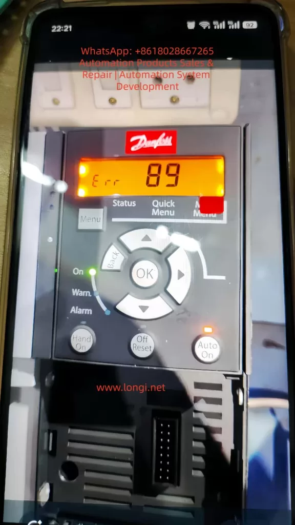
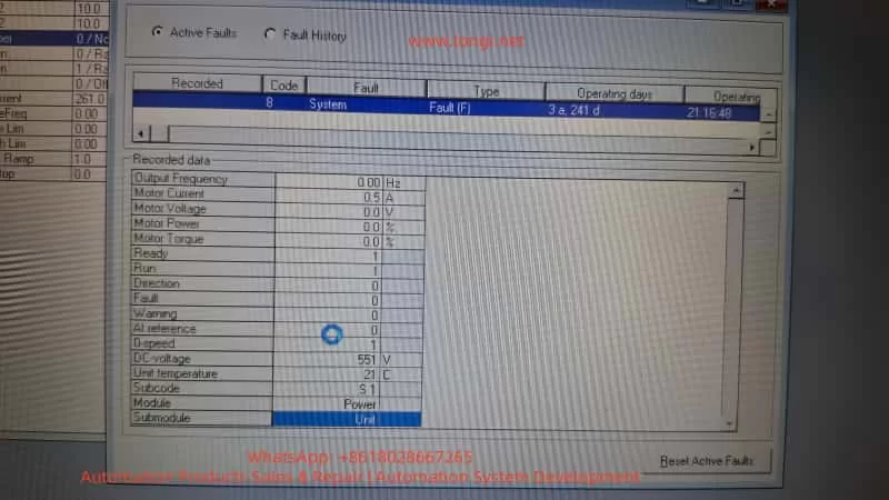
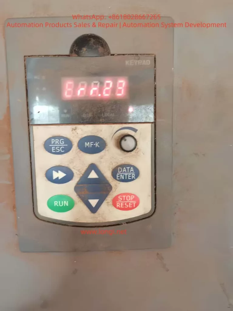
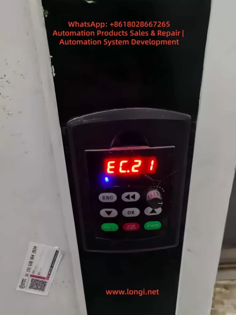
When a V600 series inverter triggers an EC.21 alarm, the operation panel typically displays the red code “EC.21” (or similar alphanumeric variations depending on the specific firmware version). This visual indicator is accompanied by a sequence of operational changes:
- Immediate Trip/Stop: The inverter usually halts output to the motor immediately to prevent damage.
- Cooling Fan Anomaly: The control logic for the cooling fan may fail. You might observe the fan stopping completely, running at an erratic speed, or failing to ramp up during high-load operations.
- Thermal Accumulation: Without valid temperature data, the inverter cannot regulate its internal thermal environment. The heatsink temperature may rise rapidly, often triggering secondary protections like “Overheating” (if a backup thermal switch exists) or “Overcurrent” due to IGBT performance degradation at high temperatures.
- Performance Derating: Even if the drive attempts to run, it will likely limit the output frequency and current to a “safe” but inefficient level, causing the motor to stall or run unevenly.
The core issue is a loss of telemetry. The microcontroller unit (MCU) has lost the ability to “see” the temperature of the critical components (usually the IGBT module or the main heatsink), forcing it into a defensive “safe mode.”
2. The Mechanism: Why EC.21 Happens
To solve the problem, one must understand the physics and electronics behind it. The V600 series typically employs an NTC (Negative Temperature Coefficient) Thermistor as the primary temperature sensing element.
The Operational Principle:
An NTC thermistor is a resistor whose resistance decreases as temperature increases. The inverter’s mainboard supplies a small excitation voltage (often 5V or 3.3V) to the thermistor via a precision resistor, creating a voltage divider circuit. The resulting voltage is read by the MCU’s Analog-to-Digital Converter (ADC). The MCU then uses a lookup table or a mathematical formula (Steinhart-Hart equation) to convert this voltage into a temperature value (°C).
Failure Modes:
The EC.21 alarm is triggered when the measured voltage falls outside the expected operational window. This generally stems from two distinct categories:
Category A: Signal Chain Integrity Failure
- Open Circuit: The wire is broken, or the connector is unplugged. The ADC reads maximum voltage (Vcc), interpreting it as an “infinite” resistance, which the logic interprets as a sensor failure or -273°C (absolute zero), both of which are invalid.
- Short Circuit: The signal line is shorted to ground. The ADC reads 0V, interpreting it as 0 Ohms (infinite temperature), triggering an immediate fault.
- Contact Resistance: Oxidation or loose pins create high resistance in the connector. This adds to the thermistor’s value, causing the MCU to read a temperature much higher than reality, potentially causing nuisance trips.
- EMI/RFI Interference: In high-noise environments (near large contactors or welding machines), electromagnetic interference can induce noise spikes on the sensor line, corrupting the ADC reading.
Category B: Sensor Body Failure
- Thermal Aging: Over years of operation, the chemical composition of the NTC bead degrades. Its resistance drifts out of specification (e.g., a 10kΩ sensor at 25°C might read 8kΩ or 15kΩ), causing calibration errors.
- Physical Damage: The sensor is often embedded in the thermal paste between the IGBT and the heatsink. If the encapsulation cracks due to thermal cycling (expansion/contraction), moisture can enter, causing corrosion or a short circuit.
- Incorrect Replacement: Using a non-OEM sensor with a different B-constant (sensitivity curve) will result in the MCU miscalculating the temperature, leading to persistent errors.
3. The Diagnostic Workflow: A Step-by-Step Protocol
Troubleshooting EC.21 requires a “Systems Engineering” approach. Do not simply replace parts randomly. Follow this tiered diagnostic process:
Phase 1: Safety & Preliminary Inspection (The “Zero Cost” Checks)
- LOTO (Lockout/Tagout): Isolate the inverter from the mains power. Wait at least 5–10 minutes for the DC bus capacitors to discharge. Verify 0V at the input terminals using a multimeter.
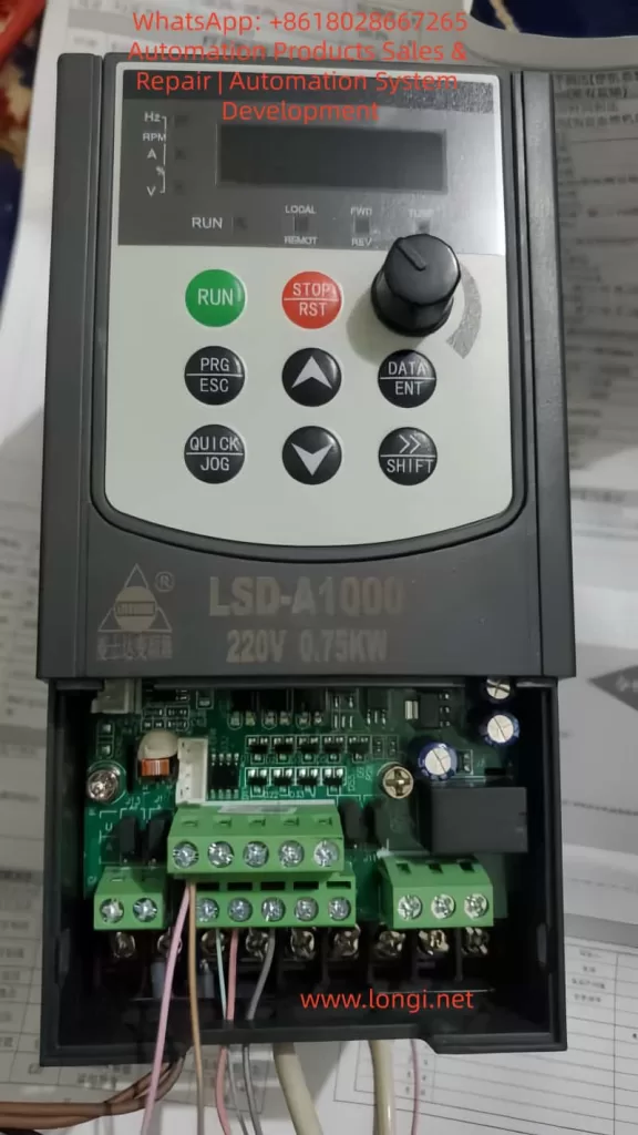
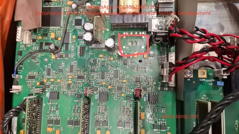
- Visual Inspection: Open the inverter chassis. Locate the temperature sensor (usually a two-wire cable leading from the mainboard to the heatsink or IGBT module).
- Check the Connector: Is it seated firmly? Look for black/green oxidation on the pins.
- Check the Cable: Look for fraying, cuts, or “wire work hardening” (stiffness indicating internal copper breakage).
- Check the Environment: Is the heatsink clogged with dust? Is there evidence of water ingress or oil contamination?
Phase 2: Signal Chain Verification (The “Electrical” Checks)
Tools: Multimeter, Megger (optional).
- Continuity Test: Disconnect the sensor plug. Measure resistance from the plug end to the mainboard header. It should be near 0Ω (<1Ω). If it is high or infinite, the wire or PCB trace is broken.
- Isolation Resistance (Megger Test): If moisture is suspected, use a 500V megger to test the insulation resistance between the sensor lines and the ground/heatsink. It should be >100MΩ.
- Voltage Injection Test (Simulation):
- Reconnect power (carefully).
- Disconnect the sensor.
- Use a precision decade resistance box or a known-good resistor (e.g., 10kΩ for a standard sensor) to bridge the connector pins on the cable side.
- If the EC.21 alarm clears and the drive runs, the Mainboard is functional, and the fault lies in the sensor or the cable on the heatsink side.
Phase 3: Sensor Performance Validation
Tools: Multimeter, Thermal Gun, Hair Dryer/Freezer Spray.
- Ambient Resistance Check: Measure the sensor’s resistance at room temperature. Compare it to the datasheet (e.g., 10kΩ ±1% at 25°C). If it reads 50kΩ or 0Ω, the sensor is dead.
- Thermal Response Test:
- Heat the sensor gently with a hair dryer (do not exceed 100°C). The resistance should drop smoothly and continuously.
- Cool it with freeze spray. The resistance should rise.
- Failure Indicator: If the resistance jumps erratically, lags significantly, or stays flat, the NTC element is fractured.
- Oscilloscope Analysis (Advanced): Hook a probe to the signal line while the drive is running (if possible). Look for high-frequency noise riding on the DC level. If noise exceeds 100mV p-p, shielding is inadequate.
Phase 4: Mainboard Forensics
If the sensor and wiring are perfect, the fault is on the MCU board.
- ADC Reference Voltage: Check the 5V/3.3V rail supplying the sensor circuit. Is it stable?
- Filtering Capacitors: Check the small ceramic or electrolytic capacitors near the ADC input pin. If they are shorted or open, the signal will be corrupt.
- Firmware/EEPROM: In rare cases, the calibration data stored in the EEPROM might be corrupted. Try a factory reset (consult the manual for the specific key combination).
4. Solutions and Remediation Strategies
Once the root cause is identified, apply the appropriate fix.
Scenario A: Wiring/Connector Issues
- Repair: Do not just twist wires. Solder the connection and use heat-shrink tubing with adhesive lining (marine grade) to prevent water ingress.
- Contact Enhancement: Clean oxidized pins with DeoxIT or Isopropyl Alcohol (IPA). Apply a thin layer of dielectric grease before mating the connectors.
- Shielding: If EMI is the culprit, wrap the signal pair in copper foil tape (grounded at one end only to avoid ground loops) or replace the cable with a shielded twisted pair (STP).
Scenario B: Sensor Replacement
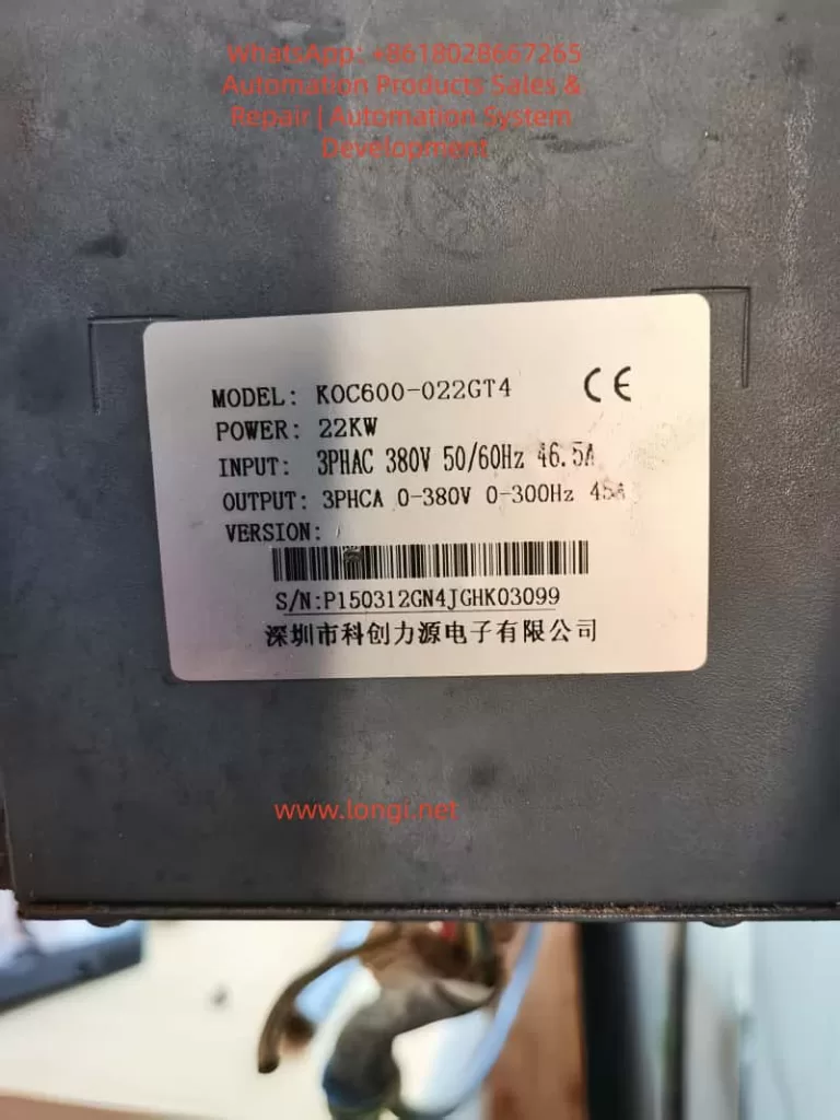
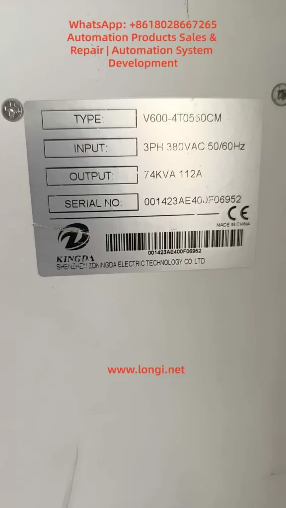
- OEM Sourcing: Critical. Do not use generic thermistors. Contact Kingda support with your Serial Number and Model (e.g., V600-4T0550CM) to get the exact part number.
- Installation Best Practices:
- Clean the mounting surface (heatsink/IGBT) with IPA to remove old, hardened thermal paste.
- Apply a high-performance thermal compound (e.g., Arctic MX-4 or equivalent).
- Ensure the sensor is flush against the surface. Use thermal tape or a spring clip if not screw-mounted.
- Torque: If screw-mounted, use a torque screwdriver. Over-tightening can crack the sensor; under-tightening creates an air gap (thermal insulator).
- Calibration: Some advanced V600 units allow “Sensor Offset” parameters. After replacement, you may need to run a self-tuning procedure or input a correction factor.
Scenario C: Environmental/Systemic Issues
- Cooling Upgrade: If the ambient temperature inside the cabinet exceeds 40°C, the sensor isn’t “failed”—it’s doing its job by tripping! Install cabinet coolers, exhaust fans, or air filters.
- Parameter Adjustment: Use with caution. You can slightly raise the “Temperature Warning Level” or “Temperature Trip Level” in the parameters (e.g., from 85°C to 90°C) to prevent nuisance trips, but never exceed the IGBT’s maximum junction temperature (usually 125°C-150°C).
5. Case Study: The “Ghost” Fault in a Humid Environment
Background: A textile factory reported intermittent EC.21 faults on three V600-4T0750CM drives. The maintenance team replaced the sensors twice, but the fault returned within two weeks.
Investigation:
- Visual: The factory floor had high humidity (>80%) and lint dust.
- Testing: The “old” sensors removed from the drive tested perfectly fine on a bench LCR meter. The wiring showed 5Ω resistance (high for a short run).
- Root Cause: Microscopic analysis revealed galvanic corrosion on the connector pins due to the humid, lint-filled environment. The lint absorbed moisture and acted as a wick, drawing humidity into the connector. The resistance increase mimicked a “high temperature” reading, triggering EC.21.
Resolution:
- Conformal Coating: The mainboard connector and sensor wires were sprayed with acrylic conformal coating (humidity protection).
- Sealed Connectors: Standard Molex connectors were replaced with IP67 rated circular connectors.
- Preventive Maintenance: The cabinet filters were upgraded to IP54, and a schedule for blowing out lint with compressed air was established.
Outcome: Zero EC.21 faults in the subsequent 12 months.
6. Preventive Maintenance & Lifecycle Management
Reactive repair is expensive. A proactive strategy is essential for the V600 series.
- Thermal Imaging: Use an infrared camera quarterly to scan the inverter heatsinks. Look for “hot spots” indicating poor contact between the IGBT and the heatsink (which the sensor might not detect if it’s mounted elsewhere).
- Vibration Analysis: If the inverter is on a vibrating machine, check connector tightness annually. Vibration loosens screws and fractures solder joints.
- Dust Management: Implement a “Clean Cabinet” policy. Dust is a thermal insulator. If the heatsink is coated in dust, the sensor will read high temps, and the components will age faster.
- Firmware Management: Check the Kingda website for firmware updates. Newer versions often include improved noise filtering algorithms for the ADC, which can eliminate false EC.21 triggers in electrically noisy environments.
7. Future Trends: The Evolution of Thermal Monitoring
As we move toward Industry 4.0, the way we handle EC.21 is evolving:
- AI-Driven Predictive Maintenance: Modern IoT-enabled VFDs don’t just report “Fault.” They upload temperature trends to the cloud. AI algorithms analyze the rate of change of temperature. If the temperature rises 2°C faster than usual under the same load, the system predicts a fan failure or clogged filter before the EC.21 threshold is breached.
- Wireless Sensor Networks: Instead of running analog wires (prone to noise), future retrofits may use Zigbee or LoRaWAN temperature nodes stuck directly onto the IGBTs, transmitting digital data wirelessly to the controller.
- Redundancy: Critical applications are moving toward “Dual Sensor” logic. If Sensor A disagrees with Sensor B by more than 5°C, the system flags a “Sensor Discrepancy” warning (allowing continued operation) rather than a hard trip, giving operators time to schedule maintenance.
Conclusion
The EC.21 (Temperature Sensor Fault) on a Shenzhen Kingda V600 inverter is a solvable problem, but it demands a methodical approach. It is rarely just a “bad part” issue; it is often a symptom of environmental stress, poor installation practices, or signal integrity degradation.
By adhering to the diagnostic hierarchy—Visual -> Wiring -> Sensor -> Board—engineers can isolate the fault efficiently. Furthermore, by implementing robust preventive measures like conformal coating, proper torque application, and environmental control, the recurrence of this fault can be virtually eliminated.
Final Safety Warning: All procedures involving the opening of the inverter chassis must be performed by qualified electrical personnel adhering to NFPA 70E or local equivalent safety standards. The DC bus capacitors retain lethal voltages even after power disconnection. Always verify zero energy state before touching internal components.
Mastering the resolution of EC.21 is not just about fixing a single error code; it is about mastering the thermal management of the entire drive system, ensuring longevity and reliability in the harshest industrial environments.