Frequency range limitation: F0-10 = 50.00Hz, F0-12 = 50.00Hz, F0-14 = 0.00Hz.
III. Fault Diagnosis and Handling
3.1 Common Fault Codes and Solutions
Fault Code
Fault Type
Possible Causes
Solutions
ERR02
Acceleration Overcurrent
Load mutation, short acceleration time
Check the load, increase the acceleration time F0-17
ERR03
Deceleration Overcurrent
Short deceleration time, large load inertia
Increase the deceleration time F0-18, install a braking resistor
…
…
…
…
ERR20
Encoder Fault
PG card fault, wiring error
Check the encoder wiring, set the F1-36 detection time
3.2 Fault Information Query and Reset
Fault History Query:
F9-14 to F9-16: Record the types of the last three faults.
F9-17 to F9-46: Record the operating status parameters at the time of the fault.
Fault Reset Methods:
Panel reset: Press the STOP/RES key.
Terminal reset: Set the DI terminal to 9.
Communication reset: Send a reset command through Modbus communication.
3.3 Fault Protection Action Settings
Fault Action Selection 1 (F9-47):
Units digit: Motor overload action.
Tens digit: Input phase loss action.
Fault Action Selection 2 (F9-48):
Units digit: Encoder fault action.
Tens digit: Parameter read/write abnormal action.
Fault Action Selection 3 (F9-49):
Units digit: Custom fault 1 action.
Tens digit: Custom fault 2 action.
IV. Advanced Functions and Application Examples
4.1 Multi-Motor Control Function
Motor Parameter Group Selection:
Select the current motor parameter group using F0-24.
Motor Parameter Settings:
First group: F1 group (motor parameters), F2 group (vector parameters).
Second group: A2 group (motor parameters), A5 group (vector parameters).
Switching Notes:
Switching must be performed in the stop state.
After switching, check the motor rotation direction.
4.2 PID Control Function Application
Basic Parameter Settings:
FA-00: PID setpoint source selection.
FA-02: PID feedback source selection.
PID Parameter Settings:
FA-05: Proportional gain Kp1.
FA-06: Integral time Ti1.
FA-07: Differential time Td1.
4.3 Communication Function Configuration
Basic Parameter Settings:
Fd-00: Baud rate setting.
Fd-01: Data format.
Fd-02: Local address.
Communication Control:
Run command: Communication address 0x1001.
Frequency setpoint: Communication address 0x1000.
V. Maintenance and Upkeep
5.1 Daily Maintenance Points
Regular Inspection Items:
Check the operation of the cooling fan.
Remove dust from the radiator.
Check the wiring terminals.
Check the electrolytic capacitors.
Maintenance Cycle Recommendations:
Daily: Check the operating status.
Monthly: Clean the radiator.
Annually: Conduct a comprehensive inspection.
5.2 Long-Term Storage Notes
Storage Environment Requirements:
Temperature: -20°C to +60°C.
Humidity: ≤95%RH (no condensation).
Inspection Before Reuse:
Measure the insulation resistance of the main circuit.
Check the control board.
5.3 Lifespan Prediction and Replacement
Lifespan Reference for Wear Parts:
Electrolytic capacitors: Approximately 8-10 years.
Cooling fans: Approximately 30,000-50,000 hours.
Replacement Notes:
Cut off the power supply and wait for 10 minutes before operation.
After replacement, check the parameter settings.
Conclusion
The XC-5000 series frequency converters are powerful and have superior performance. Through this guide, users can comprehensively master core skills such as operation panel usage, parameter settings, external control, and fault diagnosis. Correct installation, parameter settings, and maintenance are key to ensuring the long-term stable operation of the frequency converters. It is recommended that users refer to this guide and make appropriate adjustments according to specific working conditions to fully leverage the performance advantages of the XC-5000 frequency converters.
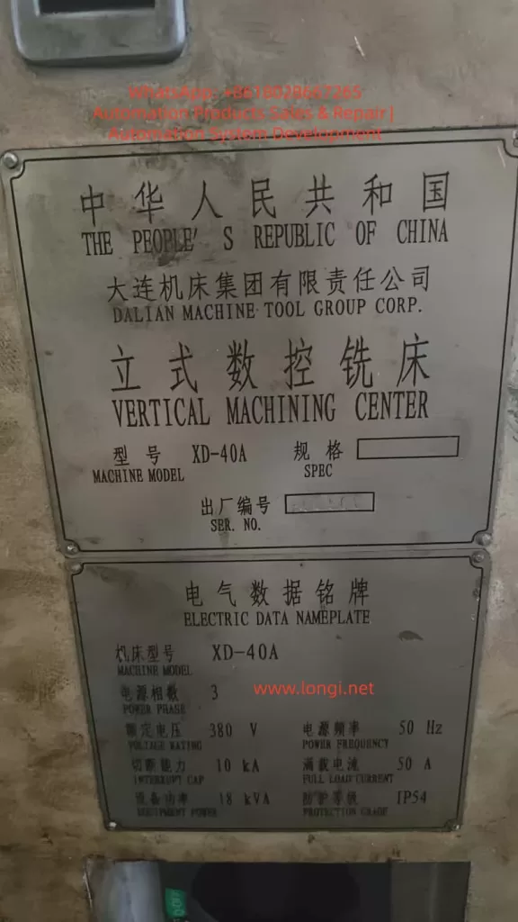
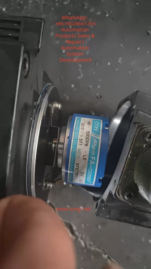
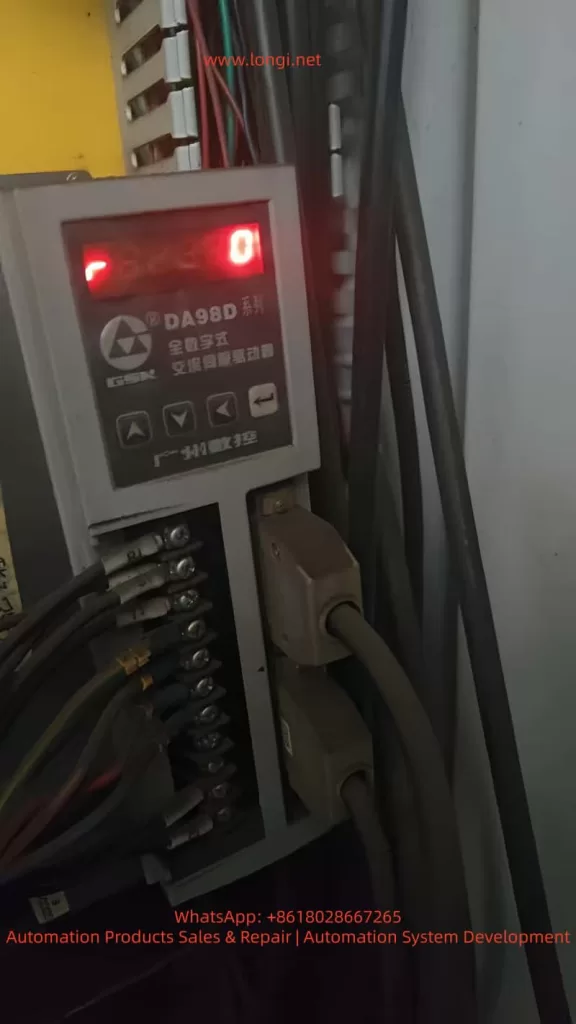
In CNC machining center maintenance and commissioning, the calibration of the Z-axis reference point and tool change point is critical for ensuring the machine’s precision and stability. This article takes the XD-40A vertical machining center manufactured by Dalian Machine Tool Group as an example. The machine is equipped with a GSK983Ma-H CNC system, DA98D servo drive, and a Sanyo OIH 5000P/R incremental encoder. The machine adopts an umbrella-type tool magazine, where the Z-axis must accurately position at the second reference point during tool change.
During routine maintenance, the Z-axis servo motor was replaced. After replacement, the machine could start and home normally, but an abnormality appeared during tool change (M06): The Z-axis stopped about 3 mm higher than before, causing the spindle taper to fail to engage the tool holder. The operator had to manually lower the Z-axis by 3 mm to complete the tool change.
Although this deviation did not trigger any alarms, it seriously affected the reliability of automatic tool change and could lead to tool gripper misalignment, incomplete release, or even tool crashes.
II. System Structure and Signal Relationship Analysis
To solve the issue, it is essential to understand how the GSK983Ma-H system defines the Z-axis “reference point (home position).” The Z-axis homing position is determined by two signals:
Proximity switch signal (HOME/ORG) – used for coarse positioning;
Encoder Z-phase signal (Z-phase) – used for fine positioning.
When the machine executes the “Home” (G28 Z0) command after power-up, the sequence is as follows:
The Z-axis moves in the specified direction until it detects the proximity switch signal.
The system records the pulse position at this point.
After the proximity signal is released, the axis continues moving.
When the next Z-phase pulse is detected, the system defines that position as the machine reference point (zero point).
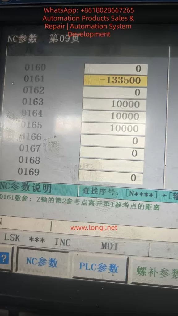
Based on parameter 0161, the system then calculates the second reference point (e.g., tool change point).
Thus, the Z-axis zero position is not determined by the limit switch alone, but by the phase relationship between the proximity signal and the encoder Z-phase pulse.
III. Root Cause Analysis After Motor Replacement
In this case, the proximity switch, lead screw, and limit mechanism remained unchanged, yet a 3 mm tool change deviation occurred after replacing the motor. The underlying causes are as follows:
1. Encoder Z-phase Signal Phase Difference
Even among identical motor models, the internal encoder Z-phase position relative to the rotor magnetic pole can vary slightly due to manufacturing tolerances. When the system executes “find proximity then find Z-phase,” a phase delay or advance changes the zero-point position.
For a 5000-line encoder: [ 5\text{ mm / rev} \Rightarrow 1 \text{ Z pulse = 5 mm} ] If the Z-phase triggers 0.6 turns later, the system’s reference point shifts upward by approximately 3 mm.
2. Coupling Installation Angle Deviation
If the motor–lead screw coupling is reassembled with a slight angular misalignment or reversed orientation, the timing between the proximity and Z-phase signals changes, causing a fixed offset.
3. Second Reference Point Parameter Not Recalibrated
Parameter 0161 in the GSK system defines the distance between the first and second reference points. If the old value is retained after encoder replacement, the stored Z-phase relationship becomes invalid, resulting in a tool change height deviation.
4. Servo Phase Angle or Polarity Mismatch
If the servo drive’s electrical phase offset (in DA98D) is not re-calibrated, it can cause inconsistent homing. However, such errors typically lead to random deviations, not a consistent 3 mm offset.
IV. Parameter Framework and Signal Interaction
The GSK983Ma-H system controls Z-axis referencing using several key parameters:
Parameter
Description
Function
0160
Home direction
Defines positive or negative direction of homing
0161
Distance from 1st to 2nd reference point
Defines tool change position
0162
Home offset
Compensates fine homing deviation (if available)
0163–0165
Homing speeds
Control homing speed at each stage
0171–0175
Home switch logic
Defines trigger mode and direction
Thus, the final tool change position can be expressed as: [ Z_{tool} = Z_{prox} + ΔZ_{Z-phase} + P_{0161} ] Any change in the above components—especially the Z-phase offset—will cause a physical shift in the tool change height.
V. Comparative Analysis of Available Solutions
When parameter modification (0161) is restricted by password protection, alternative methods must be considered. Below is a comparison of practical options used in the field.
Method
Principle
Application
Advantage
Risk
Modify 0161
Adjusts tool change offset
If password available
Accurate and safe
Requires password
Adjust proximity switch
Shifts home reference mechanically
No password
Simple and direct
Changes all Z references
Change servo electronic gear ratio
Alters pulses per unit
Mismatch in lead screw
Fixes scaling
Affects entire travel accuracy
Modify home offset (if available)
Software correction
Some versions only
No mechanical adjustment
Usually locked
Adjust motor phase
Alters encoder–rotor relationship
Encoder misalignment
Permanent correction
Complex, risky
Conclusion:
If password access is available, adjusting 0161 is best.
If not, physically adjusting the proximity switch by 3 mm is the most practical.
Avoid changing gear ratios unless lead screw or encoder specifications differ.
VI. Practical Solution Without Password Access
When the system password is unknown or locked, the following mechanical method effectively corrects the deviation.
1. Required Tools
Hex wrench, caliper or feeler gauge, insulation gloves, and a tool holder or alignment gauge.
2. Determine Adjustment Direction
If Z-axis stops too high → move the proximity switch upward.
If Z-axis stops too low → move the switch downward.
3. Adjustment Procedure
Power off the machine.
Loosen the Z-axis home switch screws.
Move the switch up by approximately 3 mm.
Tighten screws and power on.
Re-home the Z-axis and test tool change.
4. Verification
Execute:
G28 Z0
M06 T1
Check if the spindle taper aligns with the tool gripper. Fine-tune the switch by ±0.5 mm if needed.
5. Update Work Coordinate
Since the machine reference has shifted, redefine the Z=0 in G54 by touching off the workpiece again.
VII. DA98D Drive Parameter Verification
To ensure that the deviation is not caused by drive scaling, verify the following parameters in the DA98D servo drive:
Parameter
Function
Recommended
Description
P1.05
Electronic gear numerator
20000
Encoder output per rev
P1.06
Electronic gear denominator
1
1:1 transmission
P2.04
Home polarity
Depends on axis
Match direction
P4.01
Auto phase calibration
Execute after motor replacement
Syncs magnetic poles
Any incorrect electronic gear ratio can cause axis scaling errors and must be restored to 1:1.
VIII. Pulse Calculation for 3 mm Offset
Given:
Lead screw pitch = 5 mm
Encoder = 5000 PPR
Pulses per revolution = 5000 × 4 = 20000
Pulses per mm = 20000 ÷ 5 = 4000
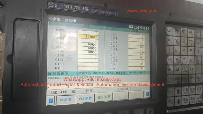
Then: [ 3 \text{ mm} × 4000 = 12000 \text{ pulses} ] To compensate for a 3 mm height difference, parameter 0161 should change by ±12000 pulses. For example:
0161: -133500 → -145500
IX. Unlocking System Parameters
If full software correction is preferred, parameter protection can be disabled as follows:
Navigate to: SYSTEM → PARAM → NC PARAM
Press SET;
When prompted, enter one of the following passwords:
Password
Description
983
GSK default
889
Service engineer code
1111 / 0000
User level
1314 / 8888
OEM-defined
After successful entry, “Protection Released” appears at the bottom of the screen, allowing parameter editing.
If unavailable, restart and hold DELETE or ALT+M during boot to enter the maintenance menu and disable “Parameter Protection.”
X. Understanding the Z-Axis Homing Logic
The following illustrates the Z-axis homing process:
From that zero, parameter 0161 defines the tool change position.
If the Z-phase occurs later relative to the proximity switch, the zero point shifts upward, making the spindle stop higher during tool change. By moving the proximity switch 3 mm upward, the zero point effectively moves downward by 3 mm, correcting the deviation.
XI. Key Lessons and Maintenance Practices
Always re-calibrate reference points after replacing incremental encoders. Even a small Z-phase shift can cause millimeter-level errors.
Back up all NC parameters before maintenance. Parameter loss or mismatch is a frequent cause of deviation.
Prefer software compensation over mechanical adjustments. Mechanical adjustments are practical but less precise.
Do not change electronic gear ratios arbitrarily. They affect all axis scaling, not just tool change height.
Umbrella-type tool changers rely heavily on parameter 0161. Incorrect values lead to failed or dangerous tool changes.
After adjustment, verify through a full test:
Home the Z-axis;
Execute tool change;
Check gripper alignment;
Recalibrate work coordinate (G54).
XII. Conclusion
This study analyzed a real case of Z-axis tool change deviation on an XD-40A vertical machining center equipped with GSK983Ma-H control and DA98D servo drives. Through a detailed investigation of encoder Z-phase behavior, servo drive settings, and CNC reference logic, it was concluded that the 3 mm deviation was caused by a Z-phase timing difference, not mechanical misalignment.
When parameter modification is possible, adjusting parameter 0161 is the optimal solution. When access is restricted, mechanically adjusting the proximity switch by 3 mm effectively compensates for the offset. If hardware specifications differ, recalibration of the electronic gear ratio is necessary.
This case highlights that CNC positioning precision depends not only on mechanical accuracy but also on the synchronization between hardware signals and software logic. A deep understanding of the system’s internal mechanisms allows technicians to restore functionality efficiently, accurately, and safely.
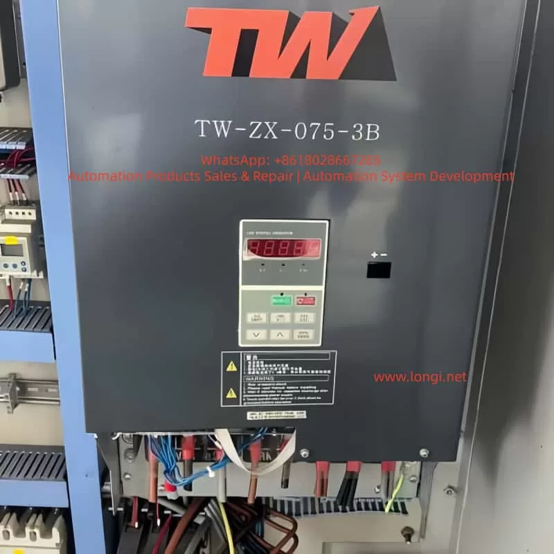
Preamble: Getting to Know the Weite TW-ZX Series Frequency Inverter
The Weite TW-ZX series frequency inverter is a high-performance drive control device specifically designed for lifting equipment. It is particularly suitable for precise control of heavy-duty machinery such as construction elevators and tower cranes. As a leading electrical transmission solution in the industry, this series of frequency inverters integrates advanced motor control algorithms and a rich set of functional configurations, enabling it to meet the stringent requirements of various lifting application scenarios.
This technical guide will comprehensively analyze the functional features, installation specifications, parameter settings, and maintenance essentials of the Weite TW-ZX frequency inverter, aiming to provide users with a systematic operational reference. By thoroughly understanding the content of this manual, users can fully leverage the performance advantages of the equipment, ensuring the safe, stable, and efficient operation of lifting equipment.
The TW-ZX series frequency inverter adopts optimized control algorithms specifically tailored for lifting applications, featuring core characteristics such as low-frequency high-torque output, intelligent braking control, and wide voltage adaptability. It is renowned in the industry for its high reliability and exceptional control precision. Below, we will commence with an overview of the product’s features and gradually unfold a complete application guide for this professional device.
I. Core Product Features and Technical Advantages
1.1 Professional Lifting Control Functions
The Weite TW-ZX frequency inverter is specifically designed for the lifting industry, incorporating a range of highly targeted professional functions:
Low-Frequency High-Torque Output: At 0.5Hz, it can provide 150% of the rated torque, ensuring stability during heavy-load startups and low-speed operations. This feature is particularly suitable for tower crane hoisting and elevator applications, addressing the industry challenge of insufficient torque in traditional frequency inverters at low frequencies.
Intelligent Brake Control Logic: It incorporates optimized braking timing control to precisely coordinate the actions of mechanical brakes and motors. Parameters Fb-00 to Fb-11 allow for flexible adjustment of brake release/closure frequencies and delay times, effectively preventing hook slippage and significantly enhancing operational safety.
Dynamic Current Limiting Technology: Advanced current control algorithms automatically adjust output during severe load fluctuations, preventing frequent overcurrent trips. Users can configure current stall protection characteristics via parameter FC-07 to balance system response speed and stability.
Wide Voltage Adaptability: The input voltage range extends up to 380V±20%, with automatic voltage regulation (AVR) functionality. It maintains sufficient torque output even when grid voltage drops, making it particularly suitable for construction sites with unstable grid conditions.
1.2 Hardware Design Characteristics
The TW-ZX series reflects the unique needs of lifting equipment in its hardware architecture:
Enhanced Cooling Design: The entire series adopts a forced air cooling structure with real-time protection against overheating of the散热器 (radiator) (OH fault), ensuring reliable operation in high-temperature environments. Larger power models (above 90kW) utilize an up-draft and down-draft air duct design to optimize cooling efficiency.
Modular Power Units: The power modules employ industrial-grade IGBT devices with an overload capacity of 150% rated current for 1 minute and 180% rated current for 10 seconds, fully meeting the short-term overload requirements of lifting equipment.
Rich Interface Configuration: It provides 7 multifunctional digital input terminals (X1-X7), 2 analog inputs (VS/VF for voltage signals, IS/IF for current signals), 2 open-collector outputs (Y1/Y2), and 1 relay output (R1), catering to complex control needs.
Built-in Brake Units (Select Models): Models below 18.5kW come standard with built-in brake units, allowing direct connection to brake resistors. Larger power models require external dedicated brake units, with the BR100 series recommended as a complementary product.
1.3 Control Performance Advantages
Compared to general-purpose frequency inverters, the TW-ZX series has undergone in-depth optimization in its control algorithms:
Optimized S-Curve Acceleration/Deceleration: Parameter FC-00 enables the S-curve acceleration/deceleration mode, with FC-01/02 setting the S-curve proportions for the acceleration and deceleration phases, respectively, effectively reducing mechanical shock and enhancing operational smoothness.
Multi-Speed Precise Control: It supports up to 16 preset speed stages (F3-00 to F3-14), allowing rapid switching through terminal combinations to meet the speed requirements of lifting equipment under various operating conditions. Each speed stage can independently set acceleration and deceleration times (F3-15 to F3-20).
Motor Parameter Self-Learning: It offers both stationary and rotational self-identification modes (F1-15) to automatically measure motor electrical parameters, significantly improving vector control accuracy. For applications where the load cannot be decoupled, the stationary identification mode provides a safe and reliable option.
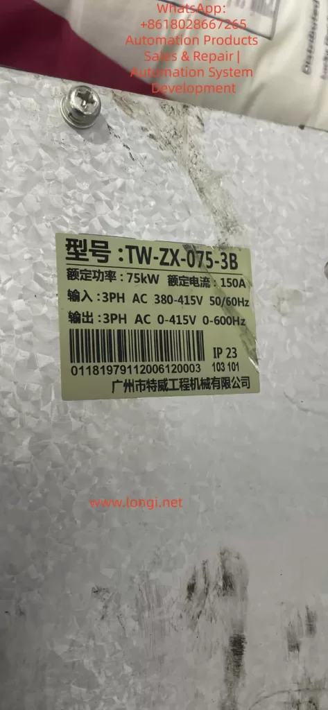
Table: Typical Models and Specifications of the TW-ZX Series Frequency Inverter
Model
Rated Power (kW)
Rated Current (A)
Brake Unit
Dimensions (mm)
TW-ZX-011-3
11
26
Built-in
270×200×470
TW-ZX-022-3
22
48
Built-in
386×300×753
TW-ZX-045-3
45
90
Built-in
497×397×1107
TW-ZX-110-3
110
220
External
855×825×793
II. Equipment Installation and Electrical Wiring Specifications
2.1 Mechanical Installation Requirements
Proper installation is fundamental to ensuring the long-term reliable operation of the frequency inverter. The TW-ZX series requires particular attention to the following points during installation:
Installation Orientation: It must be installed vertically to ensure unobstructed airflow through the cooling ducts. Sufficient space (recommended ≥100mm) should be left on all sides to prevent heat accumulation. When multiple frequency inverters are installed side by side in a control cabinet, the ambient temperature should not exceed 40℃.
Environmental Conditions: The operating environment should have a temperature range of -10℃ to +40℃ and a humidity range of 20% to 90%RH (non-condensing). It should be avoided in locations with conductive dust, corrosive gases, or oil mist, and kept away from vibration sources and electromagnetic interference sources.
Vibration Protection: The installation base should be sturdy and vibration-free, with a maximum allowable vibration of 0.5g. For vehicle-mounted or mobile equipment applications, shock absorbers are recommended to prevent internal components from loosening due to prolonged vibration.
Protection Level: Standard models have a protection level of IP20 and are not suitable for direct exposure to outdoor or humid environments. For special environments, customized protective enclosures or models with higher protection levels should be selected.
2.2 Main Circuit Wiring Specifications
The main circuit wiring directly affects system safety and EMC performance, and must strictly adhere to the following specifications:
Power Input Terminals (R/S/T):
A suitable circuit breaker (MCCB) must be installed, with a rated current of 1.5 to 2 times the rated value of the frequency inverter.
The power cable cross-sectional area should be selected according to Table 3-3, ensuring a voltage drop not exceeding 5V.
An AC reactor (optional) can be installed on the input side to suppress grid surges and harmonics.
Motor Output Terminals (U/V/W):
Motor cables should be shielded cables or laid through metal conduits to reduce electromagnetic radiation.
It is absolutely prohibited to install power factor correction capacitors or LC/RC filters on the output side.
When the motor wiring length exceeds 50 meters, the carrier frequency should be reduced or an output reactor should be installed.
Brake Resistor Connection:
For models with built-in brake units, connect to the PB terminals. For models with external brake units, connect to the P/N terminals.
The resistance value and power rating must be strictly selected according to Table 11-1 to prevent overload damage to the brake unit.
Brake resistor wiring must use high-temperature-resistant cables and be kept away from flammable materials.
Grounding Requirements:
The protective grounding terminal must be reliably grounded (Class III grounding, grounding resistance <10Ω).
The grounding wire cross-sectional area should be no less than half of the power cable cross-sectional area, with a minimum of 16mm².
When grounding multiple frequency inverters, avoid forming grounding loops and adopt a star grounding configuration.
2.3 Control Circuit Wiring Essentials
The control circuit serves as the bridge for interaction between the frequency inverter and external devices, and special attention should be paid to the following points during wiring:
Analog Signal Processing:
Speed reference signals (VS/VF) should use twisted-pair shielded cables, with the shield grounded at one end.
Signal lines should be separated from power lines by a distance of no less than 30cm and arranged perpendicularly when crossing.
Jumpers JP1/JP2 can select the analog output M0/M1 to operate in voltage (0-10V) or current (0-20mA) mode.
Digital Terminal Configuration:
By default, X1 is set for operation, X2 for forward/reverse rotation, and X3-X7 are programmable for functions such as multi-speed control (F2-00 to F2-06).
The PLC common terminal can be connected to either 24V or COM, supporting both NPN and PNP wiring modes.
The relay output R1 (EA-EB-EC) can directly drive contactor coils, with a contact rating of 250VAC/3A.
RS485 Communication:
Use shielded twisted-pair cables to connect the A+/A- terminals, with proper termination resistor matching.
Communication parameters are set via F1-16 to F1-19, supporting the Modbus RTU protocol.
It is recommended to set the baud rate not exceeding 19200bps and reduce the rate for long-distance communication.
Figure: Standard Wiring Diagram for the TW-ZX Frequency Inverter [Insert wiring diagrams similar to Figures 12-1 to 12-4 here, showcasing typical application wiring for elevators, tower crane hoisting, etc.]
III. Parameter Settings and Functional Configuration
3.1 Basic Parameter Setting Procedure
After powering on the TW-ZX frequency inverter, follow the procedure below for basic settings:
Restore Factory Settings:
Set F0-28=1 to restore the factory settings corresponding to the application macro.
Select F4-28=9 for elevator applications and F4-28=6 for tower crane hoisting applications.
After resetting, check F0-27=1 to ensure all parameter groups are displayed.
Motor Parameter Input:
Accurately input the motor nameplate data (F1-00 to F1-07).
For elevators with dual motors in parallel, set the power and current to the sum of the two motors.
The motor winding connection method (F1-06) must match the actual configuration (Y/△).
Motor Parameter Self-Learning:
Perform rotational self-identification (F1-15=2) after decoupling the load.
If the load cannot be decoupled, select stationary self-identification (F1-15=1).
Do not operate the frequency inverter during the identification process. Parameters are automatically stored upon completion.
Speed Control Parameters:
Set the maximum frequency F0-16 (usually 50Hz) and the upper limit frequency F0-17.
Adjust the acceleration time F0-09 and deceleration time F0-10, extending them appropriately for heavy loads.
The carrier frequency F0-14 is generally set to 1-4kHz, and can be increased if noise is significant.
Terminal Function Allocation:
Configure X3-X7 according to application requirements for functions such as multi-speed control and fault reset.
Set the output functions for Y1/Y2/R1, such as fault signals and brake control.
3.2 Configuration of Lifting-Specific Functions
The TW-ZX series requires special configuration for the unique functions tailored to lifting applications:
Brake Control Timing:
Set the ascending brake release frequency Fb-00 (usually 3Hz) and the descending release frequency Fb-01.
Configure the pre-release delay Fb-02 (approximately 0.3s) and the post-release delay Fb-03.
Set the brake closure frequencies Fb-04/Fb-11 and the corresponding delays Fb-05/Fb-06.
Zero-Crossing Acceleration Function:
Enable Fb-09 to set the zero-crossing acceleration/deceleration time (approximately 2s).
Adjust Fb-10 to set the frequency point for acceleration/deceleration changes (usually 2.5Hz).
Combine with S-curve parameters FC-01/02 to achieve smooth transitions.
Brake Inspection Function:
Set the inspection torque Fd-09 (150% of rated) and time Fd-10 (4s).
Define the inspection interval Fd-16 (e.g., 80 hours).
Set the Y2 terminal to provide a brake inspection reminder (F2-13=27).
Industry-Specific Protections:
Disable current limiting FC-07=0 and overvoltage stall FC-19=0010.
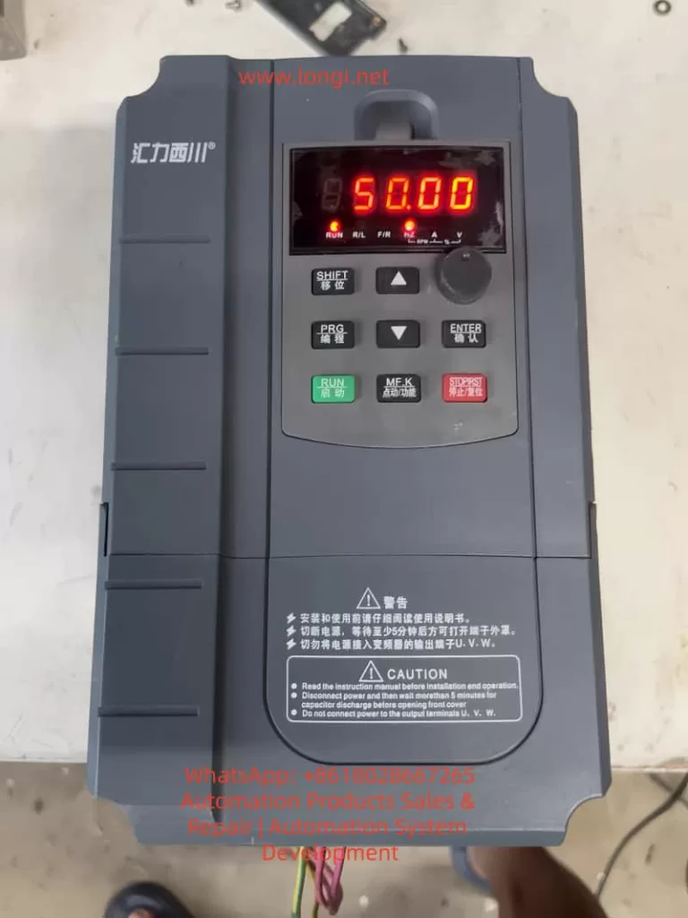
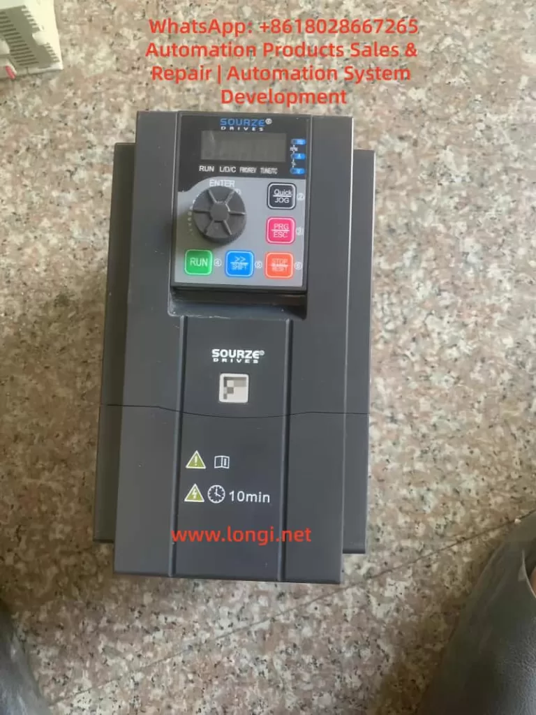
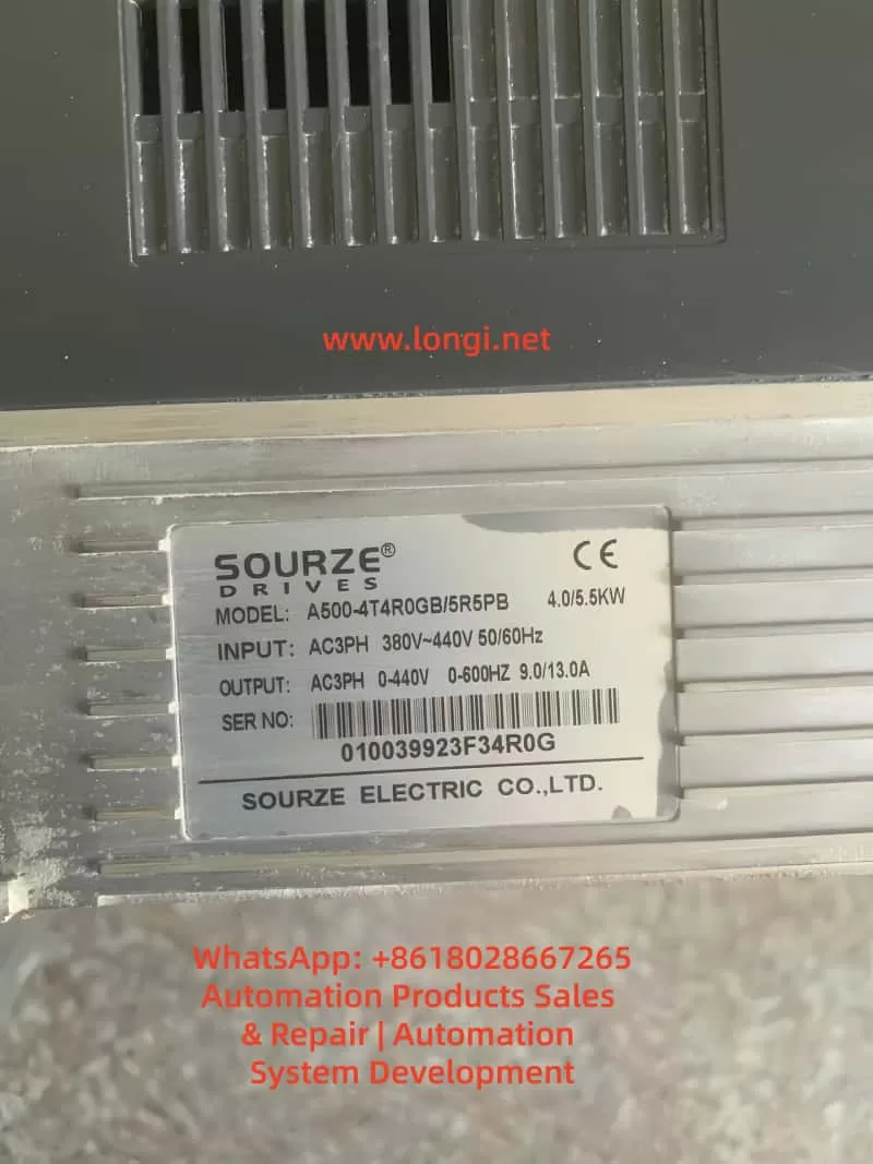
The operation panel of the Sourze A500/A500S frequency inverter is equipped with comprehensive control and display functions. Its interface is composed of the following elements:
Indicator Light Area:
Unit Indicator Lights (Hz/A/V/RPM/%): Display the current parameter units.
Running Status Indicator Light (RUN): Green indicates the running state.
Control Mode Indicator Light (L/D/C): Red indicates the current control mode (panel/terminal/communication).
Direction Indicator Lights (FWD/REV): Red indicates the forward/reverse running states.
Digital Display Area: A 5-digit LED display that can show the set frequency, output frequency, monitoring data, and alarm codes.
Keyboard Buttons:
PRG/ESC: Enter/exit the menu.
ENTER: Confirmation key.
+/-: Data increment/decrement.
>: Cycle through displayed parameters.
RUN: Running key.
STOP/RESET: Stop/reset key.
QUICK/JOG: Jog running/direction key.
2. Restoring Factory Parameters
Parameters can be initialized using function code A0-28:
Enter parameter A0-28 (parameter initialization operation).
Set it to 1: Restore factory parameters (excluding motor parameters, recorded information, and A0-20).
Press the ENTER key to confirm and execute.
The system will automatically return after completion.
3. Password Setting and Management
Setting a Password:
Enter A7-50 (user password).
Set it to a non-zero number (e.g., 12345).
The password protection will take effect after returning to the status interface.
After Password Protection is Activated:
Pressing the PRG key will display “—–“.
The correct password must be entered to view and modify function codes.
Incorrect entries will keep the display as “—–“.
Clearing the Password:
Enter the menu using the password.
Set A7-50 to 0.
The password protection function will be canceled.
4. Parameter Access Restriction Settings
Parameter read-only mode can be set using function code E0-00:
Enter E0-00 (function code read-only selection).
Set it to 1: All function codes except E0-00 can only be viewed but not modified, preventing accidental parameter changes.
II. External Terminal Control and Speed Adjustment Settings
1. External Terminal Forward/Reverse Control
Hardware Wiring:
Forward signal: Connect to the X(DI)2 terminal (default FWD function).
Reverse signal: Connect to the X(DI)4 terminal (default REV function).
Common terminal: COM terminal.
24V power supply: Provides power for external switches (optional).
Parameter Settings:
A0-04 = 1: Select the terminal command channel.
A5-01 = 1: Set X2(DI2) for forward running.
A5-03 = 2: Set X4(DI4) for reverse running.
A5-11 = 0: Select two-wire operation mode 1.
Control Logic:
SW1 closed: Forward running.
SW2 closed: Reverse running.
Both closed or open: Stop running.
2. External Potentiometer Speed Adjustment
Hardware Wiring:
Connect the three terminals of the potentiometer as follows:
Upper terminal: +10V.
Sliding terminal: AI1.
Lower terminal: GND.
Recommended potentiometer resistance: 1-5kΩ.
Parameter Settings:
A0-06 = 2: Select AI1 as the main frequency source.
A5-15 = 0.00V: Minimum input value for AI1.
A5-16 = 0.0%: Corresponding to 0.0%.
A5-17 = 10.00V: Maximum input value for AI1.
A5-18 = 100.0%: Corresponding to 100.0%.
Calibration Adjustment:
If the actual speed does not match the potentiometer position, adjust A5-15 to A5-18.
Different AI curve characteristics can be selected via A5-45.
III. Fault Diagnosis and Handling
1. Common Fault Codes and Solutions
Fault Code
Fault Name
Possible Causes
Solutions
Err12
Undervoltage Fault
Input power voltage too low
Check if the power voltage is within the allowable range (±20%)
Err14
Motor Overload
Excessive load or short acceleration time
Check the mechanical load and adjust the acceleration time in A0-23
Err20
Ground Short Circuit
Motor or cable insulation damage
Disconnect the inverter and check the motor insulation resistance (should be ≥5MΩ)
Err23
Input Phase Loss
Three-phase input phase loss
Check the input power wiring
Err24
Output Phase Loss
Motor or output cable fault
Check the output wiring and motor
Err27
Communication Fault
Communication interruption or format error
Check the communication line and confirm the settings in A8-00 to A8-05
Err28
External Fault
External fault terminal activation
Check the external fault signal source
Err29
Excessive Speed Deviation
Load突变 (sudden change) or inaccurate motor parameters
Retune the motor (A1-00 = 2)
2. Fault Reset Methods
Panel Reset: Use the STOP/RESET key.
Terminal Reset: Set any X(DI) terminal function to 9 (fault reset).
Automatic Reset: Set A9-11 (number of fault automatic resets) and A9-13 (reset interval time).
3. Fault Record Inquiry
Historical fault records can be viewed through the U0 group parameters:
U0-00 to U0-03: The last 4 fault codes.
U0-04 to U0-07: Corresponding running frequencies at the time of the faults.
U0-08 to U0-11: Corresponding output currents at the time of the faults.
U0-12 to U0-15: Corresponding DC bus voltages at the time of the faults.
IV. Advanced Function Applications
1. Multi-Speed Control
Setting Steps:
A0-06 = 4: Select multi-speed as the frequency source.
Set AC-00 to AC-15: Define 16 speed frequency values.
Allocate X(DI) functions: Set A5-00 to A5-04 to 12 to 15 (multi-speed terminals 1 to 4).
Combination Control:
Through 4 DI terminals, 16 states can be combined (binary 0000 to 1111).
Each state corresponds to one of the frequency values in AC-00 to AC-15.
2. PID Control Application
Basic Settings:
A0-06 = 6: Select PID as the frequency source.
AA-00: Select the PID setpoint source (e.g., AI1).
AA-03: Select the PID feedback source (e.g., AI2).
AA-04: Set the PID action direction (0 for positive, 1 for negative).
Parameter Adjustment:
AA-06: Proportional gain (increase to speed up response).
AA-07: Integral time (decrease to eliminate steady-state error).
AA-08: Derivative time (improve dynamic characteristics).
3. Frequency Sweep Function
Suitable for the textile and chemical fiber industries:
Ab-00 = 0: Sweep amplitude relative to the center frequency.
Ab-01 = 30.0%: Set the sweep amplitude.
Ab-03 = 10.0s: Set the sweep frequency period.
Ab-04 = 50.0%: Triangular wave rise time coefficient.
V. Maintenance and Upkeep
1. Daily Inspection Items
Check for abnormal motor running sounds.
Check motor vibration.
Check the operation status of the inverter’s cooling fan.
Check for overheating of the inverter.
2. Regular Maintenance
Clean the air duct dust every 3 months.
Check the tightness of screws.
Check the wiring terminals for arc traces.
Use a 500V megohmmeter to test the main circuit insulation (disconnect the inverter).
3. Replacement Cycles for Wear Parts
Cooling fan: 2-3 years (depending on the usage environment).
Electrolytic capacitor: 4-5 years.
4. Long-Term Storage Precautions
Store in the original packaging.
Power on every 2 years (for at least 5 hours).
The input voltage should be raised slowly to the rated value.
Conclusion
The Sourze A500 series frequency inverter is powerful and flexible, capable of meeting various industrial application requirements through reasonable settings. This guide provides a detailed introduction to the entire process, from basic operations to advanced applications. It is recommended that users carefully read the relevant sections of the manual before use, especially the safety precautions. For complex application scenarios, it is advisable to contact the manufacturer’s technical support for professional guidance.
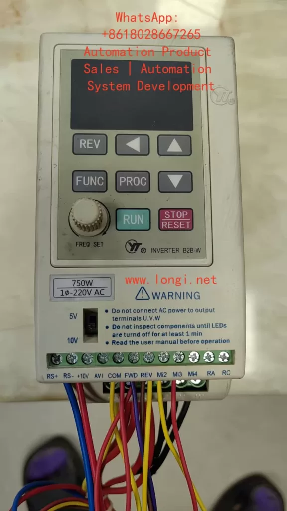
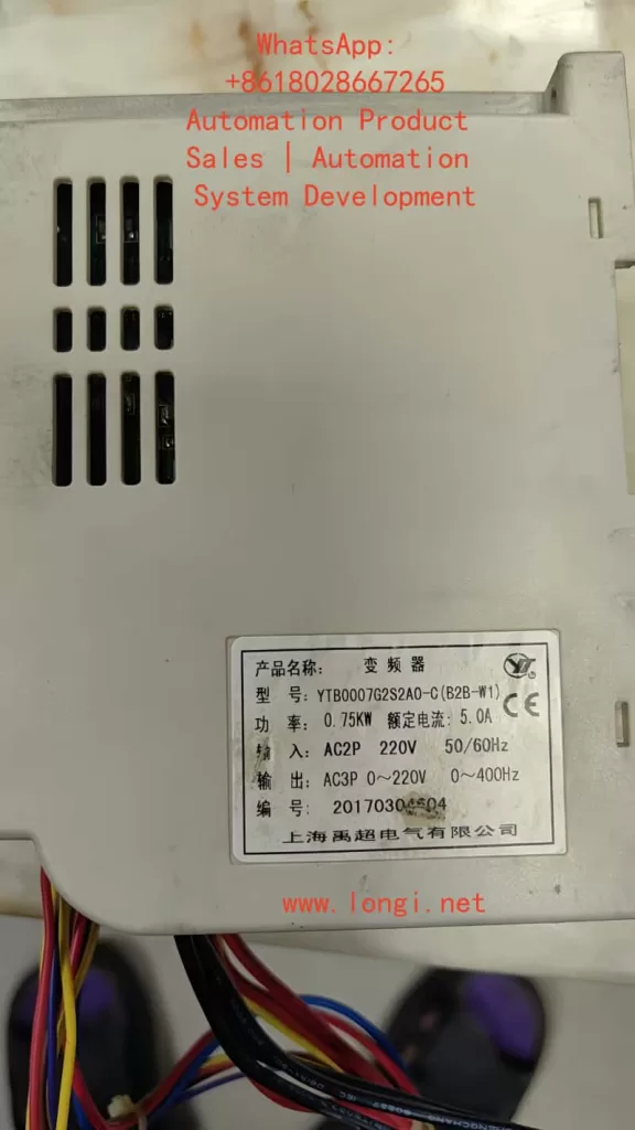
Operation Panel Functions and Parameter Settings 1.1 Operation Panel Features
The YTA/YTB series features a 4-digit LED display panel with:
Status indicators: RUN (operation), STOP (stop), CTC (timer/counter), REV (reverse) Function keys: FUNC: Parameter setting PROC: Parameter save ▲/▼: Frequency adjustment FWD/REV: Forward/reverse control STOP/RESET: Stop/reset 1.2 Password Protection and Parameter Initialization
Password Setup:
Press FUNC to enter parameter mode Set D001 parameter (user password) to 1 for unlocking Restore to 0 after modification to lock parameters
Factory Reset:
Unlock parameters (D001=1) Locate D176 parameter (factory reset) Set to 1 and press PROC to execute initialization
External Control Implementation 2.1 External Terminal Forward/Reverse Control
Wiring:
Forward: Connect FWD terminal to COM Reverse: Connect REV terminal to COM Common: COM terminal
Parameter Settings:
D032=1 (external terminal control) D096=0 (FWD for forward/stop, REV for reverse/stop) D036=2 (allow bidirectional operation) D097 sets direction change delay (default 0.5s) 2.2 External Potentiometer Speed Control
Wiring:
Potentiometer connections: Ends to +10V and COM Wiper to AVI terminal AVI range selection via DIP switch (0-5V or 0-10V)
Parameter Configuration:
D031=1 (frequency source from AVI) Match potentiometer output range with DIP switch Set D091-D095 for analog-frequency mapping
Fault Diagnosis and Solutions 3.1 Common Error Codes Code Meaning Solution Eo/EoCA Overcurrent Increase acceleration time (D011) EoCn Running overcurrent Check load/motor condition EoU Overvoltage Extend deceleration time (D012) EoL Overload Reduce load or increase capacity ELU Undervoltage Check power supply voltage 3.2 Maintenance Guidelines
Regular Checks:
Clean heat sinks and vents every 3 months Verify terminal tightness Monitor operating current Record fault history (D170-D172)
Advanced Functions 4.1 PLC Programmable Operation
Configuration:
D120=1/2/3 (select single/cyclic/controlled cycle) D122-D136 set segment speeds D141-D156 set segment durations D137/D138 set direction for segments 4.2 PID Closed-loop Control
Setup:
D070=1 (enable PID) D072-D074 set P/I/D parameters Connect feedback signal to ACI terminal (4-20mA) Set target value via AVI or panel 4.3 RS485 Communication
Parameters:
D160: Station address (1-254) D161: Baud rate (4800-38400bps) D163: Communication format (8N2 RTU mode)
This guide covers all operational aspects from basic controls to advanced applications of Yuchao YTA/YTB series inverters. For complex issues, please contact us.
Variable Frequency Drives (VFDs) play an increasingly critical role in water supply, HVAC, and industrial automation. Beyond simple motor speed control, VFDs are now deeply integrated into supervisory systems, exchanging data with PLCs and HMIs to enable centralized control and monitoring.
However, in real-world operation, communication faults are not uncommon. In particular, when multiple drives are connected in a network, a single issue can sometimes cause a complete loss of communication across all devices, leading to system downtime.
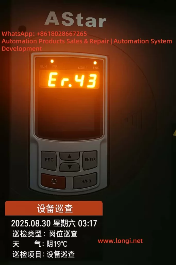
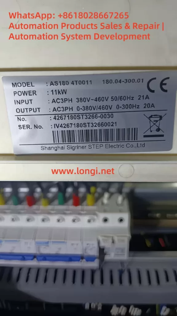
This article examines a case involving three AS180 series VFDs manufactured by STEP Electric in a water supply system. The drives simultaneously reported Er.43 communication fault codes, and the HMI displayed “Communicating…”. By analyzing the fault mechanism and field conditions, we summarize the causes, provide structured troubleshooting steps, and present practical solutions.
2. Fault Description
2.1 System Overview
The system consists of three 11 kW AS180 VFDs, each driving a water pump. The VFDs are connected to a PLC and an HMI, forming an intelligent constant-pressure water supply system. Both the run command and frequency reference for the drives are configured to be received via the RS-485 communication interface, using the Modbus-RTU protocol.
2.2 Fault Symptoms
During operation, all three VFDs displayed “Er.43” on their front panels simultaneously. The HMI screen froze with the message “Communicating…”, while the PLC could no longer read current, frequency, or pressure data from the drives. This effectively disabled automatic control of the pumps.
2.3 Manual Interpretation
According to the AS180 manual, fault code 43 is defined as:
Communication fault – No communication data received within the specified time window.
This indicates that the VFDs did not detect any polling signal from the master device (PLC/HMI) during the configured timeout period, thus triggering communication loss protection.
3. Root Cause Analysis
The simultaneous occurrence of Er.43 alarms across all three VFDs suggests that the problem was not isolated to an individual drive. Instead, the issue likely originated from the master device or the RS-485 bus. The potential causes can be categorized as follows:
3.1 Master Device Failure
If the PLC or HMI fails to transmit Modbus queries, the drives will all report a communication fault. Possible reasons include:
PLC/HMI power supply failure or reset;
Serial communication module failure or gateway malfunction (RS-232/485 converter);
Software/program crash, leaving the serial port idle.
3.2 RS-485 Physical Layer Issues
The RS-485 bus is inherently sensitive to wiring quality and terminations. Typical physical-layer issues include:
Open circuit or miswiring of A/B lines;
Reversed polarity (A and B swapped);
Multiple or missing termination resistors, causing reflections;
Absence of bias resistors, leaving the bus floating;
Poor shielding or proximity to high-voltage cables, leading to EMI.
3.3 Parameter Configuration Errors
If the drives and master are not configured with consistent communication parameters, the entire system may fail:
Inconsistent baud rate, parity, or stop bits;
Duplicate station addresses causing response conflicts;
VFD command channel not set to “communication reference.”
3.4 Electromagnetic Interference
In pump rooms or industrial sites, large motors and contactors switch frequently, generating strong electromagnetic noise. If RS-485 wiring runs parallel to power cables without proper shielding, frame loss or CRC errors can occur, leading to timeouts and Er.43 alarms.
1000077
4. Structured Troubleshooting Steps
Based on experience, the following step-by-step troubleshooting process is recommended:
Step 1: Verify Master Device Status
Check that PLC/HMI power supplies are stable;
Observe communication LED indicators on the PLC serial port or gateway;
If necessary, reboot the PLC/HMI and check whether VFD alarms clear;
If the master does not transmit at all, the problem lies upstream.
Step 2: Inspect Wiring Integrity
Use a multimeter to check continuity of A/B lines;
Verify there is no short circuit to ground;
Confirm polarity is correct (A to A, B to B);
Ensure terminals are properly tightened.
Step 3: Check Communication Parameters
Each VFD must have a unique station address (e.g., 1, 2, 3);
Baud rate, parity, and stop bits must match the PLC settings;
Run and frequency command channels must be set to “communication.”
Step 4: Adjust Timeout Settings
Parameter P94.19 (communication timeout) can be temporarily increased from the default 2 seconds to 5–10 seconds to reduce nuisance trips during debugging;
Parameter P94.18 (communication loss protection) should remain enabled for system safety.
Step 5: Mitigate Interference
Use shielded twisted-pair cable for RS-485 wiring;
Connect the shield to ground at one end only;
Keep communication wiring at least 30 cm away from power cables;
Route communication lines separately whenever possible.
Step 6: Isolate and Test Individually
Disconnect two VFDs, leaving only one connected to the master;
Verify stable communication with a single device;
Reconnect drives one by one to determine if issues are related to wiring topology or specific devices.
5. Case Study Findings
During on-site troubleshooting of this specific case, the following observations were made:
All three drives had consistent parameters, with station numbers 1, 2, and 3;
RS-485 cabling was intact, but termination resistors were mistakenly installed on all three drives, rather than only at the two ends of the bus;
The PLC serial module was intermittently freezing in the noisy environment, causing polling to stop;
The HMI simply displayed “Communicating…” while awaiting PLC responses.
Corrective Actions Taken
Removed redundant termination resistors, leaving only one at each end of the RS-485 bus (120 Ω each);
Added bias resistors (1 kΩ pull-up/pull-down) to stabilize the bus idle state;
Improved shielding and grounding of the communication line;
Replaced the PLC serial port module and implemented a watchdog function in software.
Outcome
After implementing these measures, the three drives resumed stable communication. The Er.43 alarms disappeared, and the water supply system returned to normal automatic operation.
6. Lessons Learned and Best Practices
From this case, several important lessons can be drawn:
Simultaneous alarms across all drives usually point to the master device or the RS-485 backbone, rather than the drives themselves.
Follow RS-485 wiring standards strictly. Proper termination, biasing, and shielding are essential for stable communication.
Tune communication protection parameters wisely. Extending the timeout can reduce nuisance trips during debugging, but should be optimized during commissioning.
EMI is a real threat. In pump rooms and industrial settings, interference must be mitigated through careful routing and shielding.
Equip maintenance teams with RS-485 analyzers. These tools can quickly identify whether polling frames are transmitted and whether responses are correct, greatly accelerating troubleshooting.
7. Conclusion
The AS180 VFD is widely applied in water supply and industrial systems, but communication reliability is crucial for its proper operation. The Er.43 communication fault is not typically caused by defects in the VFD itself, but by issues in the RS-485 bus or master station.
By applying a systematic troubleshooting approach—from verifying the master, inspecting wiring, checking parameters, to mitigating interference—engineers can quickly locate and resolve the root cause.
This case study demonstrates that once proper RS-485 wiring practices were restored and the PLC module replaced, the system regained full stability.
For operators and maintenance engineers, this provides both a reference case and a practical methodology to handle similar faults effectively in the future.
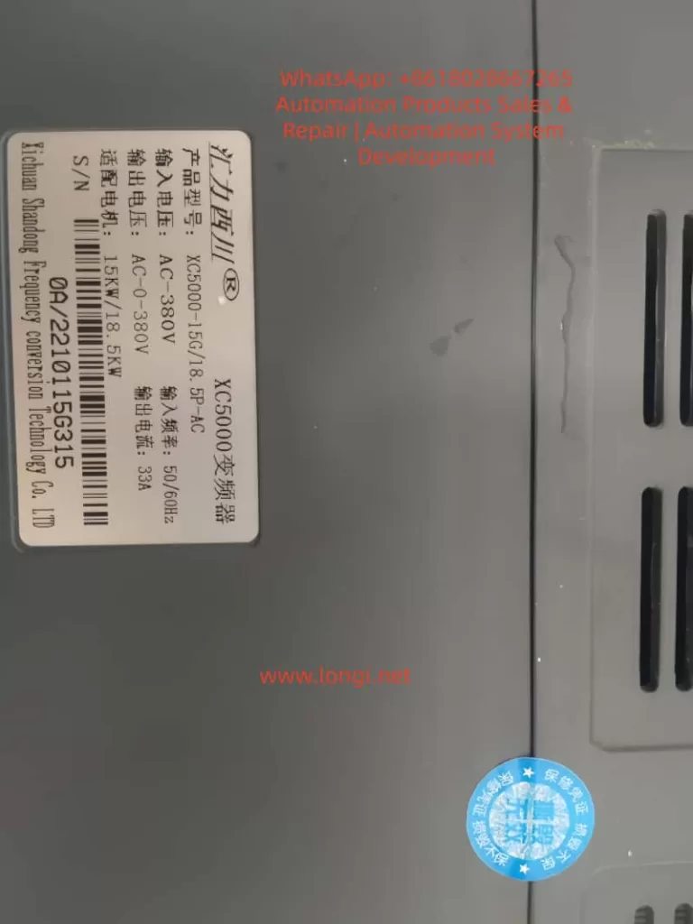
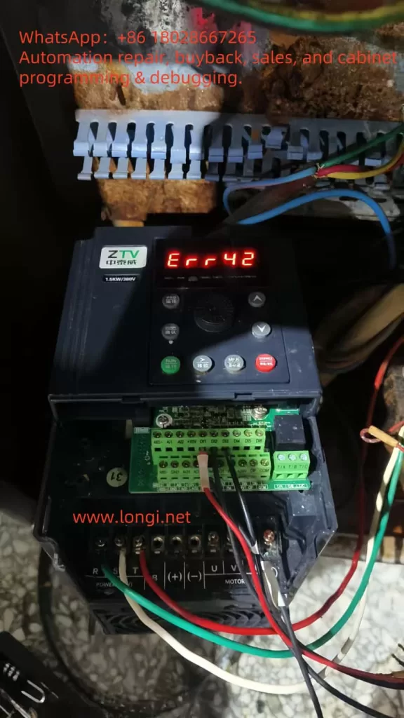
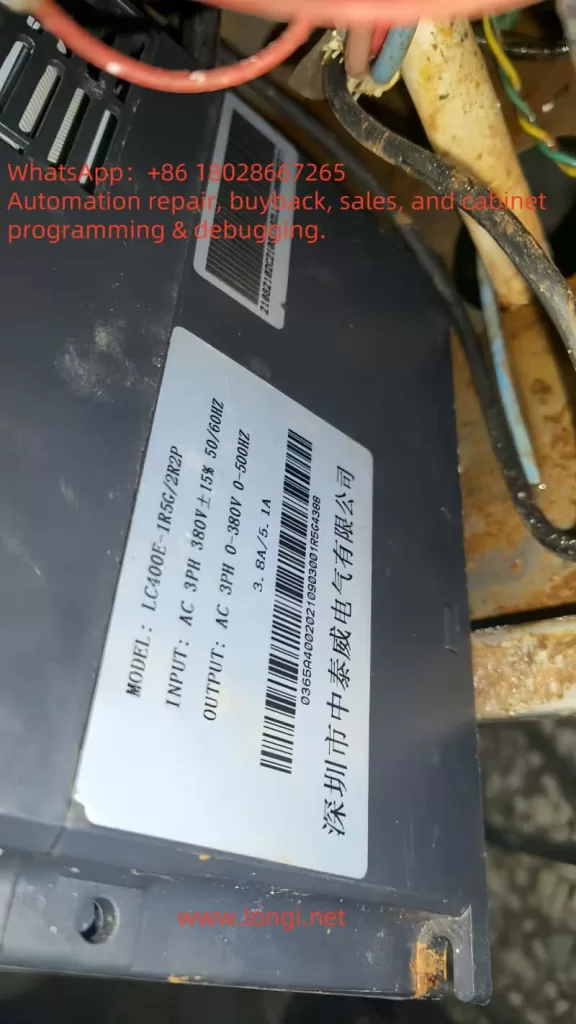
In the realm of modern industrial automation, variable frequency drives (VFDs) serve as the cornerstone of motor control systems. They enable precise regulation of motor speed and torque, facilitating energy efficiency and optimal performance, particularly in applications such as machinery manufacturing, fan and pump loads, and elevators. ZTV (Zhong Tai Wei), a prominent Chinese manufacturer of VFDs, is renowned for its LC400E series, which offers high cost-effectiveness and reliable operation. This series supports three-phase 380V input, with power ratings starting from 1.5kW and extending to higher capacities, making it suitable for diverse industrial environments. However, like all electronic devices, the LC400E VFD is susceptible to faults during operation. Among these, the Err42 error code is a frequently encountered alarm, signifying an “excessive speed deviation fault.” This issue can halt motor operation, disrupt production efficiency, and potentially lead to equipment downtime.
Based on the ZTV LC400E VFD manual and the provided fault screenshots, the Err42 fault typically arises from a significant discrepancy between the motor’s actual speed and the set speed. If this deviation exceeds a predefined threshold, the VFD initiates a protective shutdown to prevent further damage to the motor or load. Understanding and resolving this fault not only allows for swift restoration of operations but also enhances the overall reliability of the equipment. This article delves into the Err42 fault, covering its definition, root cause analysis, diagnostic procedures, resolution strategies, preventive measures, and real-world case studies. It aims to provide a structured, logically sound, and practical guide for engineers and maintenance personnel. The content draws from the official manual, on-site experiences, and relevant technical literature to ensure accuracy and applicability.
Overview of Err42 Fault
The Err42 fault manifests on the LC400E VFD’s display screen in red text, often accompanied by a buzzer alarm or flashing indicator lights. The code “Err42” directly translates to “excessive speed deviation,” representing a protective mechanism primarily in closed-loop control modes. In the VFD’s operational principle, motor speed control relies on comparing feedback signals (such as those from an encoder providing actual speed) with the setpoint speed. When the actual speed deviates excessively from the setpoint, the VFD triggers this alarm.
Specifically, the LC400E series supports various control modes, including V/F control, open-loop vector control, and closed-loop vector control. In closed-loop mode (when parameter P0-01 is set to 1), encoder feedback is critical. If the deviation is too large, the VFD immediately ceases output to avert motor instability or overload. Symptoms include: the motor starting briefly before stopping, the VFD panel displaying Err42, abnormal fluctuations in output current, and possibly mechanical vibrations or unusual noises. According to the manual, this fault’s trigger threshold correlates with parameter P2-10 (speed deviation setpoint), typically defaulting to a percentage like 5%-10%, depending on the model.
Why is this fault significant? In industrial settings, excessive speed deviation not only interrupts production but can also cause chain breaks, product defects, or safety hazards. For instance, in fan applications, unstable motor speed leads to fluctuating airflow, compromising ventilation systems; in pump loads, it results in pressure instability, affecting process flows. Statistics indicate that speed-related issues account for about 15%-20% of VFD faults, with Err42 being a typical example. Early identification and resolution can substantially reduce downtime and maintenance costs.
Possible Causes of Err42 Fault
To effectively address the Err42 fault, a thorough examination of its underlying causes is essential. Drawing from the LC400E manual and the fault table screenshot, here are the five primary causes, each explained with practical scenarios:
Incorrect Encoder Parameter Settings: In closed-loop vector control mode (P0-01=1), the encoder is pivotal for speed feedback. If parameters such as P9-69 (encoder type) or P9-70 (encoder pulses per revolution) are misconfigured, the VFD cannot accurately interpret the actual speed, leading to erroneous deviation calculations. For example, if the actual encoder is incremental but set as absolute, signal mismatches occur.
Incomplete or Absent Motor Auto-Tuning: The LC400E VFD mandates motor parameter auto-tuning (initiated via P9 group parameters) before use. If tuning is interrupted (e.g., due to power fluctuations) or skipped, the VFD’s understanding of motor parameters like resistance and inductance becomes inaccurate, impairing speed control precision. The manual stresses that auto-tuning is a prerequisite for closed-loop control, and neglecting it often triggers Err42.
Too Small Speed Deviation Setpoint: Parameter P2-10 defines the allowable speed deviation threshold. If set too low (below the actual load fluctuation range), even minor deviations can activate the alarm. This is common in applications with variable loads, such as conveyor belts where torque spikes during startup.
Sudden Load Increases: External factors like mechanical jamming, overload, or loose transmission chains can cause the actual motor speed to lag behind the setpoint. While the VFD’s U, V, W phase outputs to the motor remain normal, excessive load resistance accumulates deviation.
Wiring Abnormalities: Issues at the VFD’s output terminals U, V, W and the motor connections are the most prevalent hardware faults. These include cable breaks, poor contacts, incorrect phase sequences, or grounding problems, which disrupt feedback signals or output power, indirectly exacerbating speed deviations.
Additionally, environmental factors such as high temperatures, dust accumulation, or unstable power supplies can indirectly contribute to Err42. In practice, these causes often interplay; for instance, parameter errors can amplify load effects, resulting in frequent faults.
Diagnostic Steps for Err42 Fault
Diagnosis is the cornerstone of fault resolution and should be conducted systematically. The following process is derived from the LC400E manual, prioritizing safety (power off during operations):
Initial Equipment Status Check: Observe the VFD panel to confirm the Err42 code. Record the alarm time, operating frequency, and load conditions. Use a multimeter to measure input voltage (AC 3PH 380V ±15%), ensuring it’s within normal limits.
Parameter Settings Review: Enter parameter mode (by pressing the PRG key) and verify if P0-01 is set to 1 (closed-loop mode). Check P9-69 and P9-70 for encoder parameter alignment with actual hardware. The manual recommends cross-referencing motor nameplate data.
Motor Auto-Tuning Test: If auto-tuning hasn’t been performed, initiate it via P9 group functions for static or dynamic tuning. This requires no-load conditions and lasts a few minutes. After completion, restart the VFD to see if the fault recurs.
Speed Deviation Measurement: Monitor group parameters (e.g., d0-00 for actual speed, d0-01 for setpoint speed) to calculate the deviation. If it consistently exceeds the P2-10 setpoint, classify it as a software issue.
Hardware Inspection: After powering off, examine U, V, W output cables. Use a megohmmeter to test insulation resistance (>5MΩ is normal). Manually rotate the motor shaft to check for mechanical resistance. If available, use an oscilloscope to monitor encoder signal waveforms for distortions.
Environmental Assessment: Inspect the VFD’s installation site to avoid humidity or excessive heat (operating temperature: -10°C to 40°C). Clean dust and confirm fan operation.
Document the diagnostic process in a log for future reference. If initial diagnostics fail, draw from experiences with similar brands, like ZHZK inverters where Err42 often stems from control mode conflicts.
Solutions for Err42 Fault
Tailored to the identified causes, here are step-by-step solutions. Ensure equipment is powered off and operations are performed by qualified personnel:
Correct Encoder Parameters: Access the P9 group, set P9-69 to the proper encoder type (e.g., 0 for none, 1 for ABZ incremental). Input the pulse count in P9-70 (from motor nameplate or measurement). Save and restart for testing.
Perform Motor Auto-Tuning: Set P9-00 to 1 (static) or 2 (dynamic), then press RUN to start. Parameters update automatically upon completion. The manual cautions: perform tuning without load.
Adjust Speed Deviation Setpoint: Increase P2-10 (e.g., from 5% to 10%), but avoid excessive values to maintain control accuracy. Test incrementally while monitoring deviations.
Address Load Issues: Inspect mechanical connections, tighten chains or belts. Reduce load or extend acceleration/deceleration times (P0-13, P0-14). For frequent load surges, consider upgrading VFD power (LC400E-1R5G is 1.5kW with 3.8A output).
Rectify Wiring: Replace damaged cables, ensure correct U, V, W phase sequence (clockwise rotation). Enhance grounding with resistance <4Ω. After reconnection, conduct no-load trials.
If the fault persists, switch control modes (e.g., from closed-loop to V/F, P0-01=2), as seen in ZHZK cases to bypass feedback issues. Post-resolution, clear fault records (P7-13=1) and monitor operation for at least one hour.
Preventive Measures for Err42 Fault
Prevention is superior to cure. Implement these strategies to minimize Err42 occurrences:
Standardized Installation and Commissioning: Ensure adequate ventilation during installation and match cable specifications (>1.5mm²). Always perform auto-tuning and parameter backups on first use.
Routine Maintenance: Quarterly inspect encoders, cables, and loads. Use P7 group to monitor historical faults for early intervention.
Parameter Optimization: Tailor P2-10 and acceleration/deceleration times to load types. Enable automatic fault reset (P8-14) to reduce manual interventions.
Environmental Management: Install dust covers and monitor temperatures. Add filters on the power side to mitigate harmonic interference.
Training and Monitoring: Train operators on manual knowledge. Integrate remote monitoring systems for real-time deviation tracking.
Consistent application of these measures can reduce fault rates to below 5%, extending equipment lifespan.
Real-World Case Studies
Consider a factory fan application: An LC400E-1R5G VFD driving a 1.5kW motor suddenly displayed Err42. Diagnosis revealed P9-70 set to 1024 pulses, but actual was 2048; motor auto-tuning was absent. Solution: Correct parameters, perform dynamic tuning, adjust P2-10 to 8%. Post-restart, normal operation resumed, saving approximately $700 in downtime costs.
Another case from ZHZK: Frequent Err42 in SVC mode was resolved by switching to V/F, highlighting control mode compatibility.
Conclusion
The Err42 fault in ZTV’s LC400E VFD, while common, can be efficiently mitigated through systematic analysis and targeted solutions. Grasping its core—excessive speed deviation—is fundamental. From parameter adjustments to hardware checks, each step demands precision. Looking ahead, advancements in intelligent diagnostics, such as AI monitoring, will further simplify prevention. Users are advised to keep the manual handy and consult manufacturer support regularly. Ultimately, robust maintenance practices ensure reliable equipment performance.
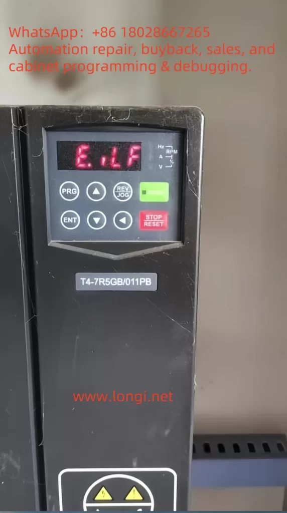
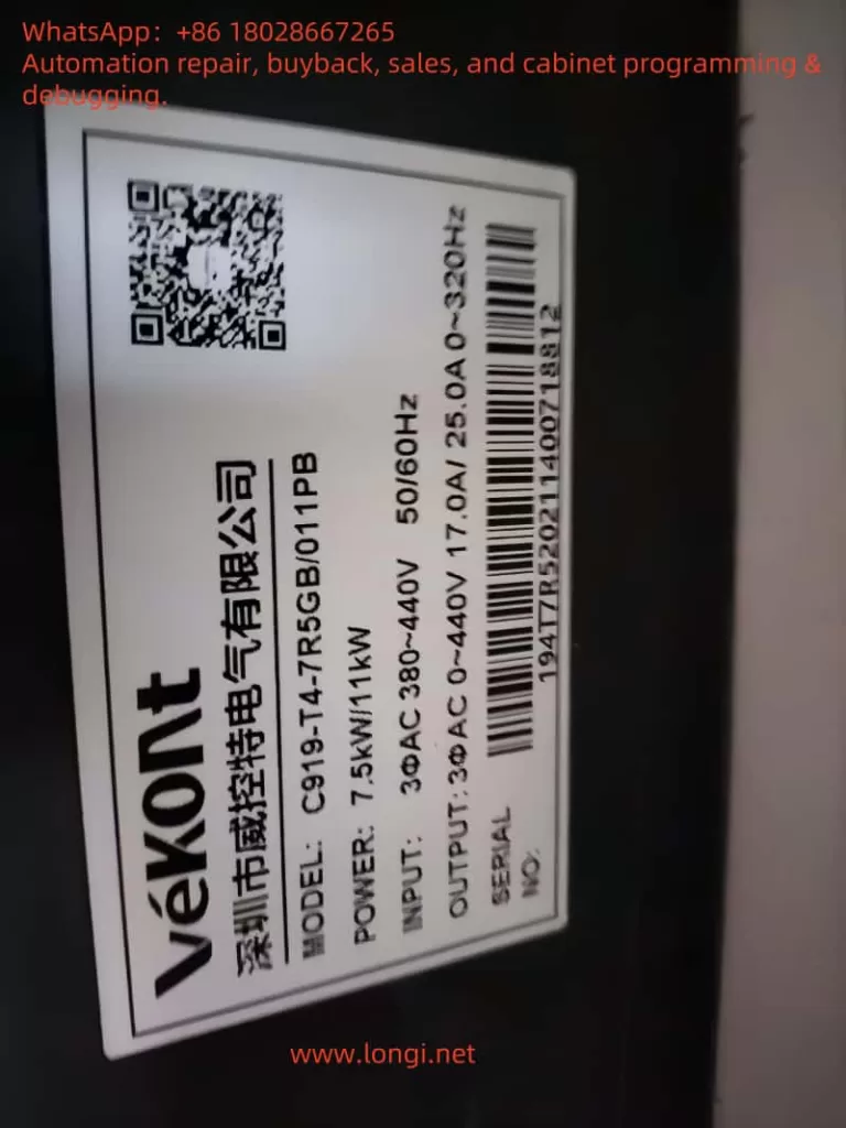
Variable Frequency Drives (VFDs), commonly known as frequency converters, are indispensable components in modern industrial automation systems. By adjusting the frequency and voltage of the input power supply, VFDs enable precise control of motor speed and torque, enhancing operational efficiency and significantly reducing energy consumption. The VEKONT C919 series, renowned for its high reliability and advanced features, has gained widespread adoption across various industrial applications. However, as with any complex electronic device, VFDs are susceptible to faults, with the “E.ILF” fault—indicative of an input phase loss—being a critical issue requiring immediate attention. This article delves into the essence of the E.ILF fault, explores its potential causes, and offers detailed solutions to help users restore normal operation, minimize downtime, and ensure optimal performance of the C919 series VFDs.
The Essence of the E.ILF Fault: Understanding Input Phase Loss
The E.ILF fault in the VEKONT C919 series VFD signals an abnormal condition where at least one phase of the three-phase input power supply is missing or not functioning properly. A three-phase power system consists of three alternating current phases, each separated by a 120-degree phase difference, providing a stable and balanced power input to the VFD. The VFD relies on this balanced supply to rectify the AC input into DC power, which is then inverted into variable-frequency AC power to drive the motor.
When one phase is lost—due to either an external power issue or an internal connection fault—the input power becomes unbalanced, potentially leading to the following complications:
Voltage Imbalance: The remaining two phases may experience overvoltage or undervoltage, placing additional stress on the VFD’s internal components.
Overcurrent Risk: The VFD may attempt to compensate for the missing phase by drawing excessive current through the remaining phases, leading to overheating or component damage.
Abnormal Motor Operation: Due to the incomplete power supply, the driven motor may exhibit insufficient torque, increased vibration, or even fail to start.
The E.ILF fault represents a protective mechanism built into the C919 series VFD, designed to detect input phase loss and halt operation to prevent further damage to the equipment or motor. According to the manual on page 12, this fault can stem from various causes, which will be analyzed in detail below.
Possible Causes of the E.ILF Fault
Based on the fault table in the user manual, the E.ILF fault may arise due to the following four potential issues, each pointing to a distinct problem within the system:
1. Abnormal Three-Phase Input Power
This is the most common cause of an input phase loss fault. Abnormalities in the three-phase input power can result from:
External Power Issues: Such as a phase outage in the power grid, blown fuses, or tripped circuit breakers.
Wiring Problems: Loose, disconnected, or poor-contact connections between the power supply and the VFD.
Upstream Equipment Failure: Faults in transformers or generators supplying power, which may result in the loss of one phase.
2. Drive Board Malfunction
The drive board is a critical component that controls the switching of power semiconductor devices (e.g., IGBTs) to facilitate energy conversion. If the drive board fails—due to aging components, overheating, or damage from electrical surges—it may fail to accurately detect or process one of the input phases, triggering the E.ILF fault.
3. Lightning Protection Board Malfunction
The lightning protection board safeguards the VFD against lightning strikes or transient voltage surges. If this board is damaged (e.g., due to a strike or prolonged wear), it may interfere with the normal detection of the input power or even damage the input circuit, leading to a false or actual phase loss fault.
4. Main Control Unit Anomaly
The main control unit serves as the “brain” of the VFD, coordinating overall operation and executing fault detection. If it malfunctions—due to firmware errors, hardware failures, or disrupted internal communication—it may misjudge the input power status, potentially triggering an E.ILF fault even when the three-phase supply is intact.
Steps to Resolve the E.ILF Fault
Addressing the E.ILF fault requires a systematic troubleshooting approach to identify the root cause and implement appropriate measures. Based on the manual’s recommendations to “check and eliminate issues in peripheral circuits” and “seek technical support,” the following detailed steps are proposed:
Step 1: Inspect and Eliminate Peripheral Circuit Issues
Begin by focusing on the external power supply and related circuits to ensure the three-phase input is functioning correctly. Specific actions include:
1. Verify Power Input
Use a multimeter to measure the voltage across the VFD’s input terminals (L1, L2, L3), ensuring all three phases are balanced (typically within a 5% deviation) and within the C919 series’ rated range (e.g., 380V ±15%, as specified in the manual).
Check the distribution panel for blown fuses or tripped breakers. Replace fuses or reset breakers as needed, and investigate the cause of tripping (e.g., short circuits or overloads).
Inspect the wiring from the power source to the VFD for loose connections, breaks, or burn marks, ensuring all connections are secure and intact.
2. Check Upstream Equipment
If the power is supplied by a transformer or generator, confirm these devices are operating normally and delivering a stable three-phase output.
Use a power quality analyzer (if available) to detect issues like harmonics or voltage sags that might indirectly affect VFD performance.
3. No-Load Testing
Disconnect the VFD from the motor load, power on the VFD alone, and observe whether the E.ILF fault persists. If the fault disappears, the issue may lie with the motor or load—e.g., a shorted winding or ground fault—requiring further motor inspection.
Step 2: Internal Troubleshooting and Technical Support
If the peripheral circuits are functioning normally but the fault persists, the issue may lie within the VFD itself. Proceed with caution and seek professional assistance when necessary. Initial troubleshooting steps include:
1. Inspect the Drive Board and Lightning Protection Board
Power off the VFD, disconnect it from the power supply, and open the enclosure (ensure capacitors are discharged to avoid electrical shock).
Examine the drive board and lightning protection board for visible damage, such as burnt components, swollen capacitors, or cracked solder joints. Replacement may be required if damage is found.
Use a multimeter to test the continuity of key components (e.g., diodes and resistors) on the boards to confirm functionality.
2. Inspect the Main Control Unit
Reset the VFD to factory settings as per the manual to rule out firmware or configuration errors.
If the VFD includes diagnostic software or a display panel, run a self-diagnostic program to check for error codes in the main control unit.
Verify that the firmware version is up to date, and contact the manufacturer for updates if needed.
3. Seek Technical Support
If the above steps fail to resolve the issue, contact VEKONT technical support or a professional technician, providing a detailed fault description and troubleshooting results to expedite resolution.
Depending on the extent of damage, replacement of the drive board, lightning protection board, main control unit, or even the entire VFD may be necessary.
Preventive Measures for E.ILF Faults
To reduce the likelihood of E.ILF faults, consider the following preventive measures:
Regular Maintenance: Schedule periodic equipment inspections to test power stability, tighten connections, and remove dust or debris (e.g., spider webs visible in the provided photo, which could affect electrical contacts).
Install Surge Protection: Add surge protection devices at the power input to ensure the internal lightning protection board functions effectively against lightning strikes or voltage surges.
Monitor Power Quality: Use power quality monitoring equipment to promptly identify and address voltage imbalances or harmonic issues.
Staff Training: Train maintenance personnel in the operation and troubleshooting of the C919 series VFDs to ensure rapid response to issues.
Conclusion
The E.ILF fault, or input phase loss fault, in the VEKONT C919 series VFD is a critical issue requiring timely intervention. Its essence lies in the imbalance of the three-phase input power supply, which can be caused by external power anomalies, drive board malfunctions, lightning protection board failures, or main control unit errors. By following a structured approach—starting with peripheral circuit checks and escalating to internal troubleshooting with technical support—users can effectively resolve the fault. Additionally, adopting preventive measures such as regular maintenance, surge protection, and power quality monitoring can significantly enhance the VFD’s long-term reliability. This article aims to provide practical guidance for C919 series users, ensuring efficient industrial production and equipment safety.
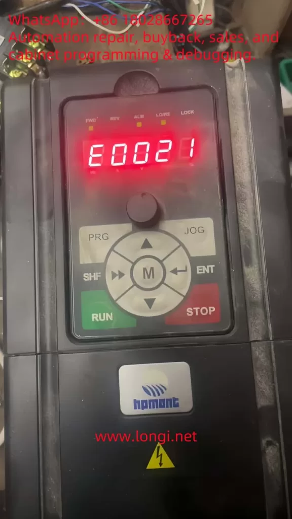
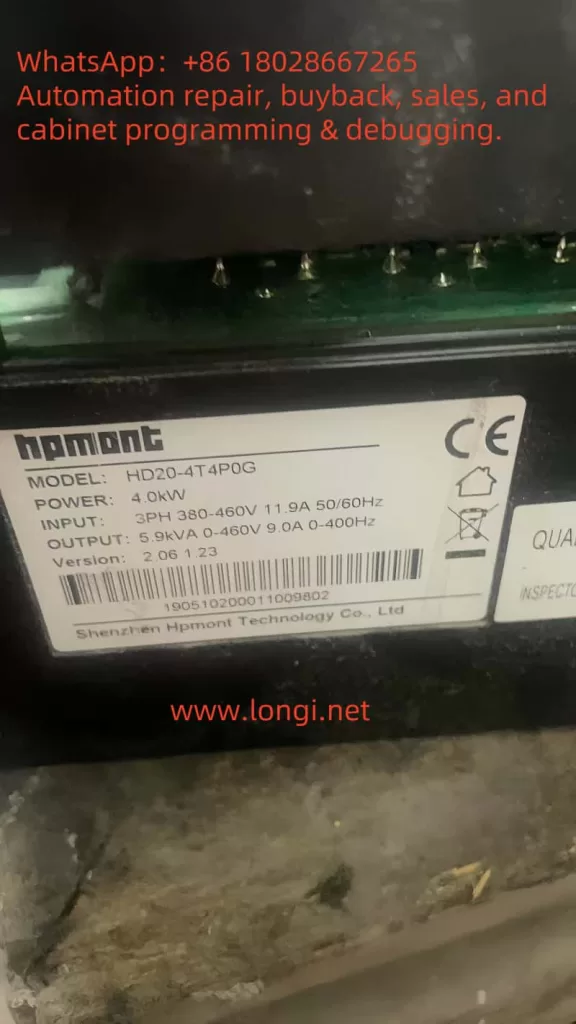
Variable Frequency Drives (VFDs), such as the Hpmont HD20 series, are indispensable in industrial automation, providing precise control over motor speed and torque to enhance efficiency and performance. However, even the most reliable systems can encounter faults that disrupt operations. One such fault, identified by the error code E0021—a “Control Board EEPROM Read/Write Error”—can halt the inverter’s functionality, leading to costly downtime. This article delves into the nature of the E0021 fault, its underlying causes, and offers a detailed, actionable guide to diagnosing and resolving it. Drawing from the HD20 series user manual and fault screenshots, we aim to equip users with the knowledge to restore their inverters efficiently and prevent future occurrences.
What is the E0021 Fault?
The E0021 fault in the Hpmont HD20 series inverter indicates a Control Board EEPROM Read/Write Error. EEPROM, or Electrically Erasable Programmable Read-Only Memory, is a non-volatile memory type integral to the inverter’s control board. It stores essential data, including:
Configuration Parameters: Settings like motor ratings, control modes, and operational limits.
User Settings: Custom adjustments made for specific applications.
Firmware Data: Variables and instructions critical to the inverter’s software operation.
When the inverter displays the E0021 fault, as shown on the control panel with the illuminated “ALM” (alarm) light and the error code in red, it signifies a failure to read from or write to the EEPROM. This disruption can prevent the inverter from loading its operational parameters, resulting in startup failures, erratic behavior, or complete shutdowns. The user manual and fault description (e.g., “控制板EEPROM读写故障” or “Control Board EEPROM Read/Write Fault”) highlight this as a critical issue requiring immediate attention.
The Nature and Essence of the E0021 Fault
At its core, the E0021 fault reflects a breakdown in the inverter’s ability to manage its stored data. The EEPROM’s role is to ensure that the inverter retains its settings across power cycles, making it a cornerstone of reliable operation. A read/write error could stem from:
Data Access Failure: The control board cannot retrieve stored parameters.
Data Modification Failure: New settings or updates cannot be saved.
Data Integrity Issues: Corrupted data renders the EEPROM unreadable or unusable.
This fault’s essence lies in its potential to compromise the inverter’s functionality entirely. Without access to its configuration, the HD20 series inverter cannot control the connected motor effectively, impacting production lines and industrial processes.
Potential Causes of the E0021 Fault
Understanding the root causes of the E0021 fault is crucial for effective troubleshooting. Based on the fault description and general VFD principles, the following factors may contribute:
Power Supply Instability Voltage fluctuations, surges, or sudden power losses can interrupt EEPROM operations. The HD20 series manual (Page 16) specifies a rated voltage (e.g., “额定电压”), and deviations from this range can affect data integrity.
EEPROM Hardware Failure The EEPROM chip may degrade over time due to its finite write cycles (typically 100,000–1,000,000) or suffer damage from electrical stress, heat, or manufacturing defects.
Data Corruption Electrical noise, improper shutdowns, or electromagnetic interference (EMI) in industrial environments can corrupt the EEPROM’s data, making it inaccessible.
Firmware Issues Bugs or corruption in the inverter’s firmware, which manages EEPROM interactions, can lead to read/write errors. An incomplete firmware update could exacerbate this.
Environmental Factors The manual (Page 20, “第三条 机械安装”) advises on installation conditions. Excessive heat, humidity, or dust can degrade the EEPROM and control board.
Control Board Malfunction Damage to other components, such as solder joints or circuits interfacing with the EEPROM, can disrupt communication.
Diagnosing the E0021 Fault
Accurate diagnosis is the first step to resolution. Follow these steps to identify the cause:
Observe Symptoms
Check the control panel (as per the screenshot) for the E0021 code and “ALM” light.
Note if the inverter fails to start, loses settings, or shows additional faults.
Verify Power Supply
Measure input voltage with a multimeter to ensure it aligns with the manual’s specifications (e.g., 380V ±15%).
Look for fluctuations or noise using an oscilloscope if available.
Inspect the Environment
Ensure compliance with installation guidelines (Page 20), checking for proper ventilation, temperature (e.g., 0°C–40°C), and EMI sources.
Power Cycle the Inverter
Turn off the inverter, wait 5 minutes, and restart it to rule out temporary glitches.
Check Firmware and Fault Logs
Access the fault history via the control panel (“PRG” and “ENT” buttons) to identify patterns.
Verify the firmware version against Hpmont’s latest release.
Examine the Control Board
Power down safely and inspect for visible damage (e.g., burnt components, loose connections) around the EEPROM chip (often labeled “24Cxx” or “25Cxx”).
Resolving the E0021 Fault
Once diagnosed, apply these solutions tailored to the cause:
Stabilize Power Supply
Install a surge protector or UPS to mitigate voltage issues.
Ensure proper grounding to reduce EMI.
Reset to Factory Settings
Use the control panel to reset parameters (refer to the manual for exact steps, typically via “PRG” and a reset code).
Reprogram settings post-reset, using backups if available.
Update Firmware
Download the latest firmware from Hpmont’s website and follow update instructions, ensuring an uninterrupted process.
Replace the EEPROM or Control Board
If the EEPROM is faulty, a technician can desolder and replace it with an identical chip, reprogramming it with default or backed-up data.
For broader control board issues, replace the entire board (e.g., compatible with HD20-4T5PSG), then reset and reconfigure.
Address Environmental Issues
Enhance cooling, reduce humidity, or shield the inverter from interference sources.
Preventive Measures
To avoid future E0021 faults:
Maintain Power Quality: Use stabilizers and avoid frequent power interruptions.
Optimize Environment: Adhere to manual guidelines for temperature and humidity.
Regular Maintenance: Inspect and clean the inverter periodically.
Backup Parameters: Save settings regularly if the HD20 supports it.
Conclusion
The E0021 fault—Control Board EEPROM Read/Write Error—in the Hpmont HD20 series inverter is a significant challenge that can disrupt industrial operations. By understanding its nature as a data access failure, identifying causes like power instability or hardware issues, and applying systematic diagnosis and resolution steps, users can restore functionality efficiently. Preventive measures further ensure long-term reliability. For persistent issues, Hpmont’s technical support can provide expert assistance, leveraging the manual’s guidance and replacement parts. This comprehensive approach minimizes downtime and sustains the HD20 series’ performance in demanding applications.
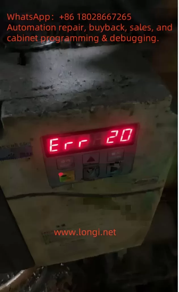
Understanding and Resolving the Err20 Fault (Module Overcurrent) in Baojie Servo AG Series
The Baojie Servo AG Series is a widely utilized industrial servo drive system known for its robust performance and advanced control features. However, like any sophisticated machinery, it is susceptible to operational faults, one of which is the “Err20” fault code displayed on the control panel. This error, accompanied by the indication of “module overcurrent,” signals a critical issue that requires immediate attention to prevent damage to the equipment and ensure uninterrupted production. This article delves into the nature of the Err20 fault, its potential causes, diagnostic procedures, and effective resolution strategies, drawing from the technical insights provided in the AG Series user manual.
What is the Err20 Fault?
The Err20 fault code on the Baojie Servo AG Series control panel indicates a module overcurrent condition. Overcurrent occurs when the electrical current flowing through the servo drive’s power module exceeds its rated capacity. This can lead to overheating, potential damage to the internal components, or even a complete system shutdown to protect the hardware. The user manual highlights that such faults are part of the system’s safety diagnostics, designed to alert operators to issues that could compromise the drive’s integrity or the machinery it controls.
The display of “Err20” alongside a numerical value (e.g., 20) suggests a specific error category within the fault diagnostic framework outlined in Chapter 8 of the manual, “Fault Diagnosis Explanation.” This chapter emphasizes the importance of understanding alarm codes to identify and rectify underlying issues promptly.
Potential Causes of the Err20 Fault
Several factors can trigger the Err20 fault in the Baojie Servo AG Series. Understanding these causes is the first step toward effective troubleshooting:
Overload Conditions: Excessive mechanical load on the servo motor, beyond its specified capacity, can cause the current to spike, triggering the overcurrent protection. This might occur due to jammed machinery or an improperly calibrated load.
Short Circuits: An unintended electrical connection between the drive’s output terminals (e.g., U, V, W) or within the motor wiring can result in a short circuit, leading to a sudden surge in current.
Faulty Wiring or Connections: Loose, damaged, or incorrectly installed wiring can disrupt normal current flow, potentially causing overcurrent conditions. The manual’s Chapter 3, “Installation and Debugging,” stresses the importance of secure and correct wiring practices.
Component Wear or Failure: Over time, components such as the power module, capacitors, or transistors may degrade, especially if maintenance schedules (detailed in Chapter 9, “Maintenance and Care”) are not followed. A failing component can lead to irregular current draw.
Improper Parameter Settings: Incorrect settings in the drive’s internal parameters, such as those adjustable via the operation panel (Chapter 5, “Parameter Setting Explanation”), can misconfigure the current limits, inadvertently allowing overcurrent situations.
Environmental Factors: Operating the drive in harsh conditions—high temperatures, dust, or humidity—can affect its performance. The manual recommends regular cleaning (e.g., Section 9.4 for 7.5-11kW drive cleaning methods) to mitigate such risks.
Diagnostic Procedures
To resolve the Err20 fault, a systematic diagnostic approach is essential. The following steps, informed by the manual’s guidelines, should be undertaken:
Initial Safety Check: Ensure the power supply is disconnected, as advised in Section 9.2 for insulation testing, to avoid electrical hazards during inspection.
Visual Inspection: Examine the control panel, wiring, and motor for visible signs of damage, loose connections, or burn marks. Refer to Chapter 3.7 for the control terminal function table to verify wiring integrity.
Review Operating Conditions: Check the mechanical load and operating environment. Compare the current load against the motor’s specifications listed in Chapter 4.7, “Servo Motor Parameter Table.”
Parameter Verification: Access the operation panel (Section 5.1) to review and reset parameters under the “PA” or “PB” menus, ensuring they align with the application’s requirements.
Testing with Diagnostic Tools: Use a multimeter to test for short circuits or abnormal current draw, following the insulation test procedures in Section 9.2. A resistance value of 5 MΩ or higher indicates normal insulation.
Monitor System Logs: If the drive supports logging (as hinted in Chapter 6, “Computer Screen Parameter Monitoring”), review historical data to identify patterns leading to the fault.
Resolution Strategies
Once the cause is identified, the following corrective actions can be implemented:
Addressing Overload: Reduce the mechanical load by inspecting and repairing any jams or obstructions. Recalibrate the system to match the load to the motor’s rated capacity, as per the selection guidelines in Chapter 4.9.
Fixing Short Circuits: Trace and repair any shorted wires or terminals. Replace damaged cables or connectors, ensuring compliance with the wiring instructions in Chapter 3.11.
Repairing Connections: Tighten loose connections and replace any frayed or corroded wires. Refer to the user manual’s wiring diagrams for accuracy.
Replacing Faulty Components: If a component failure is suspected, replace it with a compatible part. The manual’s Section 9.3 provides a replacement schedule (e.g., fans every 3 years, capacitors every 5 years), which should guide the decision.
Adjusting Parameters: Correct any misconfigured parameters using the panel’s menu system. Ensure changes are made with the power off, as warned in Section 5.5.
Environmental Control: Clean the drive using the methods in Section 9.4 (e.g., blowing dust with air) and relocate it if environmental conditions are unfavorable. Install cooling systems if necessary.
Preventive Measures
To prevent recurrence of the Err20 fault, adopt the following practices:
Regular Maintenance: Follow the daily checks and periodic maintenance outlined in Chapter 9.1, including insulation tests and component replacements.
Training Operators: Ensure personnel are trained in the parameter settings and fault diagnosis procedures detailed in Chapters 5 and 8.
Environmental Monitoring: Maintain the operating environment within the recommended temperature and humidity ranges, as noted throughout the manual.
Load Management: Regularly assess and adjust the mechanical load to prevent exceeding the drive’s capacity.
Conclusion
The Err20 fault (module overcurrent) in the Baojie Servo AG Series is a critical alert that demands a thorough understanding of its causes and a structured approach to resolution. By leveraging the detailed guidance in the user manual—spanning installation, parameter settings, fault diagnosis, and maintenance—operators can effectively diagnose and rectify this issue. Implementing preventive measures ensures the longevity and reliability of the servo drive system, minimizing downtime and maintaining productivity. For complex cases or persistent faults, consulting the manufacturer’s technical support, as recommended in the manual’s preface, can provide additional expertise. With proactive management, the AG Series can continue to deliver optimal performance in industrial applications.